Search results
Query: ground wave
Links: 103 | Categories: 1
-
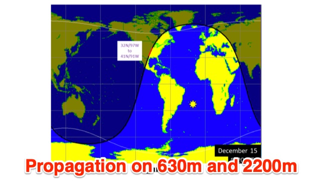 This is a theoretical look at propagation on 630-Meters and 2200-Meters using ray tracing software. It expands on the brief discussion in the ARRL Handbooks. The Earth's magnetic field affects 630-Meter and 2200-Meter band propagation. Lower ionization reduces absorption, aiding low-frequency propagation. Differences exist between bands, limited daytime sky-wave propagation. Sunrise/sunset show promise, yet mechanisms are unclear. Ducting possible at night in specific conditions. Negative ions enhance propagation. Inefficient antennas and high man-made noise are anticipated. Groundwave propagation is significant on 2200-Meters.
 -
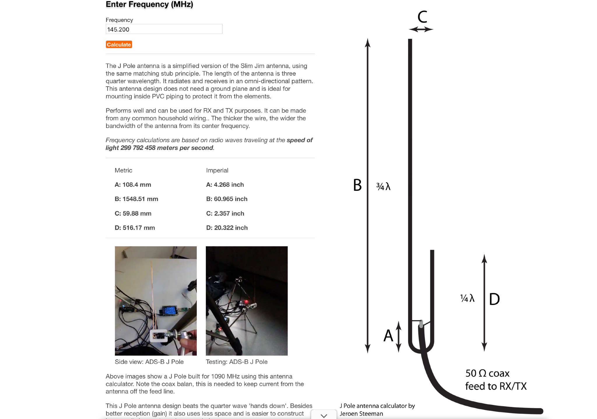 This web page offers an online antenna designer tool for hams to calculate the dimensions needed to construct a J Pole antenna for any desired frequency. The J Pole antenna is a simplified version of the Slim Jim antenna, radiating and receiving signals in an omni-directional pattern. It does not require a ground plane, making it suitable for indoor mounting. With the ability to be made from common household wiring, this antenna performs well for both receiving and transmitting purposes. The calculator is based on radio waves traveling at the speed of light and provides metrics in both imperial and metric units.
 -
 Constructing a **J-Pole antenna** from 450 Ohm ladder line for 2-meter (144 MHz) and 70-centimeter (440 MHz) operation involves specific calculations and assembly steps. The design, based on an earlier KD6GLF concept using 300 Ohm twinlead, features a ¾ wavelength radiator and a ¼ wavelength matching stub, functioning as an end-fed half-wave antenna without requiring ground radials. It offers a gain of 2.4 dB over isotropic. The resource provides the formulas for determining the lengths of the ¾ wave radiator and ¼ wave stub, incorporating a velocity factor of 91% for 450 Ohm ladder line. For 146 MHz, the radiator measures 55 3/16 inches and the stub 18 3/8 inches. Construction details include cutting a 57¾-inch piece of ladder line, stripping 4 inches from one end, and attaching a 24-inch section of RG58 or RG8X coax with a 3-5 turn RF choke. SWR adjustment is achieved by sliding a shorting bar or by incrementally trimming the elements at a 1:3 ratio (stub to radiator). The goal is a 1:1.1 SWR at 146 MHz, which typically yields 1:1.2 at 446 MHz. The article also discusses power handling, noting that while 10-15 watts is fine, 50 watts may increase SWR to 1:2.1, and advises keeping the antenna away from other objects to prevent coupling and SWR degradation.