Search results
Query: nec model
Links: 112 | Categories: 0
-
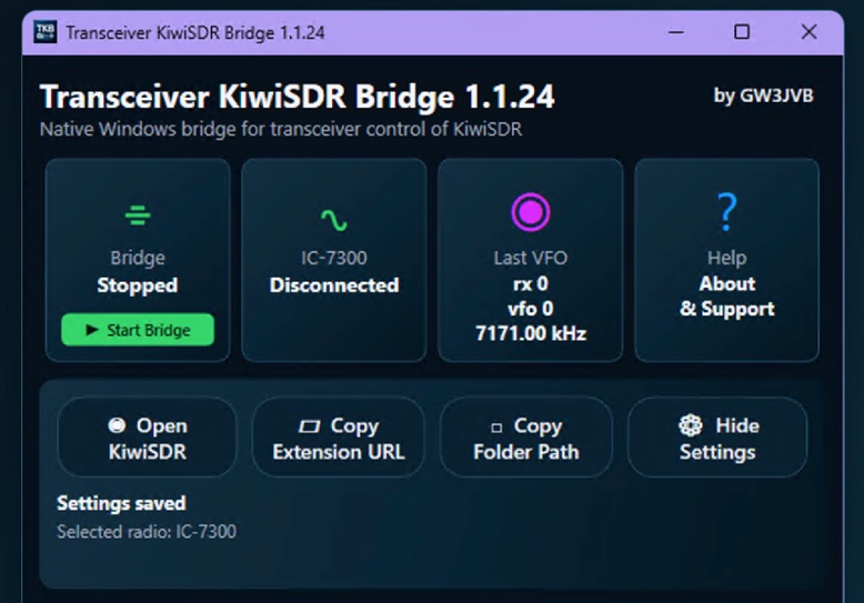 Demonstrates a practical solution for remote reception, the Transceiver-KiwiSDR Bridge, a free Windows utility by GW3JVB. This software links a local amateur radio transceiver to a remote **KiwiSDR** receiver, allowing the KiwiSDR to automatically track the transceiver's VFO frequency and mode. This capability proves invaluable for mitigating local noise, enhancing reception, or simply leveraging the superior receive capabilities of a remote station located globally. The bridge supports a diverse range of transceivers through COM port/CAT connections or **TCI** over a network. Specific compatibility extends to popular models like the Icom IC-7300, systems utilizing the TCI Protocol (such as Thetis, Expert Electronics, Apache Labs ANAN, and Hermes Lite 2), and many radios supported by Hamlib. Experimental Yaesu CAT options are also included, broadening its utility for various shack configurations. Key features encompass automatic mode changes, updates to RX filter bandwidth, and even IC-7300 PBT/filter adjustments. The application integrates a browser extension for Chrome, Brave, and Microsoft Edge, and offers an optional KiwiSDR audio mute during local transmission, ensuring a seamless operating experience. The compact view keeps the interface unobtrusive, with full settings readily accessible.
 -
 Designing a collapsible 6-meter beam antenna involves careful consideration of element geometry and feedline matching, as demonstrated by VE3SMA's project. The construction draws inspiration from foldable dipole concepts and established wire beam designs like the Penn. State 40m beam and the DJ4SA Spiderbeam. Utilizing **4NEC2 modeling**, the author optimized element lengths for gain and bandwidth, observing the impact of end loops on resonant frequency and the need for compensation. Feeding the approximately 25-ohm balanced antenna with 50-ohm unbalanced cable required a specialized network. This setup incorporates a choke **balun** and a matching section built from two series quarter-wave transformers using readily available 75-ohm cable. On-the-air results validate the design, including a successful 1st double hop Es QSO with 10 Watts and satisfactory performance in the CW WW VHF Contest from FN05, where 41 grids were worked with 100 Watts, showing improved performance over a simple dipole.
 -
 This article explores the powerful features of AutoEZ as an Excel application working with EZNEC antenna modeling software. The article demonstrates how variables, equations, and formulas enable versatile antenna design and automatic optimization. Through practical examples including dipoles, inverted vees, delta loops, and monopoles, the author shows techniques for achieving resonance, implementing transmission line resonators for broadbanding, and optimizing antennas across frequency ranges. The step-by-step demonstrations cover unit conversion, coordinate calculations, segmentation considerations, and SWR optimization. This practical guide illustrates how AutoEZ extends EZNEC's capabilities, making complex antenna modeling more efficient and accessible.
 -
 Presents the design and construction of a folding 5-element Yagi antenna specifically engineered for 144 MHz portable operation, particularly for VHF contest Rover categories. It details element dimensions, boom construction using ¾-inch pine, and a folding mechanism that reduces the 52-inch boom to 26 inches for transport. The document provides a table with precise element distances and lengths, including a 2.4 mm length correction for solid parasitic elements, and specifies the use of 3/16-inch solid aluminum for parasitic elements and brass tubing for the driven element. It also covers the bent dipole driven element design for impedance matching, balun implementation with Type 31 ferrite beads for common mode current suppression, and weatherproofing for the feed point. The resource includes predicted performance data from 4NEC2 modeling, showing SWR and return loss characteristics, as well as gain and front-to-back ratios at various frequencies across the 2-meter band. It reports a measured SWR of 1.2:1 at 144.2 MHz and 1.5:1 at 147 MHz, corrected for 25 feet of RG-8/M coaxial cable loss. The design offers approximately 1.5 dB more gain than a previous 4-element design, maintaining a decent SWR up to 147 MHz, and was successfully deployed in a winning June 2016 ARRL VHF Contest Rover entry.
 -
 This project outlines a simple, cost-effective 40m band HF dipole antenna design, ideal for beginners. Constructed with insulated copper wire and a 1:1 balun, it offers a 50-ohm impedance, suitable for both 40m and 15m bands due to the harmonic relationship. Calculations account for a K factor, ensuring optimal length and performance. Antenna modeling with 4NEC2 confirms practical access to both bands, though real-world results may vary. Lightweight materials and straightforward assembly make it an accessible and versatile amateur radio solution.
 -
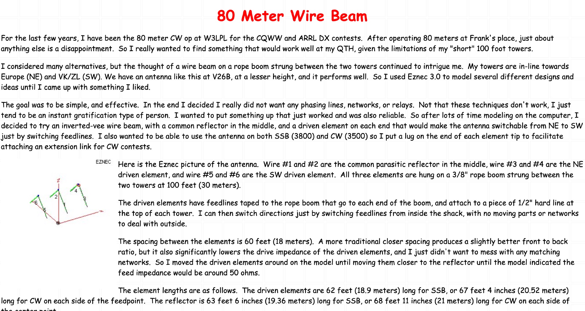 This paper presents an 80 meter wire 3-element beam antenna in an inverted-V configuration, designed for limited-height towers. Using EZNEC modeling, the antenna features a central parasitic reflector and two switchable driven elements at each end, enabling NE/SW coverage without moving parts or networks. Element lengths are optimized for SSB (3.8 MHz) and CW (3.5 MHz) operation, with a 50 Ω feed and rope-supported boom. The design delivers high gain, effective takeoff angles, and excellent reception, confirmed in real-world DX contest operation. Its simplicity, reliability, and ease of construction make it ideal for operators seeking performance without complex matching systems.
 -
 The Zeppelin antenna, a J-type design, is presented as a two-band HF dipole, offering independent operation on harmonically related frequencies. This resource details its electrical configuration, comprising a half-wave radiator end-fed by a quarter-wave matching section, and explores its historical evolution from early Zeppelin airship applications to modern amateur radio use. The article specifically examines how a Zepp antenna tuned to 28.4 MHz (10 meters) exhibits a harmonic relationship with 15.4 MHz (20 meters), noting a frequency ratio of approximately 1.84:1, which deviates from a perfect 2:1 due to factors like elevation, wire separation, velocity factor, and end-effect. Antenna modeling results, including SWR sweeps at 28.4 MHz (1.1 SWR) and 15.4 MHz (1.6 SWR), are provided through Graph 1 and Graph 2, illustrating the antenna's performance across these bands. Current distribution patterns for both the 28.4 MHz (second harmonic) and 15.4 MHz (first harmonic) operations are visually represented in Figure 2 and Figure 3, respectively. The author also includes a 4NEC2 model's "Symbol Conversion file" definitions and calculated #14 wire dimensions for achieving resonance at 28.4 MHz, with the antenna positioned at a height of 33 feet. The discussion further highlights the antenna's versatility, suggesting its potential as a single-band, center-fed, 15.4 MHz half-wave folded end dipole when fed at a specific low current point. This analysis provides practical insights into constructing and optimizing a multi-band Zepp antenna for HF operations, emphasizing its unique harmonic characteristics and physical compactness.
 -
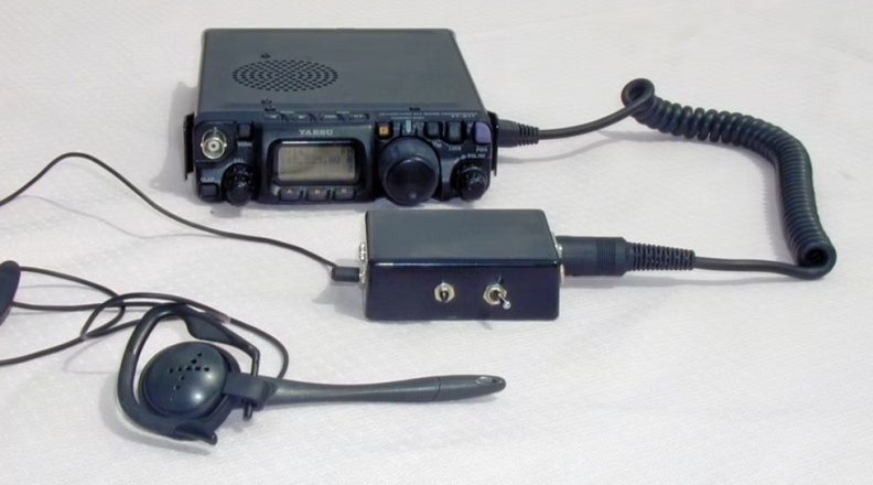 This online project documentation details the construction of a hands-free microphone interface unit designed for _mobile_ amateur radio operation. The curriculum covers the integration of electret microphone elements with amateur radio transceivers, specifically addressing **VHF** band communication. It outlines the circuitry for a switch box that provides an interface between various radio models and microphone types. The guide specifies the inclusion of a **1750 Hz** tone-burst generator for accessing amateur radio repeaters, an operational protocol for many VHF systems. Design considerations include the reduction of ambient vehicle noise through an adjustable audio input level control. The project provides schematics and wiring diagrams for connecting the interface unit to specific amateur radio transceivers, including the Yaesu FT-817. It addresses the selection and adaptation of readily available electret microphone and earpiece assemblies, initially sourced from mobile phone accessories, and later from dedicated headset units. The design incorporates a control mechanism for radio functions, enabling hands-free operation during _mobile_ excursions. Circuit details cover power supply considerations for the electret microphone and signal routing for both transmit audio and received audio monitoring. The documentation specifies component selection for the switch box, ensuring compatibility with common amateur radio microphone input impedances and output levels. This includes considerations for PTT line switching and audio path isolation. DXZone Focus: Online Project Documentation | Hands-Free Mobile Microphone Interface | Electret Microphone Integration | 1750 Hz Tone-Burst Generation
 -
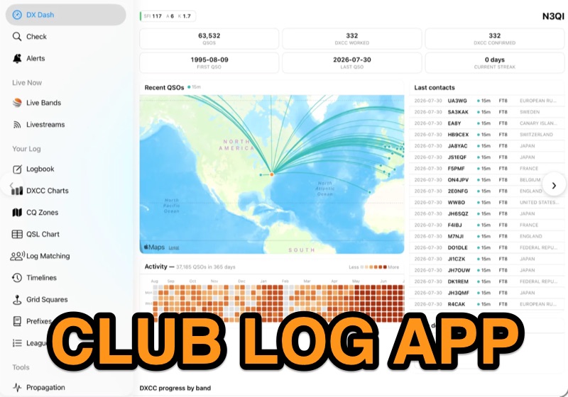 Examines the Club Log mobile application, detailing its functionality for **DXCC** and **DXCC Challenge** enthusiasts on HF and 6 meters, across SSB, CW, and data modes. The application provides real-time push notifications by monitoring live QSO activity across the entire Club Log database, cross-referencing it with the user's specific needs for new entities or band-mode slots. Users can also pin specific callsigns to receive immediate alerts when those stations become active on the air. The resource highlights the app's ability to replicate most clublog.org website features natively on mobile devices, including international translations for 22 languages. It also integrates an offline logbook that synchronizes with the online platform when connectivity is available. The app requires a Club Log account and supports real-time logging from external software or offers an integrated logbook tool for direct QSO submission. Further, the page explains the subscription model necessary to sustain the app's development and operational costs, particularly for the innovative real-time alerting system. It clarifies how subscriptions are managed through App Store or Google Play, with pricing varying by region.
 -
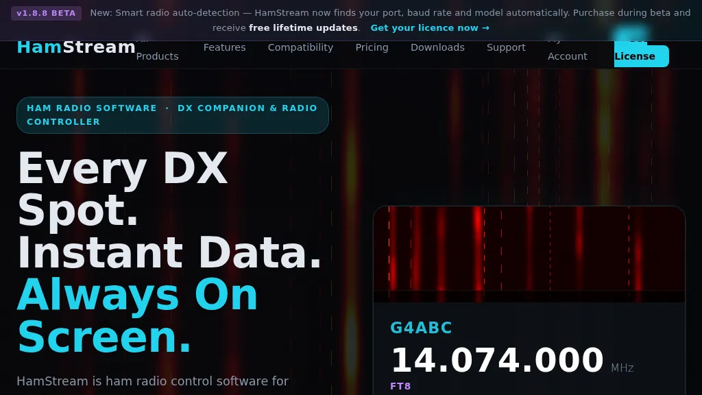 HamStream, a versatile ham radio control software, integrates real-time DX cluster data directly into the operator's workflow, eliminating the need for constant alt-tabbing. As an Extra Class operator, I appreciate how it instantly displays callsign, country, distance, bearing, and QRZ profile data for spotted stations, mirroring the efficiency of a well-organized shack. The software acts as a comprehensive radio controller, reading frequency, mode, and S-meter in real time from connected rigs, supporting CAT via serial, CI-V, _HAMLIB_, and direct connections to _FlexRadio SmartSDR_ and Apache Labs ANAN (via Thetis). Key features include instant QRZ lookups, distance and bearing calculations with a live great-circle minimap, and favorite alerts for specific callsigns. The one-click logging functionality is particularly useful, populating callsign, frequency, and mode into _N1MM+_, Log4OM, DXKeeper, Logger32, StationMaster Pro, and Ham Radio Deluxe via UDP, streamlining contest and casual logging alike. Its smart radio auto-detection for port, baud rate, and model simplifies setup, a welcome relief from manual configuration. Beyond core operating, HamStream also displays 'Also on this frequency' information and can tune the radio to spotted frequencies, enhancing situational awareness. For those who stream their operations, it offers an OBS overlay with live viewer counts and chat integration, making it a compelling tool for modern amateur radio engagement.
 -
 Demonstrates the design and modeling of a **160m** vertical antenna, dubbed the "WindoVert," specifically for urban amateur radio operators with limited space. The resource covers the theoretical underpinnings of antenna height and radiation patterns, using EZNEC software to analyze current distribution and 3D radiation patterns for various configurations, including a Marconi-style "T" antenna. It details the integration of existing antenna components, such as a Carolina Windom balun and line isolator, into the new vertical setup, and the practical measurement of feedpoint impedance using an antenna analyzer. The article further explores the challenges of achieving low-angle radiation on Top Band, emphasizing the critical role of radial systems and mitigating ground loss. Author VE1ZAC presents EZNEC models illustrating the impact of lumped components and discusses the practical considerations of resonant frequency adjustment and impedance matching for **QRP** operation. The text details the calculation of required loading coil inductance and capacitance, and shares field results, including successful DX contacts on 160m and unexpected excellent performance on 30m.
 -
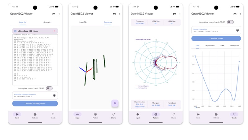 The Open NEC2 Viewer for Android provides a mobile platform for **NEC2** antenna modeling, enabling users to visualize and analyze antenna designs directly on their devices. It integrates the robust NEC2 computational library, leveraging the Method of Moments for full-wave electromagnetic analysis, and utilizes the Google Filament renderer for interactive 3D visualization of antenna structures, segmentation, and wireframes. The application facilitates the calculation of geometric parameters and antenna characteristics across specified frequency ranges. Key functionalities include parametric analysis, offering real-time computation of **radiation patterns** (RP), antenna gain, Voltage Standing Wave Ratio (VSWR), and input impedance. Users can configure flexible calculation settings to control scan step, frequency range, and various control cards, allowing for detailed electromagnetic analysis tailored to specific design requirements. Designed for radio engineers, antenna developers, radio amateurs, and students, the app is distributed as open-source software under the GNU General Public License v3.0. It provides a portable and accessible tool for electromagnetic modeling, making advanced antenna analysis capabilities available on Android devices.