Search results
Query: transmit ant
Links: 166 | Categories: 4
-
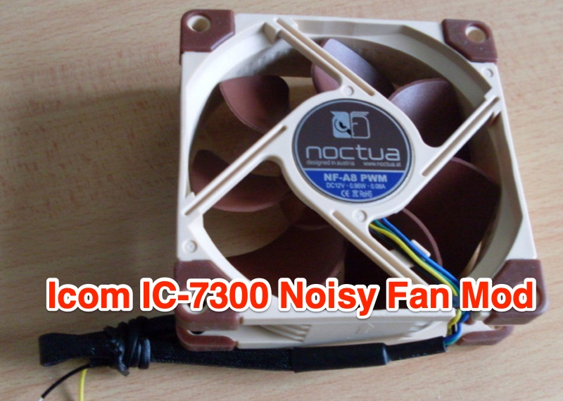 The Icom IC-7300 transceiver's stock cooling fan, a 12VDC unit typically run at 6VDC with a 10VDC transmit kick, is often perceived as noisy. This modification replaces the original fan with a **Noctua NF-A8 PWM** fan, which is described as "silent" even during the initial 10V transmit kick. The resource provides specific wiring details, noting black for negative and yellow for positive connections, and suggests using readily available 2-pin fan plugs for a clean installation. This fan replacement significantly reduces operational noise, improving the user experience of the IC-7300. The Noctua NF-A8 PWM fan is available for under £20 in the UK, making it an accessible upgrade. The modification is presented as a straightforward process, enhancing the rig's acoustic profile without compromising cooling efficiency, based on the experience of Bjorn Eklund, **SM7IUN**.
 -
 Operating amateur radio satellites presents unique challenges, particularly concerning antenna design and signal propagation. Juan Antonio Fernández Montaña, EA4CYQ, recounts his three-year journey into satellite communication, starting with initial guidance from EB4DKA. His early experiments involved a portable 1/4 wave VHF antenna with four 1/4 wave ground planes, designed for hand-held use to adjust polarity. This setup, paired with an FT-3000M transceiver, allowed full-duplex operation on **VHF** transmit and **UHF** receive, proving effective for early contacts on satellites like AO27, UO14, and SO35. EA4CYQ's experience highlights the critical role of coaxial cable loss and antenna polarization. After encountering significant signal degradation with longer RG213 runs, he experimented with a 1/2 inch commercial cable, noting improved reception but persistent fading due to varying satellite polarities. This led to the construction of an **Eggbeater II** antenna, an omnidirectional UHF design offering horizontal polarization at the horizon and circular right polarization at higher elevation angles. Subsequent modifications resulted in the directional **TPM2** antenna, which provided sufficient gain for LEO satellites with a wide 30-degree lobe, enabling consistent contacts from his home station. The article concludes with practical insights on the performance of the Eggbeater II for both UHF and VHF, and the TPM2 for UHF, emphasizing their utility for portable and fixed operations. EA4CYQ's journey underscores the iterative process of antenna development and the importance of adapting designs to overcome real-world propagation challenges in satellite communications.
 -
 Details the construction and performance of a phase-controlled receiving array, specifically a **MicroSWA** variant, optimized for QRP low band fox hunting on 40M and 80M. The resource documents the author's iterative design process, addressing significant regional noise challenges encountered during 0100-0230 UTC fox hunt periods. Initial experiments involved a director wire on a 40M vertical, yielding limited improvement, prompting a shift towards advanced null-steering techniques. The project leverages concepts from Victor Misek’s "The Beverage Antenna Handbook" and Dallas Lankford’s extensive work on phased receiving antennas for urban lots. A key modification involved integrating a new passive phase control box and a push-pull **Norton common base preamp** using 2N5109 transistors, designed for high third-order intercept performance to maintain weak signal integrity amidst strong adjacent signals. The system incorporates Faraday-shielded transformers with RG174 primaries on -75 ferrite cores, housed in ABS plastic pipe. Performance tests confirmed the MicroSWA's ability to produce deep, steerable nulls, achieving approximately 30 dB noise reduction on 160M, 80M, and 40M. This enabled detection of QRP signals undetectable on conventional transmit antennas. The final unit includes front panel controls, a 10-11 dB preamp, and a robust power conditioner, demonstrating effective noise mitigation for challenging low band QRP operations.
 -
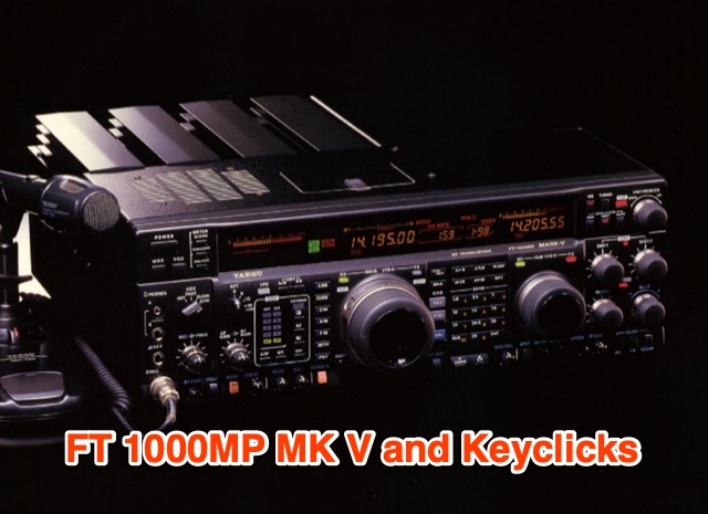 YaesuFT1000MK V stands out with improved close-spaced SSB transmit performance, reversing a trend seen in other modern radios. Featuring a class-A mode, it offers clean HV finals when kept out of ALC. However, two significant flaws persist: the noise blanker causes receiver IM distortion, and the transmitter lacks wave-shaping on CW, resulting in pronounced keyclicks. Preliminary tests reveal strong keyclicks +1kHz and -1kHz, prompting a combined modification to address both issues.
 -
 The Olivia digital mode, a **Multi-Frequency Shift Keying (MFSK)** radioteletype protocol, is specifically engineered for robust communication under difficult propagation conditions on shortwave radio bands from 3 MHz to 30 MHz. Developed by Pawel Jalocha in 2003, Olivia signals can be decoded even when the noise amplitude exceeds the digital signal by over ten times, making it highly effective for transmitting ASCII characters across noisy channels with significant fading and propagation phasing. Early on-the-air tests by Fred OH/DK4ZC and Les VK2DSG on the Europe-Australia 20-meter path demonstrated intercontinental contacts with as little as one-watt RF power under favorable conditions. Common Olivia modes are designated as X/Y, where X represents the number of tones and Y is the bandwidth in Hertz, with examples including 8/250, 16/500, and 32/1000. The resource clarifies that Olivia, unlike some other digital modes, produces a constant envelope, allowing RF power amplifiers to achieve greater conversion efficiencies and making it less prone to non-linearity. Operators are advised that **Automatic Level Control (ALC)** can be set higher than no meter movement for MFSK modulation, as long as it's not driven past its high limit, contrary to common misinformation about other digital modes. The Olivia community encourages voluntary channelization on suggested calling frequencies, such as 14.0725 MHz for 8/250, to facilitate initial contacts, especially for signals below the noise floor. The Olivia Digital DXers Club provides links to Groups.io, Facebook, and Discord for community engagement and offers details on QSO parties.
 -
 Twenty 1-watt carbon film resistors are configured in parallel to construct a 50-ohm **dummy load** for amateur radio applications. The design incorporates a heatsink for thermal dissipation and an **SO-239 connector** for RF input, making it suitable for QRP operations. This budget-friendly project details component selection, soldering techniques, and mounting procedures, achieving a continuous power rating of 10 watts and intermittent handling of up to 100 watts across HF and VHF frequency ranges. The resource provides a step-by-step guide for assembly. This construction offers an economical solution for essential shack tasks such as antenna tuning, transmitter testing, and SWR meter calibration without radiating an RF signal. The utilization of readily available components significantly reduces the overall build cost compared to commercial alternatives, providing radio amateurs with a functional and reliable test accessory. While specific VSWR measurements are not provided, the design prioritizes practical utility for low-power transceiver diagnostics and general RF experimentation.
 -
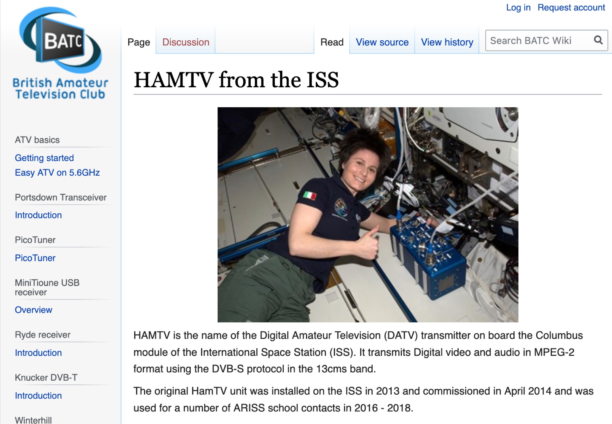 Learn about the HAMTV Digital Amateur Television (DATV) transmitter on the International Space Station (ISS), transmitting video and audio in MPEG-2 format using the DVB-S protocol. Discover its history, installations, failures, and repairs, as well as the current status and live video feed. Explore the technical details and challenges of the HAMTV transmitter, including power output, polarization, and antenna location. Find recordings of previous transmissions and understand the potential signal reflections caused by various ISS components. Stay updated on the latest developments and activities related to HAMTV from the ISS.
 -
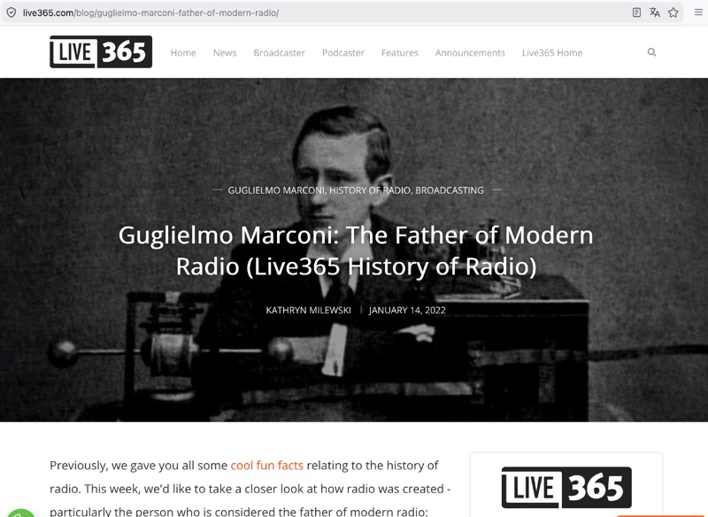 Tracing the foundational work of Guglielmo Marconi, this article details his early laboratory experiments in 1895, where he successfully transmitted wireless signals over 1.5 miles. It highlights his 1896 patent for a wireless telegraphy system in England and subsequent demonstrations, including signal transmissions up to 6.4 km (4 miles) on Salisbury Plain and nearly 14.5 km (9 miles) across the Bristol Channel. Marconi's work built upon the mathematical theories of _James Clerk Maxwell_ and the experimental results of _Heinrich Hertz_, proving the practical feasibility of radio communication. The resource further chronicles the formation of The Wireless Telegraph & Signal Company Limited in 1897 and Marconi's relentless efforts to popularize radiotelegraphy. A significant milestone was the 1901 transatlantic reception of the Morse code letter "S" from Poldhu, Cornwall, at St. John's, Newfoundland, using a kite-supported wire antenna, defying contemporary mathematical predictions about Earth's curvature limiting range. This achievement underscored the global potential of radio. The article also touches upon Marconi's later discoveries, such as the "daytime effect" concerning atmospheric reflection of radio waves, and his 1902 patent for a magnetic detector, which became a standard wireless receiver. His contributions earned him a Nobel Prize in 1909.
 -
 MeshCom 4.0 facilitates off-grid text messaging and data exchange via _LoRa_ radio modules, operating on low-power, low-cost hardware to establish networked communication capabilities. The system transmits messages, GPS positions, sensor values, and telecontrol data over significant distances with minimal power consumption. MeshCom modules can autonomously form a mesh network or integrate into a broader message network through MeshCom gateways, which ideally connect via _HAMNET_ to link disparate radio networks. Recent updates include MCMAP features, support for Lilygo T-Connect-Pro, and new firmware for T-ECHO, enhancing the system's versatility. The project provides basic specifications, detailed protocol information, and installation instructions for MeshCom 4.0, including guides for RAK WisBlock and HELTEC V3 hardware. Firmware and companion Android/iPhone applications are available for download, supporting a range of **10-20 km** line-of-sight communication.
 -
 SAT filters ensure effective full-duplex satellite QSOs by mitigating interference between 145 MHz uplink and 435 MHz downlink signals. Custom coaxial and SMD-based filters address transmitter harmonic interference and improve receiver isolation, achieving over 70 dB suppression in the undesired band. Designed for simplicity, these filters maintain optimal VSWR and are housed in shielded brass enclosures. Practical implementations with Yagi antennas demonstrate compatibility with SDR systems, enabling seamless communication even in challenging satellite conditions, such as low-elevation passes and DX pile-ups.
 -
 Early 20th-century transatlantic wireless communication efforts involved distinct technical approaches by Reginald Fessenden and Guglielmo Marconi. Marconi's systems, operational until approximately 1912, primarily utilized _spark technology_ for wireless telegraphy, facilitating Morse code communication between ships and across oceans. His Poldhu station in December 1901 radiated signals in the MF band around 850 kHz, later evolving to 272 kHz in October 1902, and eventually 45 kHz by late 1907 with increasingly larger antenna structures like the pyramidal monopole and capacitive top-loaded arrays. Fessenden, conversely, focused on _continuous wave transmission_ for wireless telephony, recognizing its necessity for speech. His transatlantic experiments in 1906 employed synchronous rotary-spark-gap transmitters and 420-foot umbrella top-loaded antennas at Brant Rock, MA, and Machrihanish, Scotland, tuned to approximately 80 kHz. Fessenden later utilized the _Alexanderson HF alternator_ at 75 kHz by late 1906 for pure CW transmission, integrating a carbon microphone for amplitude modulation. Receiver technology also differed, with Marconi initially relying on untuned coherer-type detectors, later developing the magnetic detector in 1902, while Fessenden's CW approach necessitated more advanced detection methods.
 -
 Optimizing on-air audio for SSB, DXing, and contesting operations is addressed through a range of specialized audio processing equipment. The offerings include multi-band equalizers, specifically 5-band, 8-band, 10-band, and 12-band units, some integrated with features such as compressors, echo effects, noise gates, and phase rotation capabilities. These devices are engineered to interface with common amateur radio transceivers, with explicit compatibility noted for models like the Yaesu FT-DX10, FT-DX101D, FT-1000MP, FT-DX5000, Collins HF-380, and Flex 6300, alongside analog S/P meters for Icom rigs. The product line focuses on enhancing microphone audio characteristics, supporting XLR dynamic microphones for improved signal clarity and presence. The manufacturer, DB6QW Electronics, emphasizes direct support and a 100% manufacturer's warranty, reflecting confidence in product quality and operational reliability. This resource details specific audio processing tools designed to refine the transmitted audio signal, providing operators with granular control over their voice characteristics for competitive and casual amateur radio communications.
 -
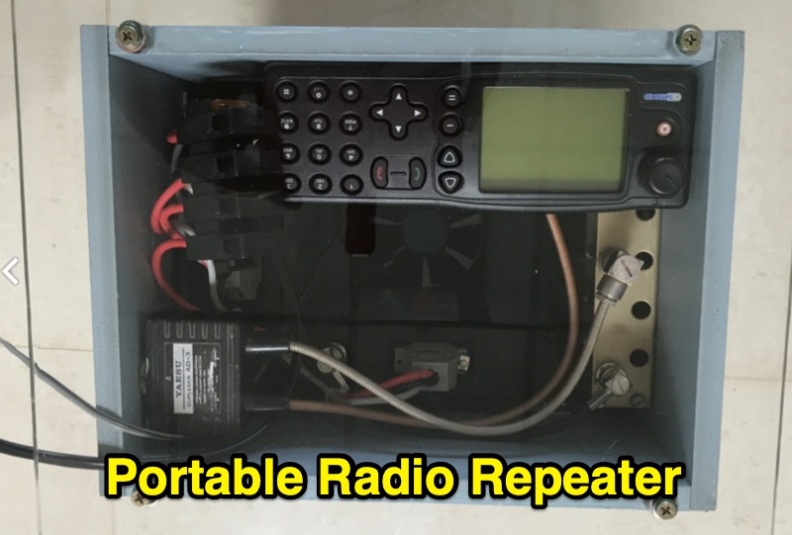 Demonstrates the construction of a portable 2-meter repeater system utilizing a **Yaesu DR-1X** transceiver, configured for both analog FM and C4FM digital voice operation. The design emphasizes portability, robustness, and effective thermal management, incorporating a "wind tunnel" airflow system with a fan to maintain transmit module temperatures at 38 degrees Celsius during continuous operation. The system integrates a diplexer, control head, and is housed in a compact, lightweight case weighing under 8kg, designed for single-person deployment. Covers practical considerations for field deployment, including power sources, antenna types, and the overall system architecture for public service events and emergency preparedness. The resource details the modular "wrap around" construction, showing how components like thermal switches for fan control and Anderson Powerpole connectors are integrated. It highlights the system's ability to provide reliable communications support for club activities and emergency communications.
 -
 Learn about Amateur Television (ATV) on the 23 cm band (1240-1300 MHz) in this article from the September and October 2000 issue of Mégahertz magazine. Discover how ATV adds a new dimension to QSOs by allowing hams to visit stations, transmit real reports on antenna installations, follow signal paths on camera, and have simultaneous sound transmission. Explore the world of ATV experimentation, comparison, and innovation, made easier by existing equipment in many ham radio operators' homes. Find out about the ATV bands, bandwidth requirements, and the 23 cm band as a starting point for ATV activities.
 -
 Operating an **Echolink** gateway on the 4-meter band presents unique opportunities for extending VHF communications, as demonstrated by the EI4FMG node. Situated at Fieldstown, Monasterboice, this gateway provides coverage across a significant portion of Ireland's east coast, leveraging a Tait TM8100 radio and an EI4JR Echolink interface logic. My own experience with similar setups confirms the importance of strategic site selection for maximizing reach, particularly with a 122-meter elevation above sea level. Access to the EI4FMG gateway, identified by node 57006, requires a **CTCSS** tone of 88.5 Hz, a standard practice for managing access and minimizing interference on shared frequencies. The system transmits with 15 watts of power and utilizes a Sigma CAT70 @5MAGL antenna, a configuration well-suited for regional VHF coverage. The gateway also features an auto-ID every 8 minutes, ensuring compliance and clear station identification. Users can interact with the gateway using various DTMF commands, allowing for connections to specific nodes, random repeater/link or conference nodes, and managing disconnections. These functionalities streamline the process of linking into the broader Echolink network, enabling local VHF operators to communicate globally through the internet backbone.
 -
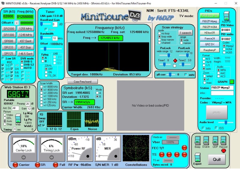 Receiving Digital Amateur Television (DATV) signals requires specialized software to interface with hardware tuners and decode the video stream. The _MiniTioune_ software, developed by F6DZP, serves this purpose, providing a Windows-based application for DVB-S and DVB-S2 reception and analysis. It is designed to work in conjunction with _MiniTiouner_ hardware, enabling hams to monitor DATV transmissions, including those from the QO-100 geostationary satellite. The resource outlines the initial setup process, including connecting the MiniTiouner hardware via a high-quality USB2 mini cable and running diagnostic test software. It details how to configure essential parameters such as symbol rate (SR), FEC rate, and DVB mode for various signal sources, from domestic satellite dishes to local DATV transmitters. Troubleshooting steps for common issues like "no video displayed" are also provided, often pointing to corrupted software filters or incorrect _Auto PID_ settings. Advanced features like the Web monitor for remote signal reporting and integration with _VLC_ media player for more tolerant decoding of non-DVB compliant signals are covered. The document also references a comprehensive user guide by W6HHC for the _MiniTiouner-Express_ system, which utilizes the same software, offering further in-depth assistance for operators.