Search results
Query: 2-element Yagi
Links: 26 | Categories: 0
-
 2-Element parasitic Yagis for the Shortwave-Bands 10-12-15-17-20-30m. The antennas are feeded with the DK7ZB-match. A quarter-wave choke of coax is grounded at the socket.
 -
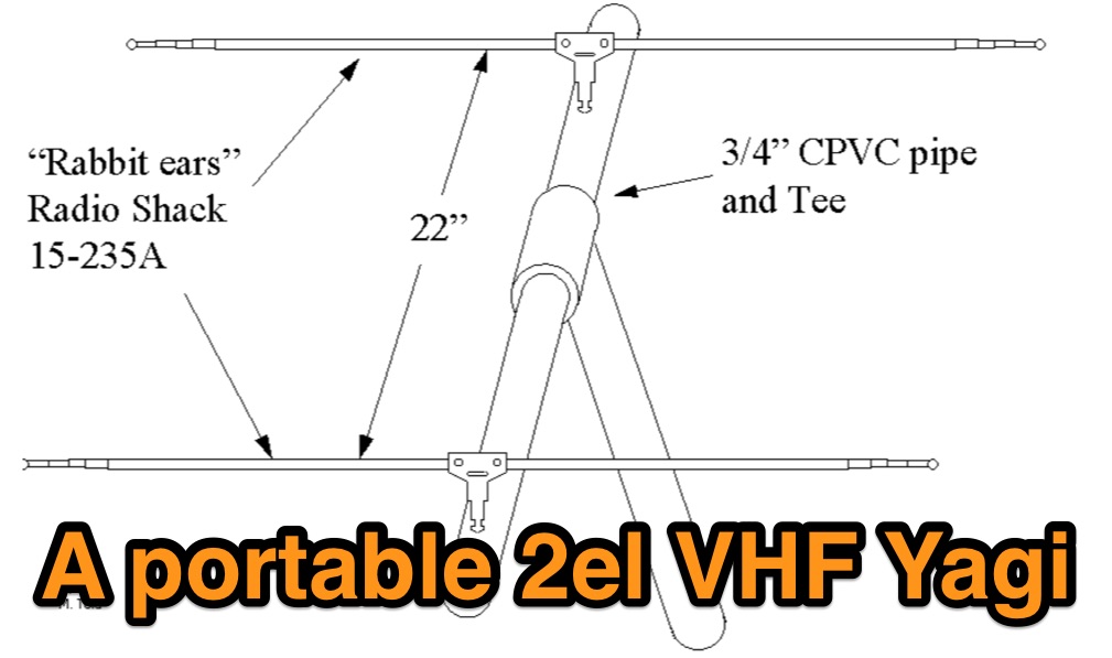 Build a portable VHF yagi antenna for 2 meters. All you need is two rabbit ear antennas from Radio Shack, two CATV baluns, four feet of 3/4 CPVC pipe with one tee.
 -
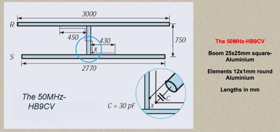 The HB9CV-Beam is a 2-Element-Yagi with two driven elements and was introduced by Rudolf Baumgartner, HB9CV in the 1950ies. This beam antenna is a coax-feeded version of the ZL-Special construction by DK7ZB for 2m, 6m and 10m
 -
 Presents a detailed construction guide for a 2-element _Moxon rectangle_ antenna optimized for the 10-meter band, designed by L. B. Cebik, W4RNL (SK). This resource demonstrates how to build a compact beam antenna using readily available hardware store aluminum tubing, fitting within a 12-13 foot width. It highlights the antenna's performance characteristics, including a gain comparable to a 2-element Yagi (11+ dBi) and a front-to-back ratio exceeding 20 dB between 28.3 and 28.5 MHz, with an SWR below 2:1 across the entire band. The design emphasizes direct 50-ohm coax connection without a separate matching system, though a 1:1 choke _balun_ is recommended. The guide provides practical advice on element construction, corner fabrication using L-stock or radius-bent tubing, and the critical side-to-side length adjustment for SWR optimization. It details the feedpoint assembly using a chassis-mounting coax connector and discusses element-to-boom plate options, including spar varnished plywood or LE plastic. The author's experience with a test model on a 20-foot mast confirms stable feedpoint characteristics and excellent performance even at lower heights. The document also includes insights into the antenna's free-space azimuth patterns, noting a broad forward lobe and significant front-to-back rejection. It contrasts the Moxon with traditional Yagis, positioning it as an effective, home-buildable alternative for compact sites or _Field Day_ operations, particularly beneficial during periods of increased 10-meter activity.
 -
 2-Element parasitic Yagis for the Shortwave-Bands 10m-30m
 -
-
 The ARRL ANTENNA Vol 5 COMPENDIUM features an article detailing two portable 6-meter antennas: a 2-element quad and a 3-element Yagi with telescoping elements. The 2-element quad exhibits a measured gain of **4.2 dB** over a dipole, while the 3-element Yagi achieves **5.8 dB** over a dipole. Both designs prioritize ease of construction and rapid assembly/disassembly for portable operations. Specific dimensions are provided for a 3-element 6-meter quad using #14 bare copper wire. The reflector element diameter is 6.2958 meters, the driven element 6.125 meters, and the director 5.8547 meters. Element spacing is 0.9398 meters between reflector and driven, and 1.1684 meters between driven and director. The SWR is under _1.26:1_ from 50 to 50.4 MHz, with a feed point impedance of 48.75 -j0.13 Ohms at 50.2 MHz, suitable for direct 50 Ohm coax feeding with a current _balun_.
 -
 This resource presents a detailed analysis of the W6NL 2-element 40-meter **Moxon Yagi** antenna, covering its design, construction, and measured performance characteristics. It outlines key specifications such as a free-space gain of 6 dBi, 11 dBi at 70 feet, and a direct 50-ohm feed. The document highlights the antenna's physical attributes, including 52-foot elements, a 27-foot boom, and a weight of 75 pounds, engineered to withstand 125 mph winds. Modeling was performed using **AO6** and K6STI software, with a focus on the unique functions of the transverse tip elements for Moxon coupling, physical balance, efficient capacitive loading, and reduced wind load. The presentation includes comparative data, showing the Moxon's superior front-to-back (F/B) ratio and wider bandwidth compared to traditional loaded Yagis. Performance graphs illustrate the SWR, gain, and F/B across the entire 40-meter band (7.0-7.3 MHz), comparing measured results against calculated values. Azimuth and elevation patterns demonstrate high F/B, with the antenna's pattern matching that of a full-size 3-element Yagi on a 30-foot boom. It also notes a gain difference of 1.5 dB down relative to a K3LR 4-element Yagi on a 50-foot boom, providing practical benchmarks for performance evaluation.
 -
 A 40-meter reversible _Moxon rectangle_ antenna project details its construction and performance, featuring 51-foot long sides and 7.7-foot turned-in sections. The design incorporates a 16.5-foot boom, with elements spaced 1.1 feet apart, constructed from #14 covered wire. It utilizes two double-pole relays for switching between NE and SW directions, achieving F/B ratios up to 40 dB on CW and 30 dB on SSB, with distinct reflector stub settings for each mode. This antenna replaced a full-size 2-element Yagi, demonstrating comparable forward gain while offering superior F/B ratios and directional flexibility. _EZNEC_ modeling indicates only 0.2 dB less forward gain than the Yagi. The system uses no baluns, relying on half-wave feedlines and switched stubs for impedance matching. The antenna is tree-supported at 45 feet, with its effective radiation height modeled at 80 feet due to local terrain, enhancing its performance over a nearby lake.
 -
 Designing a compact directional antenna for the 70cm band involves balancing gain, front-to-back ratio, and physical size. This resource details the construction of a 2-element Moxon rectangle antenna for 432 MHz, outlining the specific dimensions for the driven element and reflector, and discussing the advantages of its folded dipole configuration. The article provides insights into the historical context of 70cm operations and the author's personal experiences with early 432 MHz transceivers and antenna setups, such as a Jaybeam 48-element TV antenna. It also touches upon the practical aspects of building and deploying such an antenna for local and weak-signal work. The Moxon antenna design is compared to a 3-element Yagi, noting its superior front-to-back ratio and broader bandwidth for a given boom length, making it suitable for portable operations or restricted spaces. The construction uses readily available materials like copper wire and PVC tubing, emphasizing simplicity and ease of replication. Performance characteristics, including a reported gain of approximately 5.5 dBi and a front-to-back ratio of 20 dB, are discussed in the context of its compact footprint. The resource includes a visual representation of the antenna's dimensions and construction, aiding in practical implementation.
 -
 A simple to build Yagi 2 element antenna for 15 or 20 meters band by 9m2mso
 -
 The N0KHQ Coax Square antenna, designed for 17 meters and built using RG-58 coaxial cable, presents an intriguing option for hams with limited space. L. B. Cebik, _W4RNL_, meticulously models and analyzes this array, clarifying its classification not as a modified Moxon, but as a distinct member of the "dual-coupled, 2-element, parasitic array" family. The design leverages the velocity factor of RG-58 (approximately 0.66-0.67) to achieve significantly shorter element lengths compared to full-size counterparts, resulting in a perimeter of 42 feet for the N0KHQ array versus 54 feet for a standard Moxon. _NEC_ modeling reveals the coax square's performance characteristics, including a forward gain of 5.6 dBi and a 23.7 dB front-to-back ratio on 18.118 MHz. While slightly less gain than a Moxon (6.0 dBi), its pattern exhibits Yagi-like nulls at 90 degrees, distinguishing it from the Moxon's wider beamwidth. The article also delves into the unique feedpoint considerations, explaining how the split braid and center conductor of the RG-58 driver effectively form a folded dipole, allowing for impedance transformation to achieve a good match for 50-Ohm cable. Despite its shortened elements, which inherently narrow the operating bandwidth, the coax square maintains satisfactory performance across the 17-meter band. The analysis emphasizes that while SWR curves are important, a holistic view of gain and pattern degradation across the band is crucial. This antenna is a viable solution for operators needing a compact, directional array, particularly for narrow bands like 17, 30, or 12 meters, where its high-Q performance is most effective.
 -
 For radio amateurs seeking compact, directional antenna solutions, the Moxon Rectangle offers an attractive alternative to traditional two-element Yagis. This resource compiles several articles by L. B. Cebik, W4RNL, exploring the **Moxon Rectangle** design, which provides gain comparable to a full-size two-element array but with a significantly improved **front-to-back ratio** and a direct 50-Ohm feedpoint match. The collection covers both wire arrays, particularly for lower HF bands, and rotatable aluminum beam constructions, addressing various aspects of this popular antenna configuration. The articles delve into specific band applications, including designs for 10 meters, 40 meters, and 2 meters, alongside discussions on multi-banding techniques and pattern characteristics. Comparisons are drawn between the Moxon and other antenna types, such as VK2ABQ Squares, highlighting the Moxon's advantages in terms of size and performance. Practical construction notes are provided for both wire and aluminum versions, offering insights into building these antennas for different operating environments.
 -
-
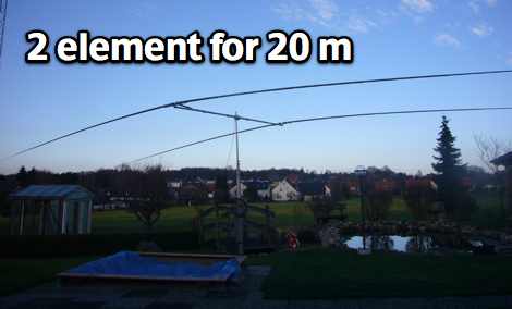
 A 20-meter Moxon antenna design provides a compact directional solution for the 14 MHz band, achieving approximately **5.5 dBi** of forward gain and a front-to-back ratio exceeding 20 dB. This rectangular wire array, consisting of a driven element and a reflector, offers a smaller footprint than a traditional 2-element Yagi, making it suitable for space-constrained installations. Construction details focus on specific dimensions for the wire elements, fed with 50-ohm coaxial cable. The _Moxon rectangle_ inherently delivers wide bandwidth and a clean radiation pattern, simplifying tuning with a relatively low SWR across the entire 20-meter band. Its robust performance makes it a practical choice for both fixed stations with limited tower space and portable _DXing_ operations. The design's characteristics are particularly beneficial for contesting and long-haul communications on 20 meters.
 -
 The Moxon Beam, introduced by L. Moxon (G6XN), is a compact 2-element Yagi featuring a radiator and reflector with reduced dimensions, approximately 75% the size of a full-size beam. This design utilizes bent element ends for capacitive loading, which is superior to inductive loading with coils, resulting in greater bandwidth and lower losses. DK7ZB details that while the gain is slightly lower (0.5-0.7 dB) than a full-size beam, the _Moxon_ offers an exceptional front-to-back (F/B) ratio of 30 dB or more on its design frequency, surpassing other 2-element beams. The article provides specific dimensions for building wire _Moxon_ antennas for bands from 30m down to 10m, and also mentions a 2-m-Moxon. Construction guidance includes using fishing rods for lightweight spreaders and an aluminum tubing spider for support. The resource highlights the utility of _Moxgen_ by AC6LA, a freeware program that simplifies Moxon beam design and generates EZNEC output files for further analysis and tapering modifications. DK7ZB emphasizes that the design frequency should be set at approximately one-third from the band's beginning to optimize SWR performance, as SWR tends to rise more significantly below the design frequency. The bandwidth for SWR < 1.5 is noted as sufficient for ranges like 28.0-28.7 MHz and 21.0-21.45 MHz when constructed with aluminum tubes, though wire beams exhibit a narrower bandwidth.
 -
 Constructing an effective directional antenna for the 40-meter band presents unique challenges due to its physical size requirements. This resource details the homebrew construction of a 2-element _Moxon_ Yagi antenna specifically designed for 7 MHz operation. The author, TA7OM, provides a visual guide to building this antenna, showcasing the boom, element mounting, and feedpoint connections through a series of high-resolution photographs. While textual descriptions are minimal, the imagery clearly illustrates the mechanical aspects of the antenna's assembly. The _Moxon_ rectangle design offers a compact footprint compared to a full-size Yagi, making it a practical choice for many hams with limited real estate. The visual documentation allows builders to replicate the antenna's structure, including the use of PVC pipe for element support and the method for spacing the driven and reflector elements. The project emphasizes practical construction techniques for achieving a directional pattern on a challenging HF band, suitable for DXing and contesting.
 -
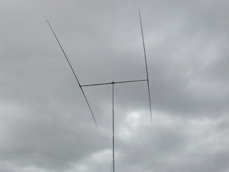 This antenna was designed for the CQ WW CW 2009 at EA8URL. All elements are made out of fishing rods with an insulated copper cable fixed on the rods by cable ties. Both fishing rods and cable are UV resistant.
 -
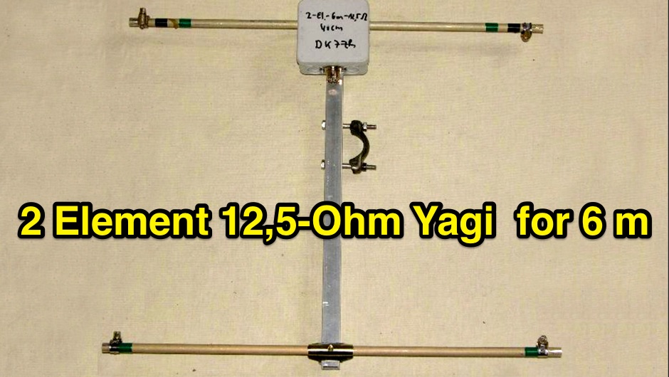 2-Element-12,5-Ohm-Yagi with 0,40m-Boom complete description of all details for building this Yagi and stacking to an array
 -
 The F5GIT blog documents the amateur radio pursuits of Tony, F5GIT, offering insights into his DXpedition experiences and contest operations. It presents detailed accounts of his participation in events like the _CQ WW DX Contest_ and the _IARU HF Championship_, often including specific callsigns worked and operational strategies employed. The resource covers various aspects of station setup, antenna configurations, and radio equipment used for achieving contacts across different bands. Content includes discussions on antenna performance, such as a **2-element Yagi** for 10/15/20 meters, and operational challenges encountered during remote or portable setups. The blog also serves as a personal log, chronicling significant QSOs and providing a historical record of his amateur radio journey. It details specific locations operated from, like _Île de Ré_, and the unique challenges presented by such environments. Furthermore, the blog provides practical information on optimizing station efficiency and maximizing contact rates during high-intensity operating periods. It reflects a dedicated approach to improving radio skills and contributing to the global amateur radio community through active participation and sharing experiences.
 -
 The resource examines the operational characteristics and potential of Moxon Yagi antennas, drawing insights from Les Moxon's work and subsequent NEC modeling. It presents simulated current distributions and radiation patterns for a 40-meter Moxon, comparing its performance against a standard 2-element Yagi on the same band. Specific data points include forward gain, front-to-back (F/B) ratio, and feedpoint impedance, which are critical parameters for antenna design and optimization. Further analysis extends to a 20-meter Moxon, detailing its gain, F/B ratio, and SWR bandwidth across the band. The discussion highlights the Moxon's compact footprint and its ability to achieve respectable performance metrics, making it a viable option for hams with limited space. The content provides a technical assessment of the Moxon's advantages in terms of pattern purity and impedance stability compared to other compact directional arrays. The article also touches upon the practical considerations for constructing and deploying Moxon antennas, emphasizing the trade-offs between physical size and electrical performance. It includes graphical representations of antenna currents and radiation patterns, offering visual aids to understand the theoretical concepts discussed.
 -
 A page with an embedded video about a two elements yagi antenna for 28 MHz based on the original antenna design by VE7CA
 -
 Documents S21RC's construction of an impedance transformer harness for a VHF/UHF cross yagi, utilizing 20m of _RG179_ cable. Details the creation of a DIY RF sampler with a -50dB sampling output, primarily for measuring HF radio PA section output with a Spectrum Analyzer, also applicable for _Pure Signal_ transmission. Chronicles the deployment of a 200m long beverage antenna for the _S21DX IOTA_ operation in 2022, positioned 2m above ground. Discusses the construction of a 3-element short beam for 10m to replace a previous 2-element antenna, with assistance from S21DW. Provides guidance on operating cheap _PA-70_ and _PA-100_ type Chinese SSPAs using IRF530 MOSFETs, emphasizing the necessity of a final LPF. Outlines the design and construction of a fully isolated interface for radio-to-computer connections, supporting various digital modes with isolated ground, audio transformers for IN/OUT, optical isolation for CAT/CIV, and isolated PTT/COS lines. Includes a log of software updates, such as the _HMI/TFT for NX8048K070_ and _2.1.14 Lite_ release with bug fixes for PEP hold and gradual watt decay.
 -
 The DK7ZB-Dualband-Moxon-Beam provides a compact, high-performance antenna solution for 28 MHz and 50 MHz operations, utilizing a single 50-ohm feedpoint. This design functions as a mini-beam on 10 meters, achieving a gain of **4.0 dBd** with a front-to-back ratio of _30 dB_, while operating as a 2-element Yagi on 6 meters, yielding a gain of **4.3 dBd** and an 11 dB F/B ratio. The antenna's dimensions are approximately two-thirds that of a full-size 10-meter beam, making it suitable for smaller spaces. Construction details include a parts list specifying aluminum tubes of various diameters and lengths for the reflector and radiator elements. Builders like Aleks (S54S) and Marcio (PY2OK) have successfully replicated the design, with Aleks noting the utility of bending corners during assembly. Fine-tuning is accomplished by adjusting the length of specific elements that slide into larger tubes. The feeding system incorporates a balun, with options for either 300 watts using RG188 on an FT140-43 core or 1 kilowatt using _Aircell-5_ on an FT240-43 core, ensuring versatility for different power levels.
 -
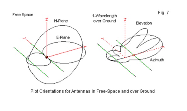 Method, Units of Measure, and the Dipole Standard of Reference. This article helps in understanding where does beam gain come from in directional aerials like in example Yagi antennas.
 -
 This page discusses the construction and design of a shortened 2-element Yagi antenna for the 40-meter band, focusing on the driven element. The author shares insights on adding hats to the coil to reduce losses and improve performance. The article also mentions the use of EZNEC modeling software and an AIM4170 analyzer for tuning. Amateur radio operators interested in such antenna design and optimization for the 40-meter band can find useful information and practical tips on this page.