Search results
Query: 20m 10m antenna
Links: 41 | Categories: 0
-
 A 10-20 meters coverage delta loop antenna. After relocating, DL2HCB designed a multiband loop antenna to cover 10-20m with an open-wire feed for impedance matching and compact installation. Inspired by the mini-X-Q design, a modified 10m delta-loop was built, enhanced with a 1/4 wave shorted stub for 28 MHz using 450-ohm ladder line. The antenna delivers east-west broadside radiation and performs as a closed loop on other bands. Operational tests yielded strong European signals and successful DX contacts, including a 20m QRP QSO with FY/DJ0PJ.
 -
 The G5RV antenna, with an overall length of **31.10m (102ft)**, functions as a 3/2-wave on 20 meters when installed horizontally at 12m (39ft), exhibiting a resonant frequency of 14.150MHz and an approximate resistance of 80 ohms. Its 10.36m (34ft) stub line, designed as a 1/2-wave on 14.150MHz with a 0.97 velocity coefficient, acts as an impedance transformer across other bands, aiming for multiband operation without traps. On 20m and higher frequencies, the G5RV demonstrates improved gain compared to a standard dipole, attributed to the _collinear effect_ from multiple 1/2-waves along the wire. The original design sought a multiband solution for limited spaces, often requiring an Antenna Tuning Unit (ATU) for effective operation across bands like 80, 40, 30, and 20m, particularly with modern solid-state PAs. Variants, such as the F8CI modification, incorporate a 1/4 current balun at the stub line's base for symmetrical-to-asymmetrical transition, known as a _remote balun_. Proper flat-top or inverted-V installation is critical for maintaining symmetry and collinear gain, with inverted-V apex angles below 120° progressively diminishing higher-band performance.
 -
 GAP Titan DX Evaluation, antenna for 10m 15m 20m 40m 80m
 -
 This multiband wire antenna it is an off centre fed dipole, with 10 feet of vertical radiator, needs no tuner on 40m, 20m and 10m and works fine on all bands above 40m with a tuner, and even below 40m on 60m, and 80m.
 -
 Multiband Center-Loaded Off-Center-Fed Dipole (CL-OCFD) antenna that work on 80m 40m 30m 20m 15m 10m. The Center-Loaded Off-Center-Fed Dipole (CL-OCFD) antenna, developed by Serge Stroobandt, offers a versatile solution for amateur radio enthusiasts, covering multiple HF bands (80, 40, 30, 20, 15, and 10 meters) without the need for an antenna tuner. This innovative design utilizes a capacitor for resonance on the 80-meter band and a resistor to manage static charges. The CL-OCFD enhances bandwidth and simplifies operation, making it a significant advancement on OCF Dipole design.
 -
 Demonstrates the construction and performance of an updated ZS6BKW multiband dipole, a variant of the _G5RV_ antenna, specifically designed for HF operation. The article details a real-world installation using 13.5m copper wire elements and 12.2m of 450 Ohm ladder line, configured as a sloping inverted-V with the apex at 10m and ends at 4m above ground. It covers the critical aspect of impedance matching, incorporating an 8-turn choke balun at the feedline transition to RG-58U coax to mitigate RF common mode current. Measurements confirm favorable SWR readings below **1.3:1** on 7.1 MHz, 14.11 MHz, 18.06 MHz, and 24.8 MHz, indicating effective resonance across 40m, 20m, 17m, and 12m bands. The installation also shows usable SWR dips on 3.55 MHz (5:1), 29.02 MHz (2:1), and 50.84 MHz (3:1), extending its utility to 80m, 10m, and 6m with an antenna tuning unit. Initial on-air results report clear reception of stations over **5000km** away, validating its DX potential.
 -
 The ZS6BKW multiband HF antenna, a design by ZS6BKW (G0GSF), functions effectively on multiple HF bands without requiring an Antenna Tuning Unit (ATU) for 40, 20, 17, 12, 10, and 6 meters. This antenna, approximately **27.51 meters** (90 feet) long with a 12.2-meter (40-foot) open-wire feeder, is a direct descendant of the _G5RV_ but offers superior multi-band resonance. It can be deployed as a horizontal dipole or an inverted-vee, with the latter requiring only a single support and maintaining an apex angle of at least 90 degrees to prevent signal cancellation. Performance data, recorded with an MFJ Antenna Analyser, indicates SWR values of 1:1 on 7.00 MHz (40m) and 14.06 MHz (20m), with SWR below 1.3:1 on 17m, 10m, and 6m. While primarily designed for these bands, the antenna can be adapted for 80m, 30m, and 15m with an ATU, preferably at the balanced feeder's base. The use of 450-ohm twin-lead for the feeder is recommended over 300-ohm for improved strength and reduced losses, especially in adverse weather conditions. This design, originally published in _RadCom_ in 1993 and featured in Pat Hawker’s "Antenna Topics," provides a compact and efficient solution for HF operation, particularly for those with limited space or resources.
 -
 The **NW3Z** optimized wideband antenna designs, originally presented at Dayton 2001, detail Yagi configurations for the 20-meter, 15-meter, and 10-meter amateur radio bands. This resource provides access to the design files, likely containing critical parameters such as element spacing, element lengths, and boom dimensions, which are essential for replicating these directional antennas. The designs focus on achieving wide bandwidth, a desirable characteristic for contesters and DXers operating across a significant portion of each band. The content specifically references "nw3z-Antenna-DesignsDownload," indicating that the core information is available as a downloadable file, presumably in a format suitable for antenna modeling software or direct construction. Such files typically include **NEC models** or similar data, allowing for performance analysis and optimization before physical construction. The emphasis on "optimized wideband" suggests design considerations for SWR bandwidth and gain characteristics over a broader frequency range than typical narrow-band Yagis. The resource serves as a direct source for specific, proven antenna designs from a known amateur radio antenna designer, offering practical data for hams interested in building high-performance Yagi arrays for HF.
 -
 This wire-beam has one radiator-element, feeded with 450-Ohm-Wireman-twinlead and needs an antenna-tuner. For the bands 6m, 10m, 12m, 15m, 17m and 20m bended reflector-elements are used. The support is a cross of 4 fibreglass-fishing-rods
 -
 F6EZX presents a detailed account of constructing a compact, multi-band _Levy antenna_ for portable holiday operations, specifically addressing issues with local QRM from a previous _Deltaloop_ setup. The article outlines the design criteria, including multi-band operation on 40m, 30m, 17m, 15m, 12m, and 10m, a symmetrical configuration to reduce interference, and a low take-off angle for DX. Construction involves 2x 10.3m radiating elements and a 15.3m open-wire feeder (ladder line) with 7cm spacing, made from 1.5mm2 copper wire and foam pipe insulation spacers. Theoretical calculations, referencing F9HJ's "_Les antennes Levy_" book, guide the determination of element lengths and feeder impedance characteristics, aiming for a good match across bands with a commercial antenna tuner. Initial field tests with the _VCI Vectronics VC300DLP_ tuner showed a 1:1 SWR from 80m to 10m, with some difficulty on 17m. The antenna, mounted as a 45-degree slopper with the high point at 12m, successfully facilitated DX contacts to South America, particularly Chile and Argentina, suggesting a lower take-off angle compared to the previous Deltaloop which favored Brazil. The Levy antenna significantly reduced TVI/RFI, attributed to its improved symmetry and greater distance from the QRA. While signal reports on 15m and 20m were 1-2 S-points lower than the Deltaloop, its performance on 40m and 30m was comparable, fulfilling the design goals for a portable, low-cost, multi-band solution.
 -
 Presents G0GSF Brian's ZS6BKW antenna, a refined iteration of the classic G5RV, offering improved performance across multiple HF bands. The design emphasizes specific radiator and ladder line lengths to achieve lower SWR on 40m, 20m, 17m, 12m, and 10m, making it a practical choice for operators seeking a single wire antenna solution. The document includes critical dimensions for the flat-top and the 450-ohm ladder line section, which are key to its multiband resonance characteristics. Unlike the original G5RV, the ZS6BKW aims for direct 50-ohm feedpoint impedance on several bands, reducing the need for an external antenna tuner. My field experience with similar optimized dipoles confirms that precise construction, particularly the ladder line length, is paramount for realizing the intended SWR benefits. This design offers a compelling alternative for hams with limited space or those preferring a less complex antenna system.
 -
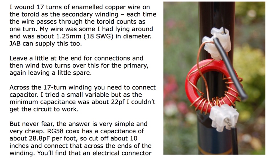
 Constructing an HF End-Fed Half-Wave (EFHW) vertical antenna, the resource details the winding of a monoband matching unit, inspired by _AA5TB_, designed to provide a 50 Ohm impedance match without a ground plane or antenna tuner. It specifies the use of a _T200-2_ ferrite core for the transformer, outlining the 13-turn secondary and 2-turn primary winding process with enamelled copper wire. The document also describes the integration of a coax capacitor, whose length is critical for tuning and varies by band, with specific starting lengths provided for 20m, 17m, 15m, 12m, and 10m operation. The practical application section guides the builder through tuning the antenna using an antenna analyzer, emphasizing the iterative process of spacing secondary windings and trimming the coax capacitor to achieve resonance at the desired band frequency. It highlights the antenna's low angle of radiation, beneficial for DX, and claims up to 2 S-points improvement over a _G5RV_ or similar doublet when used as an omnidirectional vertical. A comprehensive shopping list, including specific part numbers from _Rapid Electronics_, is provided, along with advice on selecting fiberglass fishing poles for support and suitable antenna wire.
 -
 A simple and low cost multiband vertical hf antenna covering 5 bands (20m-10m) from an old CB antenna
 -
 5 Band 1/4 wave Telescopic Antenna. The 20m to 10m, antenna is simple and cheap to make, and has a performance that matches commercial antennas but at cost considerably lower. The design was purposely based on a telescoping fibre glass fishing rod as this allows it to be easily stowed away in the car.
 -
 A 5-band (20m-10m) HF antenna - Just 7ft square and great for a small garden. Build it yourself for around 60 GBP.
 -
 The 6 Band Inverted L Antenna MK3 is a versatile multiband antenna designed for amateur radio operators. This antenna covers 160m, 80m, 40m, 20m, 15m, and 10m bands, making it suitable for a wide range of HF communications. The design is based on a W3DZZ configuration, incorporating traps for optimal performance. The MK3 version features a sturdy 5/8th CB mast, replacing the original timber mast, which enhances durability against harsh weather conditions. The antenna's construction allows for effective operation, particularly on the 40m band, where it has been successfully used to contact distant locations including ZL, VK, and Antarctica. Constructing this antenna requires careful attention to detail, especially regarding the radials and grounding. The traps resonate at specific frequencies, and additional resources are available for building coaxial traps. The antenna is designed to work efficiently without an ATU on the lower bands, while higher bands may require tuning. This project is ideal for both beginner and intermediate operators looking to enhance their station with a reliable multiband antenna.
 -
 The Chameleon V1 HF Multiband Antenna is a mobile antenna that can also be used as portable. Lightweight mil whip antenna system with 10 BANDS capability 6m, 10m, 12m, 15m, 17m, 20m, 30m, 40m, 60m & 80m.
 -
 The ZS6BKW wire antenna, a variant of the G5RV, utilizes a specific 13m (42.6 ft) length of 450-ohm window line as its matching section, feeding a 28.5m (93.5 ft) flat-top element. This design aims for lower SWR on 40m, 20m, 17m, 12m, and 10m compared to a standard G5RV, often achieving SWR values below 1.5:1 on these bands without an antenna tuner. The feedpoint impedance transformation provided by the window line allows for direct connection to 50-ohm coax on multiple bands. F4FHH's experience involved constructing the ZS6BKW and evaluating its performance against an _OCF dipole_ (Off-Center Fed) on various HF frequencies. The article includes observations on SWR readings and operational effectiveness, highlighting the ZS6BKW's suitability for multi-band operation. The antenna's overall length, including the flat-top and window line, is approximately **41.5 meters** (136 feet), making it a significant wire antenna for fixed station use. Comparative analysis with the OCF dipole provided practical insights into the ZS6BKW's advantages and limitations, particularly concerning bandwidth and tuner requirements.
 -
 A monoband end-fed half wave for 10m, 20m or any other HF band, includes a PDF with detailed information to build your own monoband or multiband antenna
 -
 A simple beam antenna offering good performances on 3 bands by 9m2mso
 -

-
 A simple 7 bands off-center dipole wire antenna designed to work on 80 meters band and that can cover also 40m 30m 20m 15m 12m 10m with acceptable SWR
 -
 Demonstrates the product line of _LZ Antenna Ltd._, a Bulgarian manufacturer specializing in amateur radio antennas and custom electronic devices. The company focuses on robust, high-quality HF multiband Yagi and vertical antennas, leveraging over 20 years of experience from founder Georgi Georgiev in radio amateur development. Featured models include the LZA 8-4, LZA-10-3, and the LZA-7-3A WRTC 2022, alongside various rotary dipoles like the LZA1 40/30m. Provides specifications for several Yagi antennas, such as the LZA-9-5, LZA-13-7, and LZA-6-3 (a 6-element, 3-band design). The company emphasizes applying "leading edge technology" to high-frequency communication equipment production, with products designed for durability and performance. The LZA-10-5 Yagi offers **12.5 dBi** gain on 10m, while the LZA-13-7 provides **13.2 dBi** on 20m, showcasing competitive gain figures for DXing and contesting.
 -
 The ZS6BKW antenna, a popular multiband wire antenna, offers improved band matching compared to the traditional G5RV. This construction guide details the process, beginning with specific dimensions: 13.11 meters (43 feet) for the 450-ohm ladder line and initial dipole arm lengths of approximately 14.8 meters each. It emphasizes the critical role of an _antenna analyzer_ for accurate tuning, particularly for determining the velocity factor of the ladder line and achieving a 1:1 impedance match. The article outlines the materials required, including a 1:1 current balun, 450-ohm window line, wire for the dipole arms, and a 50-ohm non-inductive resistor for testing. It provides a step-by-step procedure for cutting the ladder line to its electrical half-wavelength, explaining how to calculate the velocity factor using measured and free-space frequencies. For instance, a measured 50-ohm impedance at 12.54 MHz with a calculated free-space half-wavelength frequency of 11.44 MHz yields a velocity factor of 0.91. Final adjustments involve hoisting the antenna to its operational height and fine-tuning the dipole arm lengths to achieve optimal SWR, specifically targeting 14.200 MHz. The _ZS6BKW_ design is noted for its performance on 80m, 40m, 20m, 10m, and 6m, though it is not optimized for 15m operation. The author, _VK4MDX_, shares practical tips for durable construction using stainless steel wire and cable clamps.
 -
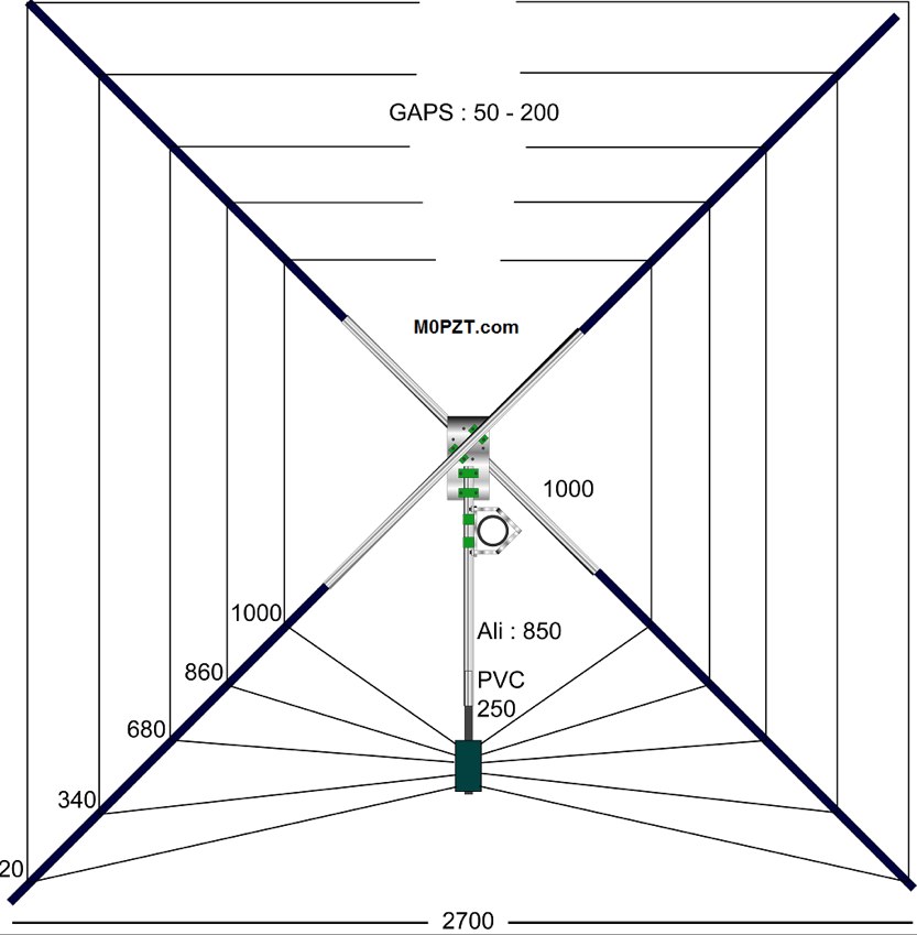
 Demonstrates the design and construction of a compact, portable multi-band mini-delta loop antenna, specifically optimized for /P (portable) operations from remote locations like Scottish islands. The resource covers the theoretical underpinnings of half-wave loops, contrasting closed and open configurations, and then details the application of a folded dipole principle to achieve a 50-ohm match for direct coax feed. It presents empirical formulas for calculating element lengths, considering the velocity factor of common wire types, and provides a detailed example for a 20m (14.175 MHz) version. The article includes a comprehensive table of dimensions and allowances for a five-band (20m, 17m, 15m, 12m, 10m) mini-delta beam, along with construction hints for the central support and balun. It specifies a 1:1 trifilar balun wound on a ferrite rod and describes the antenna adjustment process using an _MFJ-259B Antenna Analyser_. Initial test results indicate an SWR of 1:1 at resonance and a bandwidth of approximately 240 kHz on 20m, even at a low height of five feet above ground. The distinctive utility lies in its focus on a practical, easily deployable beam antenna for portable DXing, offering a viable alternative to more complex or larger arrays.
 -
 The Vee Beam antenna project presents a versatile solution for hams, enabling operation across all eight High Frequency bands (80m to 10m) with significant gain on 20m to 10m. This easy-to-construct antenna utilizes two long wires at an angle, enhancing directional performance and minimizing ground losses. With a low visual profile, it is discreet and effective for various applications. The design allows for optimal leg lengths and included angles, ensuring robust performance while maintaining simplicity in construction and operation. The V Beam antenna is an aerial that you can use on all eight High Frequency amateur bands (80, 40, 30, 20, 17, 15, 12 and 10m) with an antenna tuner, and which gives significant gain on the five bands from 20 to 10 meters band.
 -
 Construction details and tests about a 2 elements cubical quad antenna for HF Bands (20,17,15,12 and 10m band).
 -
 An off centre fed dipole, with 10 feet of vertical radiator. It needs no tuner on 40m, 20m and 10m by M0UKD
 -
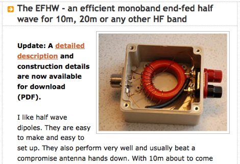 An efficient monoband end-fed half wave for 10m, 20m or any other HF band
 -
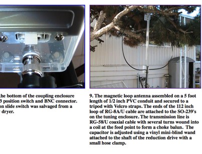 Here is a well documented plan of a 20m-10m compact magnetic loop antenna. Article includes lots of pictures and technical details published by KP4MD
 -
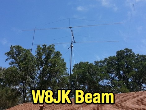 A compact 2 element W8JK beam antenna for 20M to 10M bands by AF6SA
 -
 Constructing an End-Fed Half-Wave (EFHW) antenna offers a practical solution for HF operators seeking a multiband wire antenna without the need for extensive radial systems. This design typically employs a high-impedance transformer at the feed point, matching the antenna's inherent high impedance to a 50-ohm coaxial feedline. The article specifically details a 2012 approach, focusing on a transformer with a 49:1 turns ratio, which is a common configuration for EFHW antennas. The resource outlines the construction of a wire element cut for a half-wavelength on the lowest desired band, with specific coil arrangements enabling operation on harmonically related bands such as 40m, 20m, and 10m. It discusses the physical dimensions and winding details for the matching transformer, often utilizing a ferrite toroid core to achieve the necessary impedance transformation. The content provides insights into the operational principles and practical considerations for deploying such an antenna, including methods for tuning and optimizing performance across multiple amateur radio bands. While acknowledging that the presented information from 2012 may be superseded by newer insights, it serves as a foundational reference for understanding EFHW antenna theory and construction.
 -
 Documents S21RC's construction of an impedance transformer harness for a VHF/UHF cross yagi, utilizing 20m of _RG179_ cable. Details the creation of a DIY RF sampler with a -50dB sampling output, primarily for measuring HF radio PA section output with a Spectrum Analyzer, also applicable for _Pure Signal_ transmission. Chronicles the deployment of a 200m long beverage antenna for the _S21DX IOTA_ operation in 2022, positioned 2m above ground. Discusses the construction of a 3-element short beam for 10m to replace a previous 2-element antenna, with assistance from S21DW. Provides guidance on operating cheap _PA-70_ and _PA-100_ type Chinese SSPAs using IRF530 MOSFETs, emphasizing the necessity of a final LPF. Outlines the design and construction of a fully isolated interface for radio-to-computer connections, supporting various digital modes with isolated ground, audio transformers for IN/OUT, optical isolation for CAT/CIV, and isolated PTT/COS lines. Includes a log of software updates, such as the _HMI/TFT for NX8048K070_ and _2.1.14 Lite_ release with bug fixes for PEP hold and gradual watt decay.
 -
 This page delves into the Inverted V antenna, a source of myths among ham radio operators. The author explores the behavior of this antenna type with a focus on a 20m half-wave dipole positioned 10m above the ground. From Pythagoras to high school math, the article simplifies the calculation of dimensions and angles for setting up an Inverted V antenna. It includes a spreadsheet for calculating hypotenuse length and angles, crucial for antenna setup. Additionally, it provides insight into the radiation pattern of a 'flat' half-wave dipole at 10m height. Useful for hams planning to optimize their antenna setup. In Norwegian.
 -
 Operating as FY/F5UII, Christian F5UII conducted a DXpedition to French Guiana (FY) from January 13 to 30, 2013. The primary operation utilized the FY5KE radio club station in Kourou, with activity focused on voice modes during specific weekday hours. The resource details the operator's intent to transmit before 12:00z and after 22:00z, or as availability permitted, from the mainland. A significant aspect of this operation involved a dedicated weekend activation of the Salut Islands, specifically **IOTA SA-020**, from January 19-20, 2013. This segment of the DXpedition was conducted from Royal Island (Ile Royale), part of a group including Devil's Island (Ile du Diable) and St. Joseph Island (Ile Saint Joseph), located 14 km offshore from Kourou. The station setup for the IOTA activation included 100 Watts of power, a GPA-030 vertical antenna for 10m, 15m, and 20m, and dipole antennas for 17m and 40m, with antenna deployment contingent on site conditions and propagation. The operator anticipated strong interest for the SA-020 entity.
 -
 This article documents the author's journey in building, modifying, and testing a DIY short vertical antenna for 40, 30, and 20 meters, with potential 80m capability. Initially inspired by Parks On The Air (POTA), the author explores pedestrian mobile operation and details various experiments to enhance antenna performance. The piece highlights challenges, SWR tuning, portability, and practical results, emphasizing a balance between efficiency and size. Ultimately, it showcases the adaptability of DIY antennas for portable ham radio applications.
 -
 This study details a reception comparison between vertical and horizontal active loop antennas, specifically two identical _Wellgood active loop antennas_, on various HF bands. The experiment, conducted in a densely populated QRM-prone area, monitored FT8 signals over a 24-hour period using two identical receivers. The methodology involved direct comparison of signal reception across the HF spectrum, aiming to identify performance differences based on antenna orientation. The results indicate that vertical loops demonstrated superior performance on higher bands (10m, 15m, 20m), while horizontal loops excelled on lower bands (30m, 40m, 160m), particularly for receiving long-distance (DX) signals. The horizontal loop's advantage on lower bands is attributed to potentially better low-angle performance and reduced sensitivity to man-made noise, yielding a **2-3 S-unit** improvement on 160m. The study provides practical insights for optimizing antenna placement in challenging urban environments, noting that the horizontal loop consistently showed a **10-15 dB** signal-to-noise ratio improvement on lower bands.
 -
 WB8LZR details the construction and initial field results of a multi-band vertical wire antenna, designed to complement his existing horizontal loop for improved DX on 80 meters. The antenna utilizes a 67-foot vertical wire, configured as a quarter-wave radiator on 80m, and employs a 1:1 current balun for RF isolation on 80m, 30m, and 17m. For bands like 40m, 20m, and 10m, where the wire acts as a half-wave or full-wave radiator, an additional impedance transforming _unun_ is integrated to manage the significantly higher feedpoint impedance and voltage. The author notes the vertical's performance as a receiving antenna, observing reduced noise compared to his main horizontal loop, particularly on 80m, and even hearing some long-path signals the loop missed. Initial QRP contacts, including a **1-watt** QSO with a _VP2 station_ on 30m, demonstrate its transmit capability. While the radial system is currently rudimentary, the project outlines practical considerations for multi-band vertical deployment and impedance matching.
 -
 From March 2 to March 11, 2018, a Norwegian team operated as Z2LA from Zimbabwe, focusing on 160m through 10m bands using SSB and CW modes. The operation, described as "holiday style," aimed to provide contacts for DXers worldwide seeking a rare DXCC entity. Key equipment included a SUNSDR PRO II, an Elecraft KX3, and an Icom 706 MK2G as a spare radio, supported by two Juma 1000 amplifiers for robust signal output across the bands. Antenna systems were tailored for multi-band operation, featuring an Inv L for 160m and 80m, sloping dipoles for 30m/40m, and a _Hexbeam_ from SP7IDX Technology covering 20m to 10m. For improved reception, the team deployed a SAL 30, two reversible BEV antennas from remoteqth.com, and a BOG from K1FZ, enhancing their ability to hear weak signals. QSL information directs operators to Clublog for log search and M0OXO Charles for OQRS, explicitly requesting no bureau cards. The team comprised LA7THA Rune, LA7WCA Arne, and LA9VPA Thor, successfully making numerous contacts and contributing to the DX community's pursuit of _Zimbabwe_ as a DXCC entity.
 -
 The Shrunken Quad antenna is a unique design that offers full-sized performance on the 10m and 15m bands while incorporating linear loading via a trap for operation on the 20m band. This design allows for effective communication in the HF spectrum, making it suitable for both casual operators and serious DXers. The quad configuration provides excellent gain and directivity, which is beneficial for contesting and long-distance contacts. Constructing the Shrunken Quad involves careful attention to dimensions and materials to ensure optimal performance. The antenna's compact nature makes it an excellent choice for limited space situations, allowing operators to enjoy the benefits of a quad without the need for extensive real estate. This project is ideal for amateur radio enthusiasts looking to enhance their station's capabilities with a versatile and efficient antenna system.
 -
 This project details the design and construction of a Spider Quad antenna for HF bands (20m, 17m, 15m, 12m, and 10m). The boomless structure optimizes driver and reflector spacing, enhancing performance. Tuning and impedance matching were refined using antenna analyzers and a 1:2 balun. Final tests confirmed excellent SWR and gain, making this an efficient solution for top performance DXing.