Search results
Query: PIC microcontroller
Links: 21 | Categories: 2
-
 The project details a DIY SWR/Wattmeter designed around an _Arduino Uno_ shield, providing capabilities to measure RF power from 2 to **200 watts** and Standing Wave Ratio (SWR) for HF amateur radio bands. This construction features a compact design, integrating the measurement circuitry directly onto a custom PCB that interfaces with the Arduino Uno microcontroller. Key components include a directional coupler for sensing forward and reflected power, precision rectifiers, and analog-to-digital conversion for processing RF signals. The Arduino firmware handles calibration, calculations, and displays the results on an integrated LCD, offering real-time feedback on antenna system performance. The design prioritizes simplicity for homebrewers. Performance specifications indicate accurate readings within the **2-200W** power range, suitable for typical QRP to medium-power HF operations. The project provides schematics and a basic overview of the software logic.
 -
 The PIC-MORSE is an electronic iambic keyer, integrating a generator of Morse code and a sidetone. It is built with a microcontroller PIC16C711. In French
 -
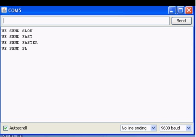
 This resource details the construction of a versatile CW/QRSS beacon, designed around a Microchip _PIC16F84_ microcontroller. The project provides a flexible platform for transmitting either standard CW or very slow QRSS signals, making it suitable for LF, VHF, UHF, and SHF applications. It supports two distinct messages, each configurable for speed (from 0 to **127** WPM for CW, or up to **127** seconds per dot for QRSS) and repetition within a six-phase sequence. The core functionality relies on the PIC's EEPROM, which stores all operational parameters, including message content, transmission speeds, phase configurations, and relay control settings. This design allows for parameter modification directly via programming software like _ICProg_ without altering the main program code. The project includes a detailed schematic, a component list, and an explanation of the EEPROM memory mapping for messages, speeds, phase settings, and inter-phase delays. General-purpose outputs (OUT1, OUT2, OUT3) provide dry relay contacts for external control, enabling functions such as power switching, antenna selection, or frequency changes. A 'TRIGGER' input facilitates controlled starts or continuous free-run operation. Sample EEPROM configurations illustrate how to program specific beacon sequences, including message content and relay states.
 -
 For amateur radio operators engaged in **radio direction finding** (RDF) and **transmitter hunting** (T-hunting) activities, this resource provides a catalog of printed circuit boards (PCBs) for constructing various DF and foxhunt-related projects. The offerings include PCBs for 80-meter fox transmitters and receivers, UHF fox transmitters with audio recording capabilities, and several designs for general-purpose radio direction finders. Specific projects like the "Simple 80M ATX-80 Transmitter" and the "N0GSG DSP Radio Direction Finder" are listed, along with attenuator boxes and specialized components for Doppler DF systems. The catalog details PCBs for projects published in prominent amateur radio magazines such as *73's*, *CQ*, *QST*, and *PE*, indicating their origin and design pedigree. For instance, the "Montreal Fox Controller" is sourced from the *Homing-In* column by Joe Moell, K0OV. The resource also lists components for advanced Doppler DF systems, including main boards, LED display boards, and antenna switch boards, with options for programmed PIC microcontrollers. Pricing for each PCB is provided, allowing hams to acquire the necessary components for their DIY RDF endeavors.
 -
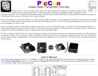 Hidden transmitter hunting, often called fox hunting or Amateur Radio Direction Finding (_ARDF_), presents a unique challenge for radio amateurs. This resource details the _PicCon_ controller, a specialized device designed to automate the transmission of signals for such events. It integrates with a standard radio transceiver, functioning similarly to a packet radio TNC, by controlling the Push-To-Talk (PTT) line and injecting audio tones or modulated CW Morse code into the microphone input. The _PicCon_ unit is field-programmable using DTMF tones received via the radio, storing all settings in EEPROM for power-off retention. Its compact design and low power consumption (a few milliamps from a 7-35VDC source) make it suitable for remote deployment. An onboard LED indicates operational status, and a push-button allows manual start/stop of transmissions without DTMF. Typically supplied as a kit, _PicCon_ includes a PCB, components, and a comprehensive manual (available in HTML, RTF, and PDF formats). The kit provides a six-conductor interface cable, but users must supply radio and power plugs due to varied configurations. Byon, _N6BG_, developed this controller, which is available from the Byonics website.
 -
 The MEL PICBASIC Forum serves as a community hub for users of Micro Engineering Labs PICBASIC compilers, facilitating discussions related to PIC microcontroller programming. It features dedicated sections for various compiler versions, including mel PIC BASIC, mel PIC BASIC Pro, and PBP3, each containing numerous threads and posts detailing specific programming challenges and solutions. The forum also provides areas for frequently asked questions, general PIC BASIC discussions, and commercial assistance requests. Specific sub-forums address advanced topics such as PBP Extensions, Code Examples, and AI and PICBASIC, offering insights into extending compiler functionality and integrating artificial intelligence concepts. Furthermore, the platform includes sections for Data Communications, covering USB, I2C, 1-Wire, GSM, and serial communications, which are critical for interfacing PIC microcontrollers with external devices. A dedicated area for PIC Programmers allows for discussions on programming hardware and techniques. The forum's utility is enhanced by its extensive archives of user-contributed solutions and examples, which can assist hams in developing microcontroller-based projects for radio applications. The platform's structure supports knowledge exchange among hobbyists and professionals working with PIC microcontrollers.
 -
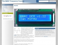 Accurate frequency measurement is crucial for amateur radio operators, particularly when building or troubleshooting transceivers and test equipment. This resource details the construction of a _PIC microcontroller_-based frequency counter, providing a practical solution for precise frequency display. The design incorporates an LCD readout, offering clear visual feedback of measured frequencies. The counter can operate as a standalone unit, useful for general bench testing, or be integrated directly into a receiver. Its built-in offset functionality allows for seamless integration, enabling the display of the received signal frequency rather than the intermediate frequency. The project focuses on accessible components and construction techniques, making it suitable for homebrew enthusiasts. Key features include a measurement range up to **50 MHz** and a compact form factor.
 -
 A 200 kHz bandwidth digital transmission system for image transfer in the Amateur Service is under development, specifically targeting VHF allocations. John B. Stephensen, KD6OZH, leads this project under an FCC Special Temporary Authority (STA) valid until September 10, 2006, authorizing emissions up to 200 kHz bandwidth in the 50.3-50.8 MHz segment. Current regulations typically limit bandwidths to 20 kHz on VHF amateur bands, making this STA crucial for testing wideband digital modes. The modem, a modified **OFDM** (Orthogonal Frequency Division Multiplexed) unit, was initially tested on the 70-cm band. It splits a high-rate data stream into multiple low-rate subcarriers to mitigate multipath echoes. The system uses a DCP-1 card with a Xilinx XC3S400 FPGA and Oki Semiconductor ML67Q5003 microcontroller. The transmitter, located at 36d 46m 30s N, 119d 46m 22s W, generates 150 WPEP into an 8 dBi gain vertical antenna, while the mobile receiver uses a Ham-stick. Three data formats for 50, 100, and 200 kHz channels are being tested, with encoded data rates of 96, 192, and 384 kbps. Verilog code for the VHF OFDM modem is 95% simulated, with modifications from the UHF version including increased filter coefficient precision and a change from Ungerboeck **TCM** to BICM for improved performance over fading paths. Final tests will involve one-way over-the-air measurements of bit error rates and coverage area.
 -
 The M0KGK keyer with variable speed and weight controls utilising a low cost PIC microcontroller.
 -
 Amateur Radio 40m 20m 15m Half Wave Fan dipole antenna project with part list, pictures and drawing. Includes the option to expand the antenna to cover the 80 meters band
 -
 The m0xpd keyer project utilizes a PIC16F628A microcontroller, offering Iambic A and B modes, adjustable speed from 5 to 40 WPM, and variable weight control. It incorporates a sidetone generator with adjustable frequency and volume, along with a PTT output for transceiver control. The design includes a 16-pin DIL IC socket for the PIC, a 3.5mm stereo jack for the paddle, and a 3.5mm mono jack for the PTT output. Powering the keyer requires a 9V DC supply, which is regulated down to 5V for the PIC. The circuit board layout is designed for through-hole components, facilitating home construction. A detailed schematic and a parts list are provided, guiding builders through the assembly process. The project also discusses the firmware programming for the PIC16F628A, essential for the keyer's functionality. Construction details cover component placement and wiring, ensuring proper operation. The keyer's compact size makes it suitable for portable or shack use, providing a reliable CW interface.
 -
 Sixty-meter repeaters typically use a 1 MHz frequency separation between input and output, while 2-meter repeaters commonly employ a **600 kHz** split and 70-centimeter repeaters use a **5 MHz** offset. This article details the fundamental technical principles of amateur voice repeaters, explaining how they extend VHF/UHF communication range by receiving on one frequency and simultaneously retransmitting on another. It covers essential components such as receivers, transmitters, filters, and antennas, often situated on elevated locations for optimal coverage. The resource delves into the critical challenge of _desensing_—where the repeater's strong transmit signal overpowers its own receiver—and the engineering solutions employed, including antenna separation and the use of high-Q cavity filters. It also explores various control and timing systems, from basic squelch activation to more sophisticated microcontroller-based boards that manage functions like voice identification, time-out timers, and fault protection. Different access methods are discussed, including open access, toneburst, CTCSS subtone, and DTMF, each offering distinct advantages for managing repeater usage and mitigating interference. Furthermore, the article examines repeater linking, both conventional RF methods and modern internet-based solutions, highlighting how linking expands coverage and promotes activity across multiple repeaters or bands. It introduces less common repeater types such as 'parrot' repeaters, which use a single frequency and digital voice recording, and linear translators, capable of relaying multiple signals and modes simultaneously across different bands, often found in amateur satellites.
 -
 Low-frequency (LF) radio time signals, operating primarily in the 40–80 kHz range, are broadcast by national physics laboratories for precise clock synchronization. Transmitters like **JJY** (40 kHz, 50 kW; 60 kHz, 50 kW), RTZ (50 kHz, 10 kW ERP), MSF (60 kHz, 15 kW ERP), WWVB (60 kHz, 50 kW ERP), RBU (66.66 kHz, 10 kW), and DCF77 (77.5 kHz, 50 kW) cover vast geographic areas, often several hundred to thousands of kilometers. LF signals offer distinct propagation advantages over higher-band transmissions such as GPS. Their long wavelengths (3–6 km) enable effective diffraction around obstacles like mountains and buildings. The ionosphere and ground act as a waveguide, eliminating the need for line-of-sight and allowing a single powerful station to cover extensive regions. Ground wave propagation minimizes ionospheric variability effects on transmission delay, and signals penetrate most building walls effectively. Robust and low-cost receivers, often priced at 20–30 USD/EUR, are widely used in radio clocks. These receivers typically comprise a tuned ferrite core antenna, a receiver IC (e.g., Atmel T4227, U4223B, MAS1016) for amplification and AM detection, and a microcontroller for decoding the time signal and phase-locking a local clock. Specific components for DCF77, MSF, and WWVB are readily available from vendors like HKW Elektronik and Ultralink.
 -
 CW decoder using a PIC microcontroller. This is a morse code decoder made using a PIC(16F88) microcontroller, this project supports displays with multiple controller chips
 -
 A data converter for the Tandy WM918 weather station. The Weather APRS data converter project aims to create an interface to interpret data from the popular Tandy WM918 weather station and format it for transmission over packet radio. The South East Radio Group in South Australia has established a network of these weather stations to provide amateurs with regularly updated weather data. However, the WM918's data output is not structured for APRS weather reporting. This project describes a solution using a PIC microcontroller to convert the WM918 data into APRS-compatible strings that can be sent as beacons or connected packets. The interface offers features like position/positionless data, connected/beacon modes, and metric/imperial units. The goal is to create an interconnected weather reporting system for amateur radio operators
 -
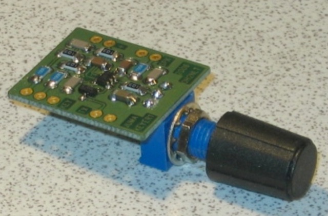 Miniature PIC microcontroller based keyer kit with convenient modes. The kit includes PCB, componets, knob and ready programmed PIC microcontroller. Author make available from his web site Circuit diagram, Component layout,List of components and downloadable Software
 -
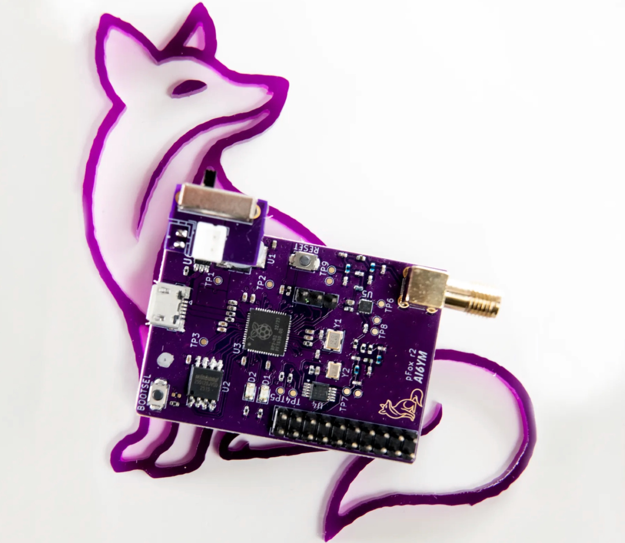 The PicoFox is a versatile fox transmitter for 2-meter ham radio operators, built around the RP2040 microcontroller. With open-source hardware and software, it can be customized to suit your needs, from APRS to other digital modes. This fully assembled transmitter comes with a rechargeable battery and antenna, ready for use. The design allows for easy addition of features like sensors or interactivity. Modulation is handled in software for smooth FM output, with ample CPU, flash, and GPIO available. Configure your PicoFox by connecting it to a computer via USB and adjusting settings in a text file. Explore the possibilities of this innovative transmitter for your amateur radio projects.
 -
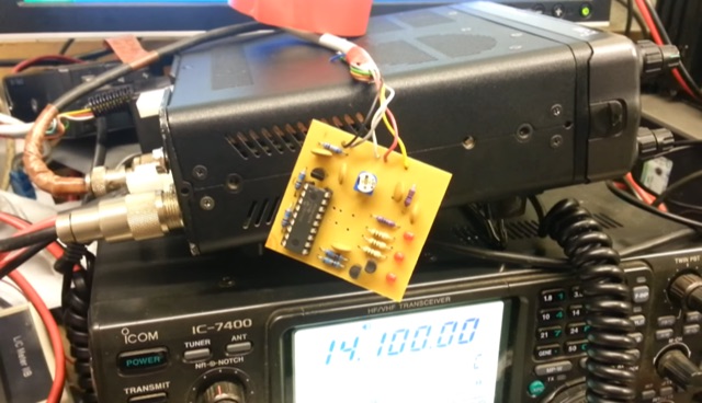 This project details an automatic roger beep circuit for VHF/UHF contests. Built around a Microchip PIC microcontroller, the design detects PTT (Push-To-Talk) activation and generates a brief tone upon release, mimicking a "roger beep" to signal the end of transmission. The circuit utilizes readily available components and includes downloadable resources for PCB layout and firmware.
 -
 This project outlines a simple Lead Acid/SLA battery monitor, designed to alert users when battery voltage falls below 10.6V. The monitor, based on a PIC16F1827 microcontroller, checks the voltage of up to five batteries and triggers an alarm if any drop too low. The system operates in various modes, including self-test, monitoring, and alarm. This updated version improves upon the original 1999 design, offering a more modern microcontroller and extended functionality for workshop use, with minimal impact on battery charge.
 -
 The project aims to create a remote control system for the VK5RSE beacons located near Millicent, South Australia. The beacons on 144.550, 432.550, and 1296.550 MHz can interfere with nearby amateur radio operations, particularly for EME work on 1296 MHz. The remote control system uses a DTMF decoder and PIC microcontroller to allow turning the beacons on and off individually or in combination. The system is housed in a diecast box and powered from 5-8V. The password-protected control allows authorized users to manage the beacon operations remotely, helping mitigate interference issues for local amateurs.
 -
 The W6PQL 23cm Beacon Project describes a **1296 MHz** beacon designed for microwave propagation studies and equipment testing, capable of 30 watts output. It utilizes a PIC 16F628A microcontroller to generate CW and FSK keying for a crystal oscillator, followed by a series of frequency doublers and triplers to reach the target frequency. The final power amplification stage employs a Mitsubishi M57762 module, providing a robust 10-watt RF output. The design emphasizes stability and reliability for continuous operation, with the microcontroller code, written in assembly, provided for customization of the beacon's callsign and message. Originally located in CM97am and aimed at 140 true, the beacon used four 4-foot Yagis stacked vertically for a total ERP of 3kW. The article includes schematics, parts lists, and construction notes to guide builders, along with antenna pattern measurements. Although the beacon itself is no longer in service as of August 2010, the detailed documentation remains a valuable reference for amateur radio operators interested in building similar **microwave** projects or understanding beacon operation.