Search results
Query: RF energy
Links: 18 | Categories: 0
-
 Sixty-four years of operating experience inform Glynn E. "Buck" Rogers Sr., K4ABT's, insights into the J-Pole antenna, which he describes as a direct descendant of the _Windom_ or _ZEPP_. His first article on the J-Pole appeared in HRC magazine in 1958, and he has since published numerous pieces in publications like CQ Magazine, consistently referring to the J-Pole as a Windom with a folded-back short section forming the parasitic element. He emphasizes that both the Windom and J-Pole are powerful multi-band antennas, performing exceptionally well at harmonics of their fundamental design frequency, and advocates for 50-ohm coaxial cable with a _BALUN_ at the feed-point to avoid RF energy losses. K4ABT details the J-Pole's features, noting its ease of erection, lack of radials, low angle radiation, greater bandwidth, and immunity to terrestrial noise. He highlights its suitability for local nets and distant repeaters, claiming more gain and durability than most ground planes, and its ability to meet stealth antenna requirements. The guide provides specific dimensions for 2-meter (145.000 to 146.000 MHz) and 6-meter (50.500 to 51.500 MHz) J-Pole antennas, including measurements for the long driven element, short tuning stub, and spacing. The construction section illustrates a modified feed technique using an SO-239 chassis-mount coax connector soldered into a copper tee, deviating from the usual hose clamp method. The author also discusses the use of _EMT_ (electrical metallic thin-wall conduit) as an alternative to copper in earlier days. He cautions against building a 75-meter J-Pole due to its impractical length, reinforcing the antenna's optimal application for VHF and UHF bands.
 -
 The article details antenna tuning procedures, emphasizing SWR measurement and adjustment for both mobile and base station setups. It explains that SWR (Standing Wave Ratio) is the ratio of transmitted power to reflected power, with high SWR indicating poor impedance match and potential damage to a transceiver's final amplifier. Specific instructions are provided for CB antennas operating between 26-27 MHz, recommending initial SWR checks on channels 1, 20, and 40 to determine if the whip needs shortening or lengthening. Adjustments should be made in small increments, approximately 1/4 inch at a time, aiming for an SWR of 1.5:1 or better. For _Ham radio_ and other antennas, the same tuning principles apply, with a strong caution regarding RF energy exposure when operating at higher power levels. The resource suggests tuning base antennas at ground or roof level before final installation to simplify adjustments. It also advises rechecking SWR after final installation to confirm no changes occurred. The _Alpha Rubicon_ resource highlights the importance of a good ground plane for mobile antennas and proper coax routing to avoid pinching or proximity to electrical wires.
 -
 An antenna does not have to be resonant to work, as the primary reason for resonance is to eliminate the need for an impedance-matching device. A non-resonant wire dipole fed with open-wire line and an antenna tuner can function as an effective multiband antenna. Two wires are essential for powering an antenna, ideally with a balanced configuration like a dipole fed by parallel-wire line, though coaxial cable can be used with a 1:1 balun to mitigate RF feedback on the shield. Antenna gain is achieved by shaping and aiming RF energy, concentrating it in a particular direction, as seen in beam antennas or shaped radiation patterns of wire antennas. The function of an antenna tuner is to match the transceiver's 50 Ohm output to the antenna system's impedance, which can vary widely. Wire antennas do not always require center feeding; end-fed long wires or off-center-fed dipoles (Windom antennas) can be used, often requiring a counterpoise or radial system. Dipole antennas do not need to be perfectly horizontal; their legs can be bent, inclined, or even vertical, affecting feed point impedance. Vertical antennas shorter than a half wavelength necessitate a ground system, typically comprising radial wires, with more radials generally leading to greater efficiency. A 1:1 SWR indicates an impedance match but does not guarantee a good antenna, as an inefficient antenna with a poor ground system can still show a perfect SWR while wasting RF as heat. Always using the best feed line affordable is crucial for minimizing loss and maximizing RF signal delivery to and from the antenna.
 -
 This resource details the four primary functions of a ground system: lightning energy dispersion, equipment safety, RF return path provision for end-fed antennas, and management of induced RF currents. It clarifies that a ground system's effectiveness varies depending on its specific function, noting that a good lightning ground might not be an effective RF ground. The content emphasizes that proper antenna system design, including baluns and appropriate feedline lengths, often negates the need for an RF station ground to mitigate common mode currents or RFI in the shack. The article quantifies lightning energy, stating its peak is in the dozens or hundreds of kilohertz, with damaging energy extending to hundreds of megahertz, and currents reaching thousands of amperes. It recommends solid, wide, smooth copper surfaces for ground leads to achieve low impedance across a wide frequency range. The author, W8JI, shares practical insights from his station, which includes two 300-ft towers and four 130-ft wire verticals, detailing his use of common point grounds and _DX Engineering RR-8 HD_ antenna switches for lightning protection without coaxial surge protectors. Specific examples of antenna systems prone to common mode current problems are listed, such as random wire antennas without proper feedline lengths and off-center fed dipoles. The text also explains how a ground screen or radial system can reduce local noise sensitivity for vertically polarized antennas by covering the lossy earth.
 -
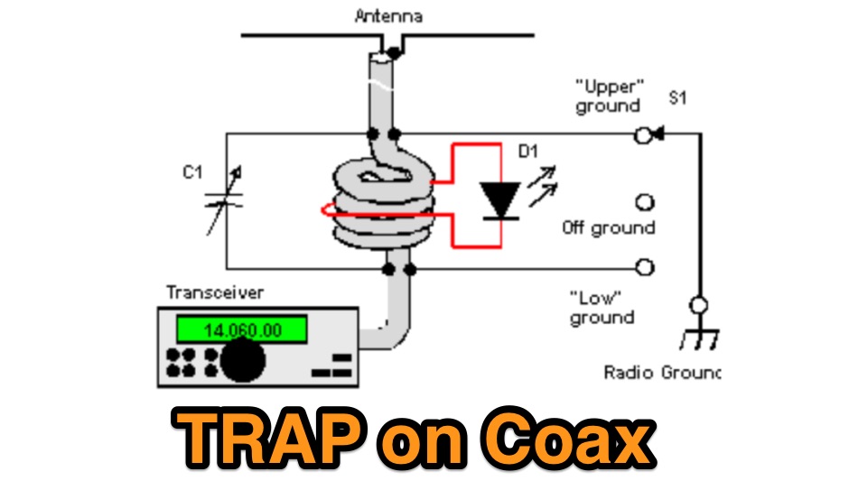 A trap on the coaxial cable, also known as choke, helps to eliminate the sneaking of the reflected RF- energy to the shack. The trap can be made from the coaxial cable that feeds the antenna
 -
 Protecting amateur radio equipment from transient overvoltages requires robust lightning and surge protection, which is the focus of Electronic Specialty Products. The company provides various devices, including coaxial lightning arrestors for antenna feedlines and surge protectors for AC power lines and data circuits. These devices are engineered to divert high-energy surges, such as those caused by direct or indirect lightning strikes, away from sensitive transceivers, amplifiers, and computer components, thereby preventing catastrophic damage. Key products include the _Coaxial Lightning Protector_ series, designed for various impedance levels and frequency ranges up to 3 GHz, and the _AC Line Surge Protector_ for shack power distribution. Effective deployment of these protection devices can significantly reduce the risk of equipment failure and ensure operational continuity during severe weather. For instance, a properly installed coaxial arrestor can handle peak currents of **20 kA**, while AC line protectors offer clamping voltages typically below 400V. Comparing different models reveals varying levels of insertion loss and return loss, with some coaxial units exhibiting less than 0.1 dB loss at 500 MHz, making them suitable for high-performance HF and VHF/UHF operations. Integrating these components into a comprehensive grounding system is crucial for achieving maximum protection against both common-mode and differential-mode surges.
 -
 Ten essential tips and truisms for understanding HF antenna: Non-resonant wire dipole antennas fed with open-wire line and an antenna tuner can function effectively as multiband antennas, as detailed in "The Classic Multiband Dipole Antenna" by WB8IMY in March 2004 QST. Coaxial cable, unlike balanced parallel-wire feed lines, can cause RF to travel on the outer shield braid, leading to RF feedback to the station; a 1:1 balun at the dipole center can mitigate this by isolating the unbalanced coaxial feed line. Antenna gain is achieved by shaping and directing RF energy, with beam antennas concentrating power in a specific direction, and wire antennas also exhibiting shaped radiation patterns. An antenna tuner's primary role is to match the transceiver's 50-ohm output to the antenna system's impedance, allowing modern transceivers to deliver full power. Wire antennas do not always require center feeding; end-fed long wires or off-center-fed dipoles (like the Windom) can be used, though they often necessitate an antenna tuner and a counterpoise or radial network. Dipole antennas do not need to be perfectly horizontal; their legs can be bent or inclined, which affects feed point impedance and may require SWR experimentation with coaxial feed. Vertical antennas shorter than a half wavelength require an efficient ground system, typically comprising elevated or buried radial wires, with more radials generally leading to better efficiency. A 1:1 SWR indicates an impedance match but does not guarantee antenna efficiency; an inefficient vertical antenna with a poor ground system can show a low SWR while wasting most RF as heat. Investing in high-quality, low-loss feed line, especially coaxial cable, is crucial for maximizing RF signal transfer and overall antenna system performance.
 -
 TSC International produces soft magnetic sheet steel, custom-stamped and heat-treated to achieve optimal electrical characteristics for applications such as motors, generators, linear power supplies, and ballasts. The company's manufacturing process focuses on precise material engineering to meet specific performance requirements in various electrical systems. They also specialize in soft magnetic core materials essential for transformers, chokes, and inductors. These core materials are utilized in power supplies, lighting ballasts, signal conditioning circuits, inverters, and battery chargers, providing critical magnetic properties for efficient energy conversion and signal integrity. Located at 39105 Magnetics Blvd, Wadsworth, IL 60083-0399, TSC International provides contact via sales@tscinternational.com or phone at +1 (0) 847 249 4900, facilitating direct inquiries regarding their magnetic component offerings.
 -
 An Energy Analysis at an Impedance Discontinuity in an RF Transmission Line
 -
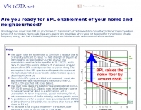 Broadband over power lines (BPL) is a technique for transmission of high speed data (broadband Internet) over powerlines. Access BPL technology injects radio frequency energy into powerlines which were not designed for transmission of radio frequency energy, and leak substantial energy that causes interference to radiocommunications service
 -
 A 2m band Moxon antenna design is presented, centered at 145.2 MHz, with dimensions derived from Moxgen software. The design features a calculated 6 dBi gain, an 80-degree beamwidth, and an impressive 43 dB front-to-back ratio with minimal back lobes, concentrating RF energy in the forward direction. The antenna is balanced to 50 Ohms, facilitating direct feed. SWR sweep data from 144 MHz to 146 MHz demonstrates a near 1:1 SWR at the center frequency, maintaining healthy SWR values across the entire 2m amateur band. This performance is comparable to a 3-element Yagi, yet the Moxon offers advantages in compact size and ease of mast mounting, making it suitable for various operating environments.
 -
 Operating where independent media is suppressed, _Radio Free Europe/Radio Liberty_ (RFE/RL) delivers news and information in 27 languages to audiences in 23 countries. This resource primarily functions as a news portal, focusing on geopolitical events, regional conflicts, and human rights issues, particularly in areas like Ukraine, Russia, Iran, Afghanistan, and Central Asia. It features articles, videos, podcasts, and photo galleries, covering topics such as international relations, energy politics, and the impact of conflict on civilian populations, often highlighting the perspectives of local journalists and freelancers in challenging environments. The content frequently addresses the operational context of shortwave broadcasting, though the site itself is a digital news platform. For example, it details the implications of long-distance strikes and regional military capabilities, which are relevant to understanding the strategic importance of various communication methods. The resource also provides insights into the challenges faced by populations in areas with limited access to uncensored information, underscoring the role of independent news organizations in providing alternative narratives.
 -
 GoGreenSolar provides comprehensive solutions for **DIY solar panel systems**, catering to both homeowners and professionals seeking energy independence or reduced utility costs. Their offerings include a variety of solar kits such as Grid-Tie, Off-Grid, and Battery Backup configurations, designed to integrate seamlessly with existing utility infrastructure or provide complete autonomy in remote locations. Customers can select from Microinverter or String Inverter kits, along with essential components like **solar panels**, inverters, batteries, and racking systems, all curated from reputable brands known for efficiency and durability. The company emphasizes end-to-end support, from initial consultation and custom system design to providing easy-to-follow installation manuals. They offer financing options, including quick-approval loans with zero down payment, and a money-back guarantee if a solar permit is not approved. The platform also features a solar calculator and a questionnaire to help users determine the most suitable system for their specific energy requirements and property characteristics. GoGreenSolar aims to simplify the solar adoption process, enabling significant savings on energy bills and labor costs. Their approach focuses on empowering users to install their own systems with expert guidance, ensuring optimal performance and a secure energy future for homes and businesses.
 -
 Preprinted from the 1997 ARRL Handbook for Radio Amateurs. Thermal Effects of RF Energy, Safe Exposure Levels, Cardiac Pacemakers and RF Safety, Determining RF Power Density
 -
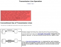 The resource, "Conventional Use of Transmission Line," meticulously details the operational principles of transmission lines, emphasizing the Transverse Electromagnetic (TEM) mode of energy transfer. It clarifies that for a line to function purely as a transmission line, all currents must be confined internally, with external fields ideally zero. The discussion differentiates between balanced and unbalanced lines, asserting that while both require equal and opposite currents within the conductors, the key distinction lies in the voltage relationship of each conductor to the surrounding environment. It highlights that a good antenna pattern does not inherently confirm proper feeder balance, and that common-mode currents can lead to RF in the shack and increased noise levels, even without pattern distortion. The article further explains that a transmission line can become a radiating conductor if energy is applied in a non-TEM mode, leading to common-mode issues. It cites classic texts like Jordan and Balmain's "_Electromagnetic Waves and Radiating Systems_" and Kraus's "_Antennas_" to support its definitions of TEM mode operation. The content also explores non-transmission line applications of parallel or concentric conductors, such as _coaxial dipoles_ and _folded dipoles_, which intentionally operate in non-TEM modes for antenna functionality. The author, _W8JI_, stresses that simply measuring equal currents is insufficient to confirm a balanced feeder; phase and voltage balance to ground are equally critical.
 -
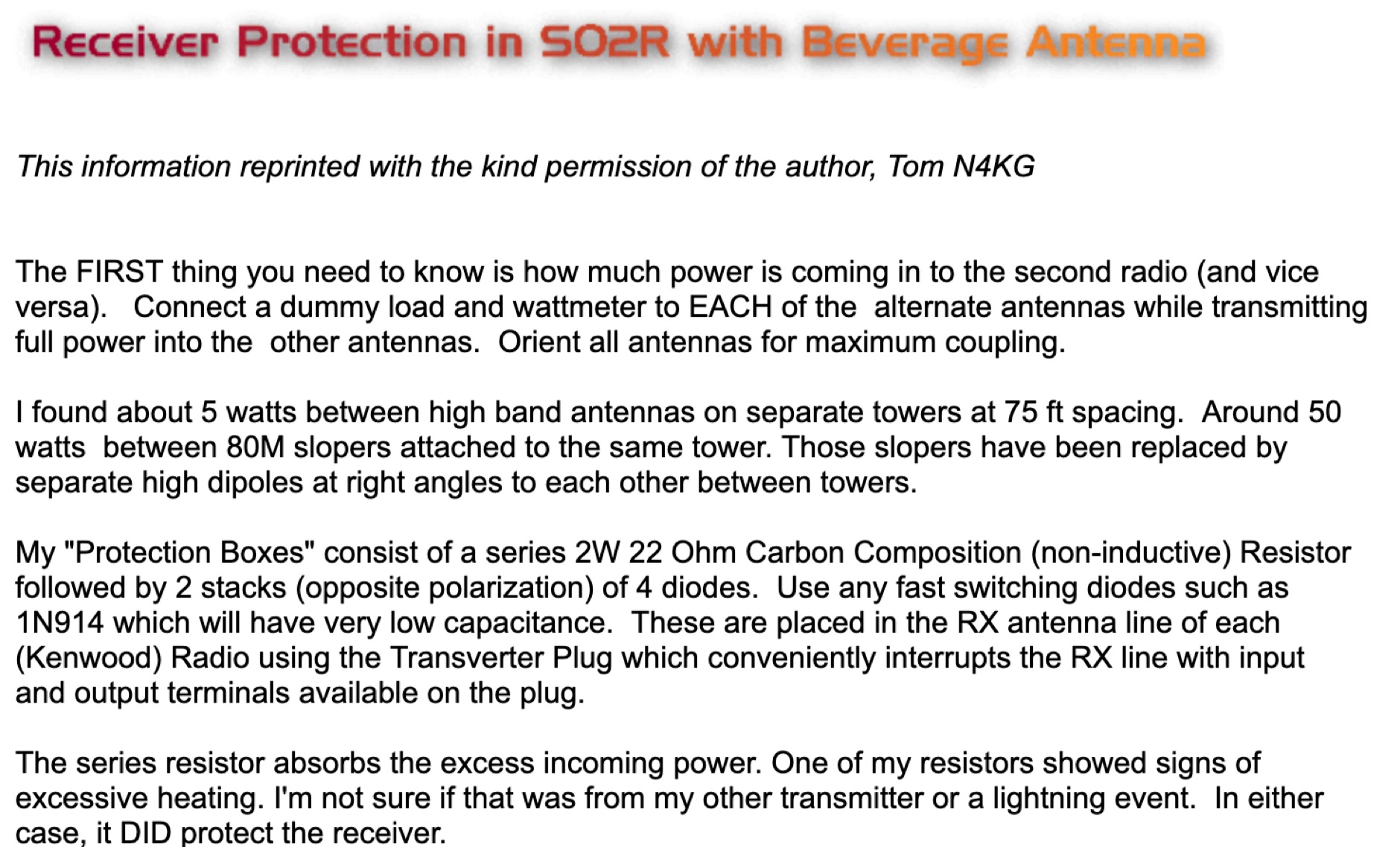 Operating in a Single Operator Two Radios (SO2R) setup, especially with beverage antennas, often exposes the receiving radio's front-end to significant RF energy from the transmitting radio. This resource details a practical, homebrew receiver protection circuit designed to mitigate this risk. The core of the design involves a non-inductive 2W 22 Ohm carbon composition resistor in series with the RX antenna line, followed by two stacks of four fast-switching diodes (e.g., _1N914_) configured in opposite polarizations. This arrangement effectively clamps the incoming voltage to approximately 2.8 V peak-to-peak, safeguarding sensitive receiver input components. The series resistor plays a crucial role by absorbing excess power, preventing the diodes from exceeding their current ratings and potentially failing open, which would leave the receiver unprotected. The author, _N4KG_, measured up to 50 watts of coupled power between 80M slopers on the same tower, highlighting the necessity of such protection. The design is presented as a cost-effective solution to prevent damage to receiver input transformers, with the author noting successful protection of a receiver even after a resistor showed signs of overheating. This simple circuit can be integrated via a transverter plug, offering a robust defense against high RF input.
 -
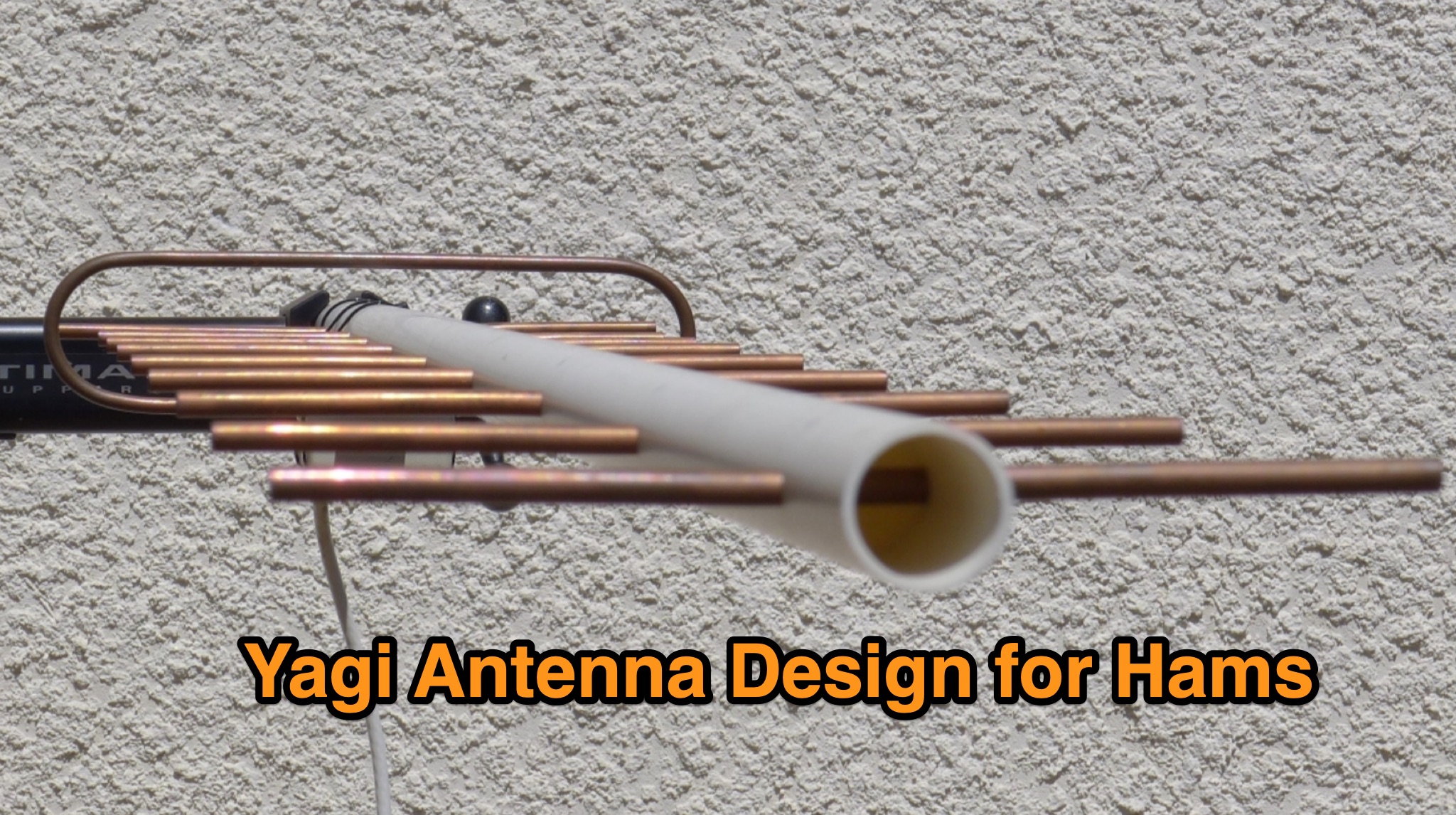 Learn about the practical design and construction of Yagi antennas for ham radio operators. This post explores the benefits of Yagi antennas in receiving and transmitting RF signals, concentrating signal energy in one direction for long-distance communication. Discover the theory behind Yagi antennae, the importance of element size and spacing, and the resources available for sizing and construction. Whether you're interested in OTA television or amateur radio communication, understanding Yagi antenna design can enhance your signal reception and transmission capabilities.
 -
 Mounting on roof at the right ground level can greately impact on antenna performances because will affect the radiated angle of energy.