Search results
Query: US BAND PLAN
Links: 111 | Categories: 12
-
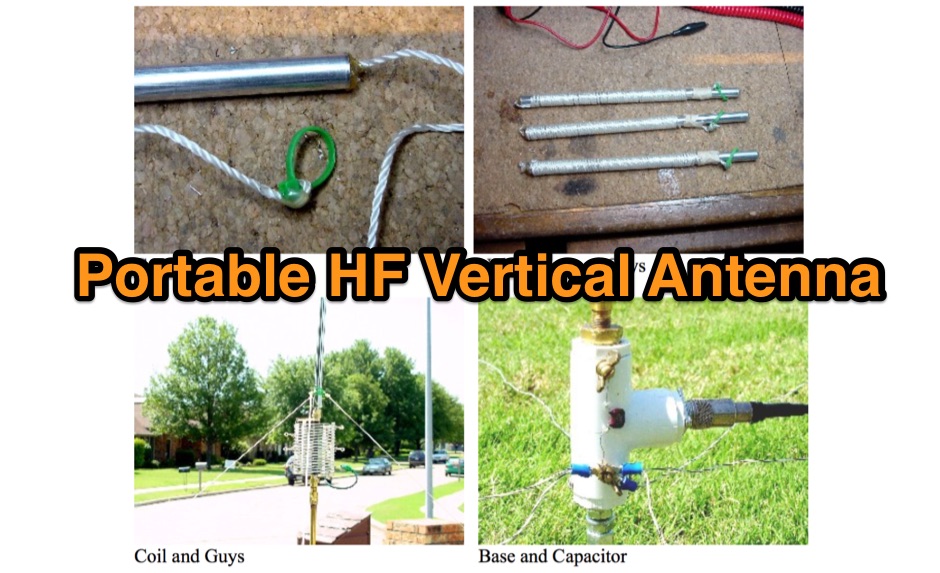 Homemade 40 through 6 meter HF portable multiband antenna, an aluminium antenna construction article, with plan, drawings and photos
 -
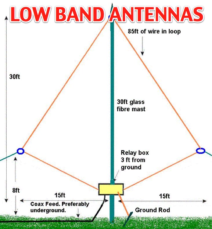 The page provides detailed plans and pictures of 80m and 160m antennas for both transmission and reception, emphasizing the importance of antenna farm on low bands. It discusses the differences between TX and RX antennas, the significance of signal-to-noise ratio, and the benefits of directional antennae. The author shares personal experiences and recommendations for successful operation on low bands.
 -
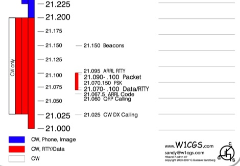 Free downloadable band plans layouts ready to print in pdf format by C.Gustave Sandberg W1CGS, band plans are updated to 2007.
 -
 Sixty-four years of operating experience inform Glynn E. "Buck" Rogers Sr., K4ABT's, insights into the J-Pole antenna, which he describes as a direct descendant of the _Windom_ or _ZEPP_. His first article on the J-Pole appeared in HRC magazine in 1958, and he has since published numerous pieces in publications like CQ Magazine, consistently referring to the J-Pole as a Windom with a folded-back short section forming the parasitic element. He emphasizes that both the Windom and J-Pole are powerful multi-band antennas, performing exceptionally well at harmonics of their fundamental design frequency, and advocates for 50-ohm coaxial cable with a _BALUN_ at the feed-point to avoid RF energy losses. K4ABT details the J-Pole's features, noting its ease of erection, lack of radials, low angle radiation, greater bandwidth, and immunity to terrestrial noise. He highlights its suitability for local nets and distant repeaters, claiming more gain and durability than most ground planes, and its ability to meet stealth antenna requirements. The guide provides specific dimensions for 2-meter (145.000 to 146.000 MHz) and 6-meter (50.500 to 51.500 MHz) J-Pole antennas, including measurements for the long driven element, short tuning stub, and spacing. The construction section illustrates a modified feed technique using an SO-239 chassis-mount coax connector soldered into a copper tee, deviating from the usual hose clamp method. The author also discusses the use of _EMT_ (electrical metallic thin-wall conduit) as an alternative to copper in earlier days. He cautions against building a 75-meter J-Pole due to its impractical length, reinforcing the antenna's optimal application for VHF and UHF bands.
 -
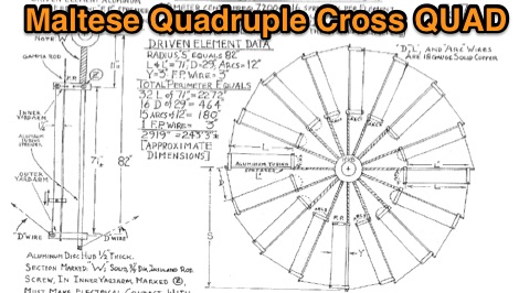 The Pfeiffer Maltese Quad Antenna System presents a unique approach to traditional quad antennas by utilizing a linear loading technique. This method effectively reduces the overall size of the antenna while maintaining its performance capabilities. Designed by Andrew Pfeiffer, the antenna's configuration resembles a Maltese cross, which not only enhances its structural integrity but also allows it to withstand challenging environmental conditions. This system is adaptable, offering various configurations from a 4-spreader Maltese Quad to a 16-spreader Maltese Quadruple-Cross, making it suitable for operators looking to optimize their setup without sacrificing efficiency. This antenna system is particularly versatile, covering multiple bands including 40, 20, 17, 12, and 10 meters. The design focuses on minimizing the physical footprint while ensuring effective signal transmission and reception. Amateur radio operators can benefit from the detailed plans available in the accompanying PDF, which outlines the construction process and specifications. Whether you're a seasoned DXer or a newcomer to the hobby, the Pfeiffer Maltese Quad Antenna System offers a practical solution for enhancing your station's capabilities.
 -
 A 1/4 wavelength resonator design for dual-band VHF/UHF operation is presented, focusing on a robust mobile antenna construction. The design prioritizes stability against environmental influences over raw gain, making it suitable for general use rather than marginal signal areas. It details the antenna's two sections: a UHF-resonant lower conductor and an upper coil functioning as an RF choke for UHF and an inductance enhancer for VHF, forming a resonant circuit. Detailed mechanical structure and material considerations are provided, including the use of a PL-259 plug base, 2mm copper rod, and PVC faucet tube for the coil form. The guide outlines a precise construction procedure, from soldering the copper rod to the PL-259 to winding the 22 SWG laminated wire for the VHF section. Tuning involves careful cutting of the UHF section and adjusting the coil length and pitch for VHF, using a reflectometer and temporary ground planes. Furthermore, the resource describes converting the mobile antenna for base station application by constructing a dual-band ground plane system. This involves using electrical conduit, EMT connectors, SO-239 sockets, and a 4-inch round-pan with threaded stainless steel rods as ground elements. Practical test results indicate optimal lengths of **70mm** for UHF and **350mm** for VHF ground elements, with a recommendation to cut rods with _30mm_ extra length for fine-tuning.
 -
 This resource presents the _FCC_ Online Table of Frequency Allocations, codified under 47 C.F.R. § 2.106. The document details frequency assignments across the electromagnetic spectrum, from 0 kHz to beyond 2170 MHz, specifying allocations for various radio services including amateur, maritime mobile, aeronautical radionavigation, and broadcasting. The table is structured with columns for International Table (ITU Radio Regulations Article 5, Section IV, 2019 Edition), United States Table (Federal and Non-Federal), and corresponding _FCC_ Rule Part(s). Specific frequency ranges, such as **135.7-137.8 kHz** and **472-479 kHz**, are identified with their primary and secondary allocations, including Amateur Radio (Part 97) and Maritime Mobile (Part 80). The methodology involves direct publication of regulatory data, reflecting amendments adopted by the _FCC_ that may not yet be codified in the Code of Federal Regulations. Each entry provides the allocated service (e.g., METEOROLOGICAL AIDS, RADIONAVIGATION), relevant footnotes (e.g., 5.53, US18), and the applicable _FCC_ Rule Part. For example, the 1800-2000 kHz range is allocated to AMATEUR radio under Part 97, alongside MOBILE services. Contact information for the Office of Engineering and Technology Policy and Rules Division is provided for inquiries regarding the data. DXZone Focus: Regulatory Database | FCC Publication | Frequency Allocation | Rule Part Reference
 -
 Over 16.7 million callsigns are indexed within the HamCall World-Wide Callsign Database, a long-standing resource for amateur radio operators. This online tool facilitates rapid lookups of callsign data, including operator details and QSL photos, which are crucial for confirming contacts and pursuing operating awards. The database integrates FCC updates as they are released, ensuring timely access to current licensing information. The platform also features a live **DX cluster** displaying recent spots across various bands, from 160m to 3cm, with specific spot counts for active bands like 15m (50 spots) and 10m (46 spots). Users can view **band activity** summaries, providing an immediate overview of propagation conditions and active frequencies. Additionally, the service provides access to a hamfest calendar and amateur radio news updates, making it a multi-faceted resource for daily operating and event planning. Since 1989, the HamCall DVD has supported this server, alongside HamCall.net Gold Memberships, demonstrating a sustained commitment to providing comprehensive callsign data.
 -
 The ARRL website provides a graphical representation of US frequency allocations for amateur radio operators. Users can download a PDF document containing the band plan and access additional information on frequency bands and regulatory aspects.
 -
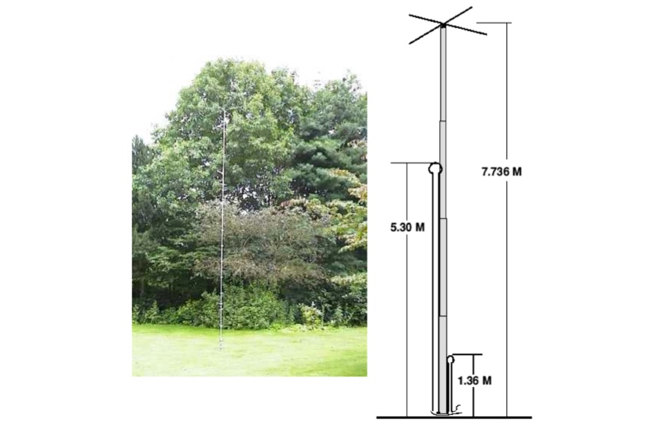 This Vertical antenna design by David Reid for lower bands focuses on achieving effective DX communication by optimizing the antenna low-angle radiation for long-distance contacts. The design incorporates techniques like linear loading and capacity hats to reduce the antenna's height while maintaining performance, especially on 40m and 80m bands. Building a solid ground plane and using quality materials ensure efficiency and durability. Although vertical antennas can be complex to build, this project simplifies the process, making it accessible for ham operators seeking strong, reliable signals.
 -
 Details the construction and optimization of antenna systems for amateur radio satellite operations, focusing on practical, homebrew solutions for VHF/UHF bands. It covers building _groundplane antennas_ from salvaged materials, recycling old beam antennas into new configurations like a 2-meter crossed yagi, and constructing a 10-meter horizontal delta loop. The resource also explains antenna matching techniques, including folded dipole driven elements and quarter-wave transformers, along with the importance of accurate SWR measurements and minimizing coax loss. Demonstrates how to achieve a **1:1 SWR** by carefully trimming elements and adjusting radial angles on groundplane antennas. It provides insights into selecting appropriate coax and connectors, highlighting the benefits of Belden 9913 for low loss and the proper installation of _N-connectors_. The article also addresses RFI mitigation from computer birdies and presents a design for a silent triac antenna control circuit, offering practical solutions for common satellite station challenges.
 -
 Presents detailed plans and construction notes for a compact 3-element Yagi antenna specifically designed for the 50 MHz band, authored by Ken Willis, _G8VR_. The article, originally published in _Practical Wireless_ in 1989 and updated in 1999, outlines the design philosophy behind a small, gain-oriented antenna suitable for restricted QTHs. It covers element dimensions, boom length, and a unique coaxial _gamma match_ system, emphasizing a "plumber's delight" construction approach using readily available hardware. The resource details the author's operational experience, achieving _DXCC_ on 50 MHz with over 110 countries worked using this antenna. It also incorporates insights from computer simulation studies by _G3SEK_ and _W1XP_ using _MININEC_, which suggested minor adjustments to element lengths and spacing for improved front-to-back ratio, increasing it from 14dB to 31dB. The author compares theoretical performance with practical results, noting that while larger arrays might offer a few dB more gain, this compact design provides excellent performance for F2 propagation and general 6-meter DXing.
 -

-
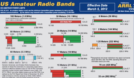 Download this color US ham radio band-plan in PDF format edited by ARRL
 -
 SM0DTK's 40-meter Moxon antenna project details the construction and deployment of a wire Moxon rectangle, specifically dimensioned for the 7 MHz band. The resource outlines the use of a _Moxon Rectangle Generator_ for calculating wire lengths and the fabrication of plexiglass supports for corners and the feeding point. It describes the practical challenges of elevating the antenna to approximately **14 meters** using an aluminum tube and fiberglass rod, emphasizing the adjustment process for achieving the correct rectangular shape. The article presents comparative results against a 60-meter long-wire and a full-size 40-meter ground plane antenna. The Moxon demonstrated significant directional gain towards the west, facilitating DX contacts in the Caribbean with **100 watts**, while simultaneously reducing QRM from strong eastern European stations. The SWR was reported as perfect without the need for an antenna tuner, validating the design's effectiveness for targeted signal enhancement and interference mitigation.
 -
 For amateur radio operators seeking a compact, directional antenna for the 10-meter band, this resource details the construction of a Moxon Yagi beam. The design utilizes readily available PVC pipe for the boom and elements, with specific measurements derived from the Moxon Rectangle Generator software. It outlines the assembly process for the main boom and end sections, providing critical dimensions for element spacing and overall length to achieve resonance at 28 MHz. The Moxon configuration offers a smaller footprint compared to a traditional Yagi, making it suitable for limited space installations. The article provides practical guidance for hams interested in a DIY antenna project, emphasizing the use of common hardware store materials. It specifies a 1 1/4" PVC schedule 40 pipe for the main boom and details the use of tees, reducing bushings, and 45-degree elbows for the element ends. Key measurements like the 55" spacing for the ends and the 150 3/4" overall length are provided, enabling replication of the design. The Moxon's inherent wide beamwidth and good front-to-back ratio make it an effective choice for DXing on 10 meters.
 -
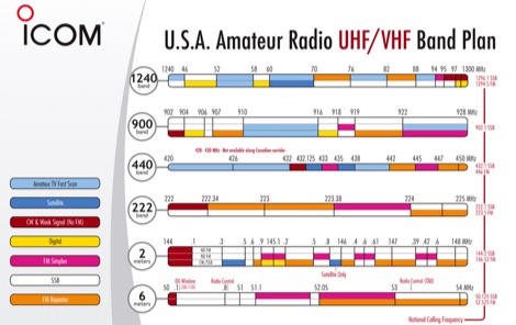 Download the PDF with USA Amateur radio HF band plan and common country prefixes updated in 2008 by Icom
 -
 US ham radio band plan in pdf available for download and print
 -
 Automatic Link Establishment (ALE) is a digital signaling protocol enabling HF radio stations to automatically establish communication links, crucial for emergency and disaster relief operations. HFLINK serves as a central international resource for ALE High Frequency Communications, HF Selective Calling (SELCALL), and general HF interoperability. The platform provides extensive information on ALE operation, including frequency networks, band plans, and software like _PCALE_ for amateur radio integration. It also documents significant events such as the _HF Interoperability Exercise (HFIE)_ and the _Global Simulated Emergency Test (GlobalSET)_, which allow ham operators to gain real-world experience in interoperable HF communications, often using specific frequencies like the USA 5 MHz ALE simplex frequency 5371.5 kHz USB. The site features articles on antenna types popular among ALE users, such as autotuners and broadband antennas like the _T2FD_ and the Broadband Butterfly Terminated Dipole (BBTD).
 -
 Constructing an HF End-Fed Half-Wave (EFHW) vertical antenna, the resource details the winding of a monoband matching unit, inspired by _AA5TB_, designed to provide a 50 Ohm impedance match without a ground plane or antenna tuner. It specifies the use of a _T200-2_ ferrite core for the transformer, outlining the 13-turn secondary and 2-turn primary winding process with enamelled copper wire. The document also describes the integration of a coax capacitor, whose length is critical for tuning and varies by band, with specific starting lengths provided for 20m, 17m, 15m, 12m, and 10m operation. The practical application section guides the builder through tuning the antenna using an antenna analyzer, emphasizing the iterative process of spacing secondary windings and trimming the coax capacitor to achieve resonance at the desired band frequency. It highlights the antenna's low angle of radiation, beneficial for DX, and claims up to 2 S-points improvement over a _G5RV_ or similar doublet when used as an omnidirectional vertical. A comprehensive shopping list, including specific part numbers from _Rapid Electronics_, is provided, along with advice on selecting fiberglass fishing poles for support and suitable antenna wire.
 -
 Here are construction plans of a Turnstile antenna that can be used for space communication on the 2 meter amateur radio band. Specifically for 145.80 mHz
 -
 Examines the operational principles of loading inductors within **mobile HF antennas**, clarifying their role in canceling capacitive reactance rather than physically replacing missing antenna length. It meticulously details how current distribution is influenced by stray capacitance and termination impedance, rather than the physical length of wire within the coil itself. The resource provides a deep dive into the behavior of inductors, emphasizing that a loading coil functions identically to any other inductor in an electronic circuit, with its characteristics determined by its design and surrounding impedances. This article specifically addresses common misconceptions, such as the idea that loading coil current is reduced by standing waves or that coils introduce a significant electrical-degree phase delay related to conductor length. It explains that magnetic flux coupling within the coil causes charges to move at light speed, resulting in minimal time delay across the inductor, especially in well-designed, compact units. The author, W8JI, presents both theoretical explanations and empirical measurements to support these points, including data from various antenna configurations. Furthermore, the content clarifies the distinction between voltage-current phase shift within an inductor and actual current time delay through it, using **SPICE models** and real-world observations. It highlights that large current taper in a loading coil often indicates poor antenna or tank circuit layout, rather than an inherent property of the inductor itself. The discussion also touches on the impact of stray capacitance on inductor Q and bandwidth, offering insights into optimal form factors for different applications.
 -
 Operating within the amateur radio HF spectrum requires adherence to established band plans and considerate practices. This guide from the ARRL outlines commonly accepted frequency ranges for specific modes and activities, spanning from 1.800 MHz to 29.680 MHz. It delineates segments for **CW**, **SSB**, RTTY/Data, SSTV, Digital Voice, and AM operations, including dedicated QRP calling frequencies and DX windows. The document emphasizes that these are not regulatory mandates but rather widely recognized conventions, acknowledging that high-activity periods like DXpeditions or contests may lead to temporary deviations. It explicitly references Section 97.101(b) of the FCC Rules, asserting that no station holds exclusive rights to any frequency. The guide also lists frequencies for IBP/NCDXF beacons and automatically controlled data stations. Practical advice is provided regarding frequency selection, stressing the importance of checking for existing use before transmitting. It also mentions ARRL band plans for frequencies above 28.300 MHz, directing operators to additional resources.
 -
 Presents the design and construction of an automatically tuned 7-30 MHz mobile HF vertical antenna, originally published in _QEX / Communication Quarterly_ in 2003. The resource details a base-loaded vertical antenna system that mounts on a vehicle's roof, incorporating a variable inductor as its loading coil. A three-legged chariot, driven by a modified model airplane servo, travels inside the coil to adjust inductance. The control unit, featuring a _Basic Stamp microcontroller_ and SWR sensor, emulates a Kenwood AT-50 tuner for seamless integration with a _Kenwood TS-50_ transceiver, allowing automatic tuning across all ham bands from 40 to 10 meters. The project emphasizes practical application, providing a solution to the narrow-banded nature of mobile HF antennas and the inconvenience of manual band changes. It achieves a maximum SWR of 1.3:1 across its operating range. The mechanical design is thoroughly documented with detailed drawings, including a full-resolution GIF and AutoCAD R14 DWG files, illustrating components like the stainless steel whip, PVC coil tube, and the servo-driven chariot mechanism. Construction requires a lathe, but the author notes it can be accomplished with a hobby lathe, making it accessible to those with moderate mechanical skills.
 -
 The document discusses a two-element parasitic Delta-Loop array for the 40 meters band, aimed at radio amateurs interested in antenna projects. It provides detailed plans and instructions for building a homemade Delta-Loop antenna.
 -
 Illustrates the global distribution of **DX-Cluster** nodes through an interactive map interface, enabling radio amateurs to visualize and access real-time DX spots. The resource provides direct TELNET and HYPER links for each node, facilitating immediate connection to various clusters for up-to-the-minute propagation information and station activity. This visual approach simplifies the process of locating and connecting to a suitable DX-Cluster, whether for local or international DXing. Amateurs can use this tool to quickly identify active clusters in different geographic regions, which is particularly useful for **DXpedition** planning or contest operations. The direct links streamline access, bypassing manual configuration for many cluster types. It serves as a practical aid for operators seeking to monitor band conditions, find rare DX, or participate in competitive operating events by leveraging aggregated spotting data.
 -
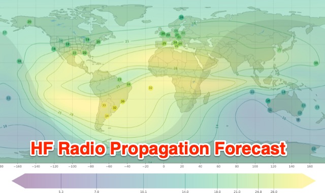 Understanding high-frequency (HF) skywave propagation is crucial for amateur radio operators seeking to optimize long-distance communications. This resource details the fundamental principles of HF radio propagation, including the properties of electromagnetic waves, the characteristics of various HF bands, and distinct propagation modes such as skywave, ground wave, and line-of-sight. It places significant emphasis on the ionosphere's pivotal role in refracting HF waves, explaining how solar activity directly influences ionospheric conditions and, consequently, propagation paths. The resource integrates real-time monitoring capabilities, featuring dynamic charts and data from DX clusters, WSPRnet, and the Reverse Beacon Network, which allow users to track current band activity and propagation conditions globally. It also delves into advanced topics like Near Vertical Incidence Skywave (NVIS) and gray line propagation, providing insights into ionosonde data and various propagation prediction models. The site presents a detailed analysis of solar-terrestrial interactions, geomagnetic indices, and space weather phenomena, illustrating their direct impact on HF communication reliability. Practical tools and applications are highlighted, including real-time QSO planners, online Maximum Usable Frequency (MUF) maps, and alerts for solar flares or geomagnetic storms. The guide systematically breaks down complex concepts into accessible chapters, offering a structured approach to learning about ionospheric regions, diurnal and seasonal effects, and the interpretation of propagation indicators like foF2, MUF, and Lowest Usable Frequency (LUF). This makes it a robust reference for hams aiming to deepen their technical understanding and improve operational effectiveness.
 -
 Details the offerings of Ham Buerger Inc., a company founded in 1965 to support the amateur radio community with communications products. The business provides a range of equipment, including Uniden Digital scanners, and maintains a section for equipment blow-out sales that feature professional 2-way radios and cell phones. Additionally, the company stocks hard-to-find NuTone products and provides repair services for most NuTone equipment. The site also references an Amateur Radio Band Plan and links to other ham radio resources, alongside a new product offering for RV and marine toilets, indicating a diversification beyond core amateur radio supplies.
 -
 JJ0DRC's HF multi-band delta loop antenna project, initially conceived during the waning peak of Cycle 23, addresses the common challenge of achieving effective DX operation from a small residential lot in Japan. Dissatisfied with a ground plane antenna's performance in SSB pile-ups, the author sought a beam-like solution without a tower, drawing inspiration from a JJ1VKL article in CQ Ham Radio Sep. 2000. The antenna, constructed in October 2000, employs two 7.2-meter fishing rods (37% carbon fiber, reinforced with cyano-acrylate glue and aluminum tape) and 1mm enameled wire, fed by an Icom AH-4 external antenna tuner. While the exact beam pattern remains unmeasured, JJ0DRC observed a significantly higher callback rate compared to dipole antennas, particularly on higher bands. The system's circumference length of 15-20m is crucial for maintaining a good beam pattern across HF bands, though performance on lower bands like 80m, 40m, and 30m becomes less directional as the length deviates from a full wavelength. Ongoing maintenance addressed degradation issues, including aluminum tape cracking and wire breakage at connection points due to strong winds (often exceeding 10-15m/s in winter). The author reinforced rod connections with IRECTOR PIPE SYSTEM components and INSU-ROCK ties, and improved wire attachment methods using Cremona rope and epoxy bond to enhance durability.
 -
 Presents the design and construction of the OK2FJ Bigatas, a portable, automatically tuned vertical antenna covering 80 through 10 meters. It details two distinct control systems: one utilizing BCD band data from Yaesu FT-857/897 transceivers, and another employing voltage level sensing for the Yaesu FT-817. The resource provides specific instructions for building the antenna's radiating element, loading coil with switchable taps, and the control circuitry, emphasizing the use of readily available components. The article outlines the physical construction of the antenna, including the use of duralumin tubes for the radiator and a PVC tube for the coil form. It specifies coil winding details, tap points, and the integration of radial wires for ground plane operation. The control electronics section provides schematics and component lists for both the BCD decoder (using a 74LS42 IC) and the voltage comparator (using an _LM3914_ bargraph driver), enabling rapid, automatic band switching without the minute-long tuning delays common in other systems. Crucially, the antenna achieves rapid band changes, with typical SWR values centered on common operating segments, such as **3.7 MHz** for 80m SSB. It also discusses modifications for CW operation on 80m and the trade-offs between antenna efficiency and full-range automatic tuning on higher HF bands, where manual adjustment of radiator length is suggested for optimal performance on 15m, 12m, and 10m. The resource includes construction photos and a discussion of cable requirements for reliable operation.
 -
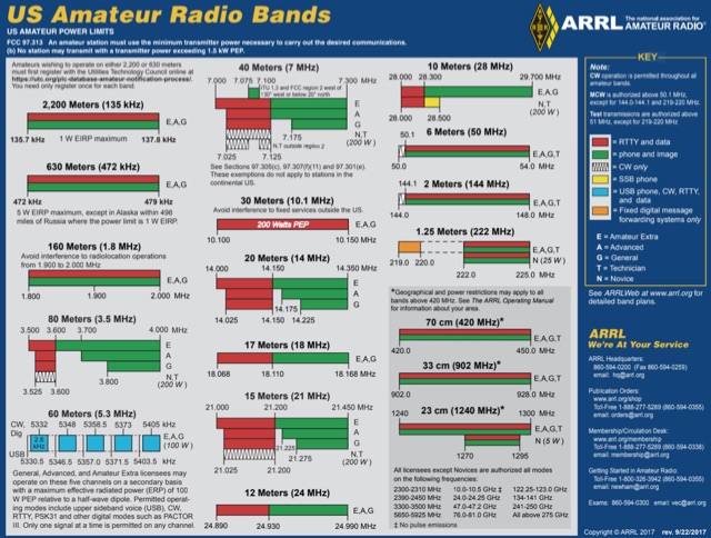 US Amateur Radio Band Plans by ARRL
 -
 The **ARRL Contest Calendar** presents a detailed schedule of upcoming amateur radio competitions, encompassing both ARRL-sponsored events and significant non-ARRL contests. It provides essential operational details for each entry, such as specific operating periods, eligible bands, and permitted modes, enabling contesters to plan their participation effectively. The resource also links to official rules, soapbox reports, and QST results, offering a comprehensive overview of past and future contest activity. Users can navigate through monthly listings to identify contests of interest, with direct access to detailed information pages for each event. The calendar serves as a central hub for contest operators seeking to confirm dates, understand exchange requirements, and review post-contest analyses. Its utility extends to both seasoned contesters and those new to competitive operating, providing a structured approach to contest participation. The platform integrates various contest-related resources, including links to **Contest Corral** entries for non-ARRL events, ensuring a broad scope of coverage. This aggregation of information streamlines the process of finding contest schedules and associated documentation, making it a practical tool for the amateur radio contesting community.
 -
 A _Topfkreis_ antenna, also known as a "bicycle pump" antenna, is presented as a simple vertical design for the 70 cm band. This variant of the J-pole antenna is notable for not requiring a ground plane, simplifying deployment. The construction details specify using aluminum tubing for the radiating element, with precise measurements for the quarter-wavelength outer tube (32 mm diameter) and the three-quarter wavelength inner sliding tubes (10 mm and 8 mm). Feeding is via a 50-ohm coaxial cable connected 90 mm from the base of the central tube. This design can achieve a gain of **4 to 6 dB** when properly tuned using the adjustable radiating element. The article details the fabrication of a critical aluminum washer, suggesting a method using a hole saw and a drill press as a lathe for precise adjustment. The illustrated example is specifically for the 70-centimeter band, and the author, Pop, clarifies construction points in the comments, including material choices and assembly techniques, ensuring a robust build for VHF/UHF operation.
 -
 Operational testing of a 10.07-meter portable HF vertical antenna, constructed from telescoping aluminum tubing (36, 32, 22, 17 mm diameters), yielded SWR measurements below 1.5 across multiple bands. Initial trials on 14.150 MHz showed an SWR of 1.6, while 7.075 MHz was problematic. Subsequent adjustments, including a 13 cm extension to the radiating element, improved performance, enabling operation on 6, 15, and 40 meters without a balun, and adding 12 meters with a balun. The design prioritizes portability, allowing transport in a standard vehicle and single-person deployment. Four 10.07-meter radials are connected at the base to enhance ground plane effectiveness. The article details the mechanical assembly, including custom adapters for tube transitions and a PVC sanitary tube sleeve for base insulation, ensuring robust field deployment. Final SWR measurements, documented with an _MFJ-259_ antenna analyzer, confirm operational ranges: 6.800-7.500 MHz (SWR < 1.5), 20.800-22.500 MHz (SWR < 1.5), and 48.800-51.500 MHz (SWR < 1.5) without a balun. With a balun, the antenna achieved SWR < 1.5 on 13.750-15.000 MHz and 24.890-28.350 MHz, demonstrating its versatility for portable _DXpeditions_.
 -
 A GSM1800 Moxon Square antenna project is presented, detailing its construction using three 1.5mm copper wire pieces for the reflector and dipole elements. The design inherently offers a 50-ohm feedpoint impedance, allowing direct connection to 50-ohm coax without complex matching networks like baluns or gamma matches, which are prone to high attenuation at 1.8 GHz if not precisely built. The resource includes a construction plan, expected **SWR plots**, and **radiation patterns** for the GSM 1800 band, specifically covering the 1710-1785 MHz transmit (red zone) and 1805-1880 MHz receive (blue zone) segments. The SWR remains below 2:1 across the entire GSM 1800 band, with the main lobe consistently achieving 5-6 dBi gain. While the radiation pattern shows some changes across the band, these primarily affect the back of the antenna, maintaining consistent forward gain. Practical considerations for high-frequency operation are emphasized, such as minimizing coax length (e.g., under 1 meter for RG-174) and selecting appropriate connectors like N, SMA, or BNC to mitigate significant attenuation. The article also discusses direct connection to the phone's RF PCB for minimal loss and notes observed signal strength variations with antenna orientation despite crossed polarization at cell sites.
 -
 A Moxon rectangle antenna design for the 11-meter band is presented, offering a compact and lightweight solution for directional HF DX operation. This two-element parasitic array, popular among amateur radio enthusiasts, provides considerable directional gain and lower noise on horizontal polarization. The design is suitable for both 27 MHz Citizens Band (CB) and the lower portion of the 28 MHz amateur radio band, making it versatile for operators interested in either service. Construction can utilize materials like bamboo, squid poles with wire elements, or aluminum tubing on a central boom. The article includes a plan view diagram with specific dimensions (A-E) in centimeters and inches for building the antenna, such as a 392.09 cm (154 3/8 inch) driven element. The Moxon configuration inherently presents a 50 Ohm load to the transceiver, often eliminating the need for an external matching unit or balun. Performance data for an antenna mounted at approximately 30 feet indicates a gain of 10-11 dBi and a frequency range of 27.300 MHz to 28.300 MHz. The design is noted for its excellent front-to-back rejection, with tested signal drop-offs from S5-S7 to S2 when turned, demonstrating effective suppression of unwanted signals.
 -
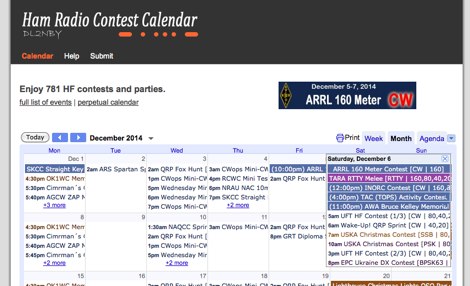 The DL2NBY Contest Calendar, leveraging the Google Calendar system, presents approximately 400 **HF amateur radio contests**, detailing their dates and rules. It covers a broad spectrum of operating modes, including CW, SSB, and various digital modes like RTTY. The calendar integrates contest information from major organizations such as ARRL and DARC, providing a centralized repository for contest operators. This resource offers the capability to integrate contest events directly into a user's personal Google Calendar, streamlining contest planning. It functions as a comprehensive schedule, allowing operators to review upcoming events and prepare for participation across different bands and modes. The calendar's structure facilitates quick access to contest specifics, aiding in strategic contest operation.
 -
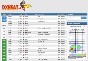 Over 15 years of experience in DXing and contesting informed the development of _DXHeat_, a responsive web DX Cluster and analytics platform. This service delivers real-time DX spots, accessible on both desktop and mobile devices, featuring intuitive filtering capabilities. Users can quickly narrow down spots by band, mode, or specific callsign, streamlining the search for rare DX or contest multipliers. The platform integrates data from various sources, including traditional telnet clusters, the Reverse Beacon Network (_RBN_), and _PSK Reporter_, offering a comprehensive view of propagation and activity. Beyond live spotting, DXHeat provides extensive cluster analytics for individual callsigns, allowing operators to research past activity and propagation trends. This deep dive into historical data can be particularly useful for planning future DXpeditions or optimizing contest strategies. The interface is designed for serious DXers, prioritizing quick access to relevant information and robust data analysis.
 -
 DK7ZB provides detailed construction plans for Moxon antennas utilizing tapered aluminum tubing, specifically outlining dimensions for 50 MHz, 28 MHz, 24 MHz, and 21 MHz bands. The resource emphasizes maintaining specific taper lengths for optimal performance and describes a tuning method involving symmetrical element shifts. It also addresses stacking considerations, noting that two Moxons can be stacked 1m apart with a 90° rotation to avoid severe detuning, unlike co-planar mounting. Performance figures for the 50-MHz Moxon include a gain of **4.1 dBd** and a front-to-back ratio of _30 dB_. The construction utilizes copper fittings for element connections, with a recommendation to varnish edges against corrosion. The page features images of built antennas by _DK8UH_ and VK2QO, illustrating practical implementations for the 6-meter and 10-meter bands, respectively.
 -
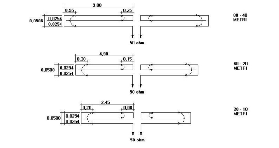 The resource details the historical development of the Morgain antenna, tracing its origins to Virginia in the 1960s and its subsequent global adoption among radio amateurs. It describes the Morgain as a dual-band wire antenna known for its reduced footprint and modest gain characteristics. The content includes discussions on various homebrew projects and design variations available online, providing context for its continued relevance in amateur radio. The article presents a historical overview rather than specific construction plans, focusing on the antenna's evolution and general design principles. It highlights the antenna's enduring appeal due to its performance attributes and compact size, making it suitable for various operating environments.
 -
-
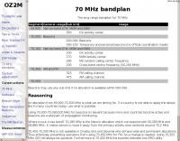
 DX_Central, a compact desktop application, provides amateur radio operators with critical propagation data by aggregating solar statistics and imagery from various authoritative sources. This includes real-time information from agencies like NOAA and NIST, offering insights into current space weather conditions that directly impact HF propagation. The software is designed for both Linux and Windows operating systems, making it accessible to a broad range of hams. It presents a concise overview of solar activity, which is essential for planning DX operations and understanding band openings and closures across the HF spectrum. Operators can utilize the displayed solar flux index, K-index, and other relevant parameters to make informed decisions regarding their operating times and target bands, optimizing their chances for successful long-distance contacts.
 -
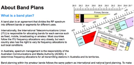 Australian amateur radio band plans in pdf format
 -
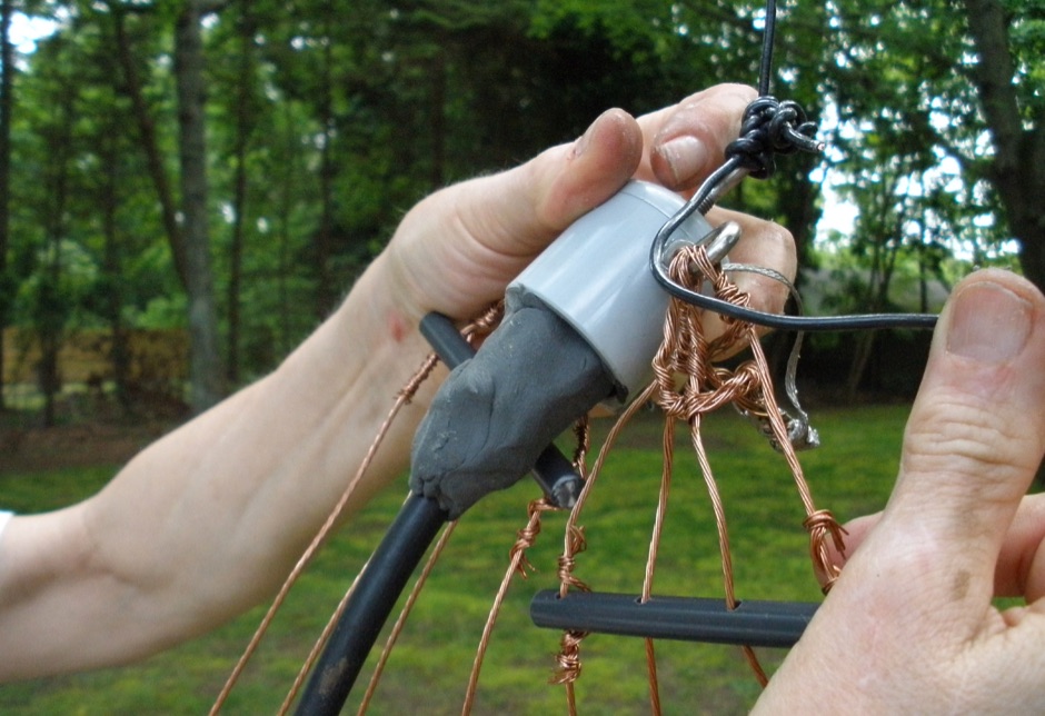 Interesting article on multiband fan dipoles. This article give an overview on designing this wire antenna, and planning a robust installation and proper feed line. Includes notes on setting up a commercial fan dipole antenna and on how diy your own.
 -
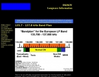 The 2.1 kHz wide European LF allocation between 135.7 and 137.8 kHz is detailed in this observed band plan, offering guidance for activity within this narrow segment. It specifically addresses the challenge of locating weak signals, such as those from Slow-CW stations, which can have bandwidths of only a few Hertz. The resource emphasizes the utility of precise frequency knowledge when operating with narrow DSP filters, like a 30 Hz filter for CW, to differentiate multiple stations within a very small band segment. The plan, though not officially recognized, provides practical orientation for operators, particularly those new to the _LF band_. It references a similar plan published by the _RSGB_ in the January 2000 issue of _RADCOM_, suggesting a community-driven approach to band organization. The content highlights the importance of spectral awareness, noting that multiple stations can occupy minimal bandwidth, a concept illustrated by spectrographic analysis.
 -
 The resource details the construction of a 3-element Yagi antenna specifically designed for the 6-meter band, providing coverage across 50-54 MHz. This antenna design, originally featured in _QST_ August 2007, emphasizes a short boom configuration while maintaining a wideband response. Key specifications include a 50 Ohm SWR of less than 2:1 across the entire band, achieved through specific element lengths and spacing. The design utilizes aluminum tubing for elements and boom, with detailed dimensions provided for the driven element, director, and reflector. Performance characteristics indicate a forward gain of approximately 7.5 dBi and a front-to-back ratio of 18 dB at 50.125 MHz, according to _NEC2_ modeling. The antenna's compact size, with a boom length of 1.83 meters (6 feet), makes it suitable for portable operations or installations with limited space. Construction involves standard amateur radio workshop tools and materials, with a gamma match for impedance transformation to 50 Ohms. The design prioritizes ease of construction and repeatable performance for the 6-meter enthusiast.
 -
 The Cushcraft X7 Tribander assembly and installation manual (P/N 951470, 12/97) provides comprehensive instructions for constructing this 20-15-10 meter seven-element beam antenna. It details the sequential assembly of boom sections, individual elements, and the feed system, including the _MNX7 Matching Network_. The document emphasizes critical safety precautions regarding power lines and RF exposure, alongside recommendations for proper antenna system planning and grounding. Key sections cover verification of parts, detailed boom assembly using specific aluminum tubing (e.g., BA, BB, BC, BD, BE) and brackets, and element construction with various aluminum tube sections (e.g., EA, EB, EC, ED, EE, EF) and traps like the _15 Meter Director Trap_ (TB) and _10 Meter Director Trap_ (T9). It also specifies the use of _NOALOX® conductive lubricant_ for telescoping sections and hardware to prevent galling. The manual outlines the feed system assembly, which includes feed-straps (FL1, FL2, FL3), tuning-tube insulators, and the matching network. It also mentions the optional X740 40-meter add-on kit, which requires a separate coax feed. Detailed diagrams and parts lists with metric equivalents facilitate accurate construction and ensure the antenna performs as specified.
 -
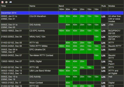 The _HF Digital Contest Calendar_ provides a monthly schedule of amateur radio contests specifically for digital modes on HF bands. It lists various RTTY contests and other digital mode events, offering a structured overview for contesters. The calendar includes details relevant to participation in events such as those organized by ARRL and DARC. This resource assists operators in planning their contest activities, focusing on the digital segment of the HF spectrum. It serves as a quick reference for upcoming digital mode competitions, facilitating preparation for these operating events. The calendar aims to consolidate information on digital contests, which often feature specific exchange requirements and scoring methodologies.
 -
 Presents _HamQTH_, a free online callbook and callsign server, which provides rapid XML access for various logging programs, enabling seamless integration for amateur radio operators. The service includes features such as recent activity logs, propagation predictions, and support for multiple languages, making it a versatile tool for DXers and contesters. It also offers detailed information on callsigns, including US states, counties, IOTA, WAZ, and ITU zones. Users can leverage _HamQTH_ for efficient log searching and to monitor current band conditions, aiding in planning DX operations and contest strategies. The platform's XML interface facilitates automated lookups, streamlining the process of identifying stations and gathering essential QTH data. Petr Hlozek, OK2CQR, developed this resource, reflecting practical experience in amateur radio data management.
 -
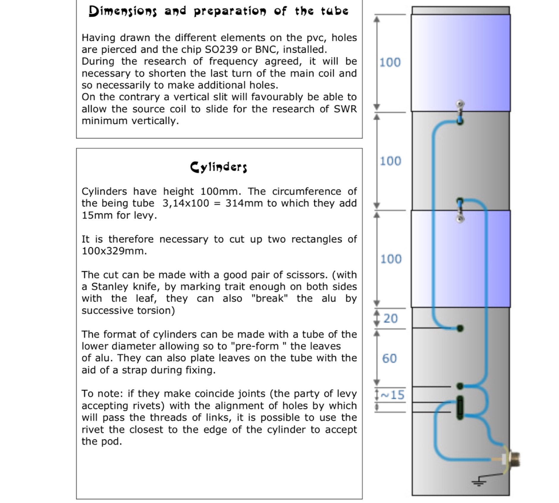 A project of a small antenna, just 50 cm for the 7 MHz band. An EH Antenna plan for the 40 meters band