Search results
Query: element diameter
Links: 16 | Categories: 0
-
 This drawing shows a simple 10 meter wire J-pole antenna designed for 28.4 MHz. It is a vertical, end-fed Zepp-style antenna made from common materials and intended for easy home construction. The main radiating element is a straight length of stranded copper wire, either 14 or 18 gauge, cut to about 16.5 feet. At the top, the wire is supported by an insulator, allowing the antenna to be hoisted vertically. The matching section is made from 450-ohm ladder line, approximately 7 feet 9.5 inches long, and shorted at the bottom. This matching stub transforms the impedance so the antenna can be fed with coaxial cable. The feed point is tapped about 6 inches above the bottom of the stub, with the shield and center conductor connected at the proper points. A choke balun is formed with five turns of RG-58 coax in a 4-inch diameter loop to help reduce unwanted RF on the feed line. The drawing notes that this antenna has about 0 dBd gain, similar to a dipole, but offers an omnidirectional pattern and low-angle radiation when installed high. Its main advantage is practical performance, simple construction, and effective coverage for 10 meter operation.
 -
 The total length of this antenna is 41m, height is about 11m, and diameter of element is 2mm. JA7KPI modified this antenna originally used as Inverted-V type of 80m band Dipole. Works on 40 - 80 meters band with acceptable swr.
 -
 The 30/40 meter **vertical antenna** project by IK4DCS details the construction of a shortened, self-supporting design, reaching a total length of 5 meters. The antenna incorporates a linear loading section and a coaxial cable trap for 30 meters, based on the "Antenne Volume 2°" text by Nerio Neri (page 223). The design uses six radials, three for each band, positioned at approximately 90° inclination and at least one meter above the roof or ground, connected via a 1:1 balun at the feed point. Mechanical construction utilizes aluminum tubing, with a 2.30-meter primary radiator section (30 mm diameter) joined to a second part using a Teflon insert and a PVC sleeve for rigidity. The linear load, approximately 3.70 meters long, accounts for a 30% physical shortening of the quarter-wave element. A capacitive load, made from three 50 cm radials, is integrated into the 40-meter top section for fine-tuning. Final adjustments involved radial inclination for 40 meters, as initial testing showed increased SWR and interference on 30 meters due to nearby resonant structures. The author emphasizes the importance of clear space for optimal performance and provides drawings and photos to clarify the build process.
 -
 A rotary trapped-dipole for 17 and 20 meters, as described by IZ7ATH, presents a practical solution for multi-band HF operation. The author, Talino, recounts his experience building this antenna for IK7ZCQ, detailing the evolution from an initial concept involving a grounded-driven element and gamma-match to a direct-fed, non-grounded design. His pragmatic approach, adapting available materials, is evident throughout the construction narrative, particularly with the use of eight tapered aluminum pipes for the driven element. Construction specifics include precise measurements for the aluminum tubing, with diameters ranging from 30 mm down to 16 mm, and a critical note on reducing tip thickness for weight optimization. The _traps_, initially a concern, are fabricated using 8 turns of RG58 coax on a 27 mm support, tuned to resonate at 18.1 MHz using a dip-meter. Talino emphasizes sealing the traps with RF glue and PVC tape to prevent water ingress, a crucial step for longevity. Field test results, conducted on a 10-meter pole in a clear garden environment, showed an SWR of 1.2:1 on 17 meters and 1.5:1 at 14.200 MHz. While SWR varied slightly when installed at Mario's QTH due to nearby objects, the antenna's performance remained commendable. The final half-dipole length is 46 cm for the 18 MHz tips, and the total weight is under 6 kg, with potential for further reduction.
 -
 The BV6 50 MHz Yagis resource details the construction of two distinct Yagi antenna designs for the 6-meter band, specifically a 1-wavelength (1wl) model and a 2.1-wavelength (2.1wl) model. The 1wl Yagi, with a boom length of 5.850m, achieves a gain of **9.4 dBd**, while the 2.1wl Yagi, spanning 12.90m, boasts a gain of **11.9 dBd**. These designs adhere to a proven methodology for optimizing current slope and maintaining constant phase delay across parasitic elements, ensuring high gain per boom length and an _excellent pattern_. Both designs target a 50-ohm input impedance, facilitating straightforward feeding with a robust folded dipole. Final verification using NEC-II software confirmed the antennas' exceptional stacking capabilities, yielding stacking gains exceeding **5.8 dB** for a 2x2 array with minimal mutual detuning. The resource provides common mechanical data, including boom and element diameters, and specifies element lengths corrected for boom diameter. While the original _DUBUS Technik V_ publication contained incorrect element lengths, this resource provides the accurate dimensions for proper construction, emphasizing the use of readily available materials for cost-effective amateur radio deployment.
 -
 An homemade portable vertical antenna with a trap near the mid point of the main element. The trap is made with 42mm diameter PVC pipe with 9 turns of wire on it
 -
 This document details the design and construction of a Vinecom 6N4 dual-band Yagi antenna for the 50MHz (6-meter) and 70MHz (4-meter) amateur radio bands. The antenna features 9 total elements (4 elements for 50MHz, 5 elements for 70MHz) on a 4.236-meter aluminum boom. Computer simulations using MMANA software predict 7.21 dBd gain on both bands with front-to-back ratios of 16.01dB (6m) and 15.37dB (4m). The design uses 12.7mm diameter elements mounted on a 32mm square boom, weighing 5.7kg total. Practical measurements with an MFJ-269 analyzer confirmed good SWR performance across both bands after element length adjustments.
 -
 This PDF document details the construction of a **70 MHz** Big Wheel antenna, a horizontally polarized omnidirectional array. The design utilizes three full-wave loops, each approximately **2160 mm** in diameter, arranged in a triangular configuration. The resource provides mechanical dimensions for the antenna elements and a comprehensive bill of materials, specifying component quantities and types, such as M8 stainless steel bolts, 15x15x1.5 mm square aluminum tubing for spacers, and 8 mm aluminum rod for the arcs. The central hub is constructed from two 160x160x8 mm aluminum plates, with four 40 mm long polyamide insulators supporting the radiating elements. The feed system incorporates a 50 mm diameter aluminum pipe for mounting and a matching stub constructed from a 120x20x2 mm aluminum sheet, connected via M8x10 mm bolts. The resource includes a diagram illustrating the mechanical dimensions and assembly points, including the N-connector fixing point and the center conductor attachment. The project was published on May 25, 2011, by Peter OE5MPL and Rudi OE5VRL. DXZone Focus: PDF | 70 MHz Big Wheel | Mechanical Dimensions | **2160 mm** loop diameter
 -
 A presentation of the Yagi Antennas, and other interesting tid-bits by Brian Mileshosky. The document provides an in-depth exploration of the Yagi-Uda antenna, detailing its historical development, design principles, and performance characteristics. Originally described in the 1920s, the Yagi antenna features a driven element and parasitic elements, including reflectors and directors, which collectively determine its behavior. The document highlights how element lengths, diameters, and spacing influence gain, impedance, and directivity. It also discusses the antenna's reciprocal nature and presents data on typical gain values for various element configurations. Additionally, the text covers practical considerations, such as the construction of a "Tape Measure Yagi" for amateur use, and touches on related antenna types like dipoles and their application in Near Vertical Incident Skywave (NVIS) communication.
 -
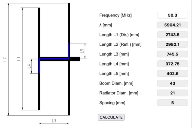 Online HB9CV antenna calculator, accept as input the desired resonating frequency and provides dimensions for spacing and length of each element, including boom and radiator diameter.
 -
 Elements are aluminum TIG soldering rods 4.0mm of diameter, almost 1m long, these objects are light, thin and flexible based on the RZ9CJ Design
 -
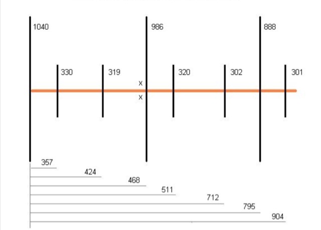
 A basic YAGI UDA online antenna calculator, accept as input frequency, number of elements, diameter of parasitic element and boom diameter. This online calculator will generate a basic design data including each element length and spacing.
 -
 A mircovert antenna assembled for the 40m version of the DL7PE antenna. A one meter long aluminum tube with 24mm diameter is used for the base (element 1) and a 50cm aluminum tube with 20mm diameter for element 2 (the extention). A pvc pipe, 34cm long and with a diameter of 38mm, is used to wind the coil on (1mm enamelled copper wire).
 -
 This project involves constructing a dual-band Moxon antenna, optimized for ham radio enthusiasts, with functionality on both the 10-meter and 6-meter bands. The antenna is designed to operate using a single 50-ohm feedpoint, acting as a mini-beam on 28 MHz (10 meters) and as a 2-element Yagi on 50 MHz (6 meters). Performance-wise, it offers a 4.0 dBd gain on 10 meters and 4.3 dBd on 6 meters, with impressive front-to-back ratios of 30 dB and 11 dB, respectively. Builders like Aleks (S54S) and Marcio (PY2OK) have successfully brought this design to life using the provided specifications. Aleks noted that bending the corners of the structure proved especially useful during assembly. The project comes with a detailed parts list, highlighting the use of aluminum tubes with different diameters and lengths to form essential components like the reflectors and radiators. For those looking to fine-tune the antenna, adjustments can be made by altering the length of certain parts that fit into larger tubes. The feeding system is equipped with a balun to accommodate different power levels, making the design versatile enough to handle outputs of either 300 watts or 1 kilowatt.
 -
 This is a design based on the QuickYagi 4 software by WA7RAI with some changes for practical reasons. The beam uses 6.5 metres of standard 25mm square boom, 12mm diameter elements without tapers. The actual boom length used is 6.3 metres and all parts are readily available.
 -
 YAGio 1.01 is a Windows-based software for designing DL6WU long Yagi antennas on VHF and UHF frequencies. It supports Windows 2000, XP, Vista, 7, and likely 8. Using keyboard commands, users input specifications such as frequency, gain, and element diameters, and YAGio generates the design. You can download latest Yagio version from this page. Results can be saved in YIO, NEC, YAG, MMA, and YC6 formats, or printed directly.