Search results
Query: igate setup
Links: 11 | Categories: 1
-
 This resource details the fundamental aspects of deploying longwire antennas, emphasizing ease of construction and installation for shortwave listening (SWL) and broadcast reception. It covers wire gauge selection, suggesting 14 to 24 AWG for general use, with heavier gauges (14-20 AWG) for permanent outdoor installations. Guidance is provided for various deployment scenarios, including indoor setups where the wire can be run around a room, temporary outdoor installations from balconies using light 18-24 AWG wire, and permanent outdoor configurations requiring higher placement and slack for tree movement. Feeding methods are discussed, recommending coaxial cable (50-75 ohms) to mitigate man-made interference, with instructions for connecting only the center conductor to the longwire. Safety precautions are highlighted, particularly avoiding contact with power lines and conductive materials, and managing static electricity buildup by unplugging the antenna after use and bleeding off charges before connection. The article also advises against using outdoor longwires during thunderstorms or snowstorms due to static and lightning risks. Optimal height considerations are presented, advocating for the highest safe placement, ideally a couple of feet above underlying structures, to maintain free air space. The text mentions a personal setup with one end at a roof peak (20 feet) and the other at a 17-foot mast, illustrating practical deployment without strict height requirements beyond safety and clearance.
 -
 The W1TAG LF Receiving Loop is a specialized antenna project for LF reception, designed to mitigate local noise and enhance weak signal pickup on the lower frequencies. This square loop, measuring 6 feet per side, utilizes 14 turns of #12 THHN wire wound on a PVC frame, offering a robust mechanical structure. The design incorporates a series-tuned circuit with a coupling transformer, allowing for tuning from over 400 kHz down to _45 kHz_ using a switched capacitor bank. Construction details include the use of 1.5-inch PVC pipe for the frame, with specific measurements for spreaders and drilled holes for wire threading. The two 7-turn sections of wire are connected at the center, providing an option for a center tap. The loop rotates on a 1-inch steel pipe, enabling directional nulling of noise sources. The tuning unit, housed in a box clamped to the PVC, employs a 1:2 step-up transformer wound on an _FT-82-77 core_ and uses relays to switch capacitance values from 50 pF to 6400 pF, providing precise frequency adjustment. The current setup connects to the shack via 100 feet of RG-58, feeding into a W1VD-designed preamp, with plans for a balanced, shielded twisted pair cable upgrade.
 -
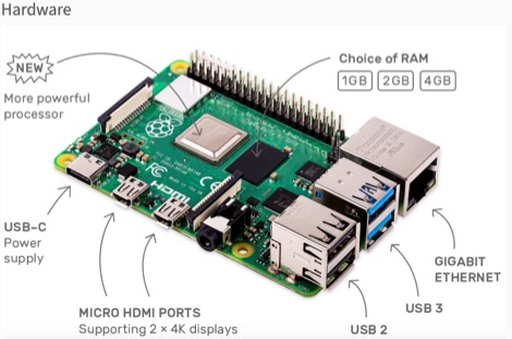 This resource is an online tutorial focused on setting up the Raspberry Pi for amateur radio applications. It covers the installation and configuration of various software packages tailored for digital communications and protocols, including _Packet Radio_ with Hamlib and Direwolf, as well as data modes like FLDigi and WSJT-X. The guide also details the integration of hardware components such as GPS clocks for time synchronization and real-time clocks for enhanced functionality. Users will find instructions for installing software like GPredict for satellite tracking and GQRX for software-defined radio (SDR) applications. The tutorial emphasizes practical steps, including the use of command-line inputs in the Raspberry Pi OS terminal, and provides troubleshooting tips for common issues such as faulty SD cards or insufficient power supplies. Operators are encouraged to explore various applications, including APRS iGates and WSPR beacons, to enhance their ham radio experience. The material is designed for licensed amateur radio operators with basic knowledge of electronics and computing.
 -
 Operating in a Single Operator Two Radios (SO2R) setup, especially with beverage antennas, often exposes the receiving radio's front-end to significant RF energy from the transmitting radio. This resource details a practical, homebrew receiver protection circuit designed to mitigate this risk. The core of the design involves a non-inductive 2W 22 Ohm carbon composition resistor in series with the RX antenna line, followed by two stacks of four fast-switching diodes (e.g., _1N914_) configured in opposite polarizations. This arrangement effectively clamps the incoming voltage to approximately 2.8 V peak-to-peak, safeguarding sensitive receiver input components. The series resistor plays a crucial role by absorbing excess power, preventing the diodes from exceeding their current ratings and potentially failing open, which would leave the receiver unprotected. The author, _N4KG_, measured up to 50 watts of coupled power between 80M slopers on the same tower, highlighting the necessity of such protection. The design is presented as a cost-effective solution to prevent damage to receiver input transformers, with the author noting successful protection of a receiver even after a resistor showed signs of overheating. This simple circuit can be integrated via a transverter plug, offering a robust defense against high RF input.
 -
 This article addresses the issue of unwanted RF in amateur radio setups and introduces a practical method to measure common-mode currents (CMC) using a homebuilt RF meter. The meter, constructed with readily available materials, measures unwanted RF on the coaxial cable shield by inductively coupling to the shield using a split-bead ferrite. The article provides detailed instructions on building the meter, interpreting measurements, and using ferrite chokes to mitigate RF interference. Emphasis is placed on the importance of verifying CMC levels and installing chokes to improve equipment performance.
 -
 Analyzes the operational dynamics of the _IARU R1 VHF contest_, the world's largest 2-meter contest, focusing on factors enabling top performers to maintain consistent results amidst declining overall activity. The resource investigates the physical constraints that limit higher point totals, examining how technical capabilities, increased interference, and evolving station setups contribute to contest outcomes. It provides insights into the strategic and technical aspects of achieving high scores, such as the **1,000,000+ point** totals observed from leading stations. Compares the performance of various stations over time, highlighting the sustained success of top contenders and speculating on future trends in VHF contesting. The analysis delves into specific operational strategies and equipment choices that differentiate high-scoring stations, offering a detailed look at the competitive landscape. It also considers the impact of propagation conditions and operator skill on final scores, providing a comprehensive overview of the contest's intricate mechanics and the pursuit of maximum QSO points.
 -
 **APRS TX I-Gate with APRX and the Universal Radio Controller** This project explores the creation of an APRS TX I-Gate to improve message delivery in amateur radio communications. Initial experiments involved configuring a picoAPRS v4 and later a G1LRO Universal Radio Controller (URC) with a Quansheng UV-K5 as digipeaters. While both setups successfully retransmitted signals, they failed to receive incoming APRS messages. To address this, a Raspberry Pi Zero running Debian and APRX-2.9 was repurposed to provide network connectivity, transforming the URC into an effective TX I-Gate for seamless APRS message handling.
 -
 Integrating a _Software Defined Radio_ (SDR) into an existing ham radio setup involves connecting it with a standard transceiver (TRX), power amplifier (PA), and antennas. The core component is a splitter box that facilitates the connection between the TRX and the SDR, allowing for simultaneous operation without modifying existing equipment. In receive mode, the splitter ties the antenna inputs of both the TRX and a direct conversion receiver (DC RX) together. During transmission, the DC RX input is grounded via a fast telecom relay controlled by the transceiver's -SEND signal, incorporating a 10ms delay for safety. The splitter box includes a 3.7 dB input attenuator for impedance matching and acts as a protective fuse for the DC RX input. Ground loops are mitigated using common mode balun transformers, while the DC RX input is insulated with a broadband transformer. An audio switch box complements the setup, enabling users to listen to either the main transceiver, the SDR output, or both simultaneously. This configuration ensures noise immunity and safety, with the splitter housed in a screened box made from PCB material. On-air tests, such as the CQ WW 160m CW DX Contest, demonstrate the system's effectiveness, showcasing the SDR's ability to handle crowded band conditions with superior selectivity and dynamic range. The SDR's narrow bandwidth filters and waterfall display provide significant advantages, allowing operators to detect weak signals amidst strong interference. The integration of SDR with conventional radios offers enhanced operational flexibility and performance in challenging environments.
 -
 The ICOM IC-705, a popular QRP transceiver for portable operations, often presents unique challenges for field deployment. This resource details practical solutions for common portable setup issues, particularly for _Parks on the Air_ (POTA) activations. It describes a custom bracket for connecting antennas to the IC-705 through a backpack's antenna flap, utilizing a BNC female-to-female chassis mount connector to mitigate cable tangles. The author shares experiences with a DIY magnetic loop antenna, noting its ease of tuning with the IC-705 and successful CW contacts on 40 and 20 meters over distances exceeding **1000 miles**. Another modification presented is a strain relief solution for the microphone cord, replacing the standard spring clip with an easier-to-attach method. The page also mentions using a _Wolf River Parks antenna_ for POTA activations and references the QRPGuys DS-1 antenna as another portable option. Firmware updates and integration with an LDG Z11-Pro II auto-tuner are also discussed.
 -
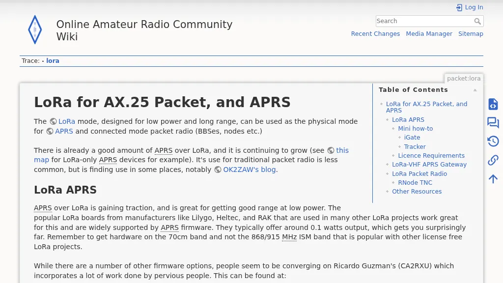 The resource details the use of LoRa for AX.25 packet radio and APRS, focusing on practical implementation. It specifies UK LoRa APRS frequency and modulation settings: **439.9125 MHz**, 125kHz bandwidth, SF12, and CR 4/5. The content provides a mini how-to for setting up an iGate using VS Code and _Platformio IDE_, with specific instructions for a Lilygo LoRa32 V2.1_1.6 board, including configuration for Wi-Fi, beaconing, and APRS-IS passcode. It also covers tracker setup using a Lilygo T-Beam Supreme, detailing firmware flashing and configuration for mobile operation. The guide differentiates LoRa APRS from traditional connected-mode packet radio, explaining why common LoRa APRS firmware is unsuitable for full AX.25 packet due to its TNC2-style payload structure. It explores alternative solutions for true LoRa packet radio, such as using an _RNode_ TNC or Raspberry Pi LoRa TNCs, and provides commands for RNode firmware installation and configuration for serial KISS operation. The resource also touches upon licensing requirements for unattended Digipeaters in the UK, noting the need for ETCC coordination and MB7Uxx callsigns.
 -
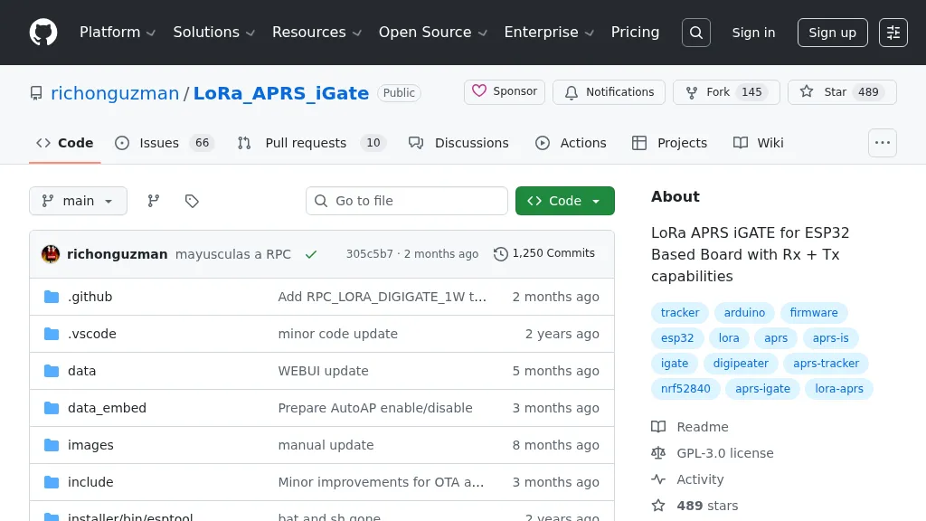 Demonstrates firmware for microcontrollers like the _ESP32_ to implement a LoRa APRS iGate and Digipeater. This project leverages LoRa for packet radio communication, allowing amateur radio operators to bridge the gap between LoRa-enabled APRS stations and the global APRS-IS network via WiFi. It details the setup for both iGate and Digipeater modes, including features like transmitting APRS-IS packets over LoRa to local stations and a 30-second buffer in digipeater mode to prevent packet storms. This firmware offers an Ultra Eco Mode, achieving current consumption between **7mA** and **13mA**, making it suitable for remote, battery-powered deployments. The integrated WebUI simplifies configuration and management, providing an accessible interface for hams to deploy and maintain their LoRa APRS infrastructure. It supports sending weather telemetry packets and adheres to APRS protocols, released under the GPL-3.0 license.