Search results
Query: modeling software
Links: 21 | Categories: 0
-
 Antenna Scatterers Analysis Program, is a Free general purpose antenna analysis software program for numerical electromagnetic antenna design, modeling and analysis. Source code and windows executables are available to download.
 -
 This free software is useful for visualizing terrain and performing Longley-Rice path loss and coverage prediction using the Irregular Terrain Model. A Windows port of the Linux-based SPLAT by John Magliacane.
 -
 The **NW3Z** optimized wideband antenna designs, originally presented at Dayton 2001, detail Yagi configurations for the 20-meter, 15-meter, and 10-meter amateur radio bands. This resource provides access to the design files, likely containing critical parameters such as element spacing, element lengths, and boom dimensions, which are essential for replicating these directional antennas. The designs focus on achieving wide bandwidth, a desirable characteristic for contesters and DXers operating across a significant portion of each band. The content specifically references "nw3z-Antenna-DesignsDownload," indicating that the core information is available as a downloadable file, presumably in a format suitable for antenna modeling software or direct construction. Such files typically include **NEC models** or similar data, allowing for performance analysis and optimization before physical construction. The emphasis on "optimized wideband" suggests design considerations for SWR bandwidth and gain characteristics over a broader frequency range than typical narrow-band Yagis. The resource serves as a direct source for specific, proven antenna designs from a known amateur radio antenna designer, offering practical data for hams interested in building high-performance Yagi arrays for HF.
 -
 MoxGen is a **Windows** application designed to calculate dimensions and generate antenna model files for 50-ohm **Moxon Rectangle** antennas. Users input the desired design frequency in MHz and the wire size (AWG or diameter in inches/mm), and the software outputs the precise element lengths, spacing, and overall dimensions required for construction. It also creates a .maa file compatible with EZNEC, enabling further analysis and optimization of the antenna's performance characteristics. The software provides a visual representation of the Moxon rectangle, displaying key parameters such as gain, front-to-back ratio, and SWR at the design frequency. This allows radio amateurs to quickly assess the potential performance of their proposed antenna before physical construction. The generated EZNEC model facilitates detailed pattern analysis, impedance matching, and interaction with surrounding structures, proving useful for both initial design and fine-tuning.
 -
 This resource presents a detailed analysis of the W6NL 2-element 40-meter **Moxon Yagi** antenna, covering its design, construction, and measured performance characteristics. It outlines key specifications such as a free-space gain of 6 dBi, 11 dBi at 70 feet, and a direct 50-ohm feed. The document highlights the antenna's physical attributes, including 52-foot elements, a 27-foot boom, and a weight of 75 pounds, engineered to withstand 125 mph winds. Modeling was performed using **AO6** and K6STI software, with a focus on the unique functions of the transverse tip elements for Moxon coupling, physical balance, efficient capacitive loading, and reduced wind load. The presentation includes comparative data, showing the Moxon's superior front-to-back (F/B) ratio and wider bandwidth compared to traditional loaded Yagis. Performance graphs illustrate the SWR, gain, and F/B across the entire 40-meter band (7.0-7.3 MHz), comparing measured results against calculated values. Azimuth and elevation patterns demonstrate high F/B, with the antenna's pattern matching that of a full-size 3-element Yagi on a 30-foot boom. It also notes a gain difference of 1.5 dB down relative to a K3LR 4-element Yagi on a 50-foot boom, providing practical benchmarks for performance evaluation.
 -
 This PDF document, authored by KT4QW in October 2004, details the construction and modeling of a dual-band, horizontally polarized hanging rectangular loop antenna for **10 and 17 meters**. The design, adapted from *The ARRL Handbook*, utilizes _NEC4WIN95_ software for scaling and optimization, targeting a 50 ohm feedpoint impedance. The resource includes a bill of materials, step-by-step construction instructions, and a discussion of the antenna's radiation characteristics. It presents NEC-generated elevation and azimuth patterns, comparing the loop's performance to a half-wave horizontal dipole at the same height and frequency. The 17-meter element is centered at 18.140 MHz for low SWR across the phone band, while the 10-meter element is centered at 28.500 MHz. Construction involves 14-gauge stranded copper wire and Schedule 40 PVC spreaders, with the total wire length calculated by the formula: Length in feet = 1005/MHz. The feedpoint impedance can be adjusted by modifying the rectangular aspect ratio. The document specifies hoisting the antenna to at least a half-wave above ground for testing. It notes that a balun was tested and found to have no measurable effect on SWR or radiation characteristics. A 2-meter scale model is presented to illustrate the physical design, and a "rotator" string is incorporated for directional adjustment up to 90 degrees.
 -
 The GW3YDX Super Moxon antenna design improves upon the standard Moxon Rectangle by incorporating additional directors in a rectangular configuration, yielding enhanced directivity and gain. For the 6m version, modeling with 4NEC2 and EZNEC+ indicated a 3dB gain increase and a 26.5dB front-to-back ratio, with VSWR below 1.5:1 between 50.0 and 50.3MHz when optimized for 50.1MHz. This design achieves a narrower -3dB power point beamwidth of 60° compared to the original Moxon's 80°, contributing to better QRM rejection. The boom length for the enhanced design is just under 2m, approximately double the original Moxon's, with no increase in wingspan. Construction details include tubing lengths for 6m, 4m, and 2m versions, with specific dimensions provided for elements A through M, measured to tubing centers. For instance, the 6m version uses a 2160mm element A and a 2140mm element H. The design maintains a 50-ohm feed impedance, with practical models showing VSWR plots consistent with simulations after minor adjustments to driven element lengths. The article also references Moxgen software for initial Moxon parameter calculation and NEC/EZNEC model generation. The 2m Super Moxon version measures approximately 30" x 25", demonstrating the compact nature of the design across different VHF bands. The article highlights the antenna's performance in real-world DX contacts on 6m, achieving contacts with over 80 stations in the USA from a modest QTH.
 -
 A 50.200 MHz Moxon antenna for the 6-meter band is detailed, providing practical construction guidance for amateur radio operators. The design utilizes 3/4" aluminum angle stock for the elements, joined with wood molding and 1/4 x 20 hardware. Key components include an SO-239 connector for the feedpoint and a **choke balun** made from coiled RG-58 coax, ensuring proper impedance matching and minimizing common mode current. The antenna measures approximately 29 inches deep by just under 7 feet long, making it suitable for portable operations. Specific dimensions, based on **Cebik's nomenclature**, are provided for the driven element and reflector. The resource also offers modeling hints, suggesting an effective element diameter of 1 inch for software simulations and emphasizing element sizing based on corner screws rather than end-to-end measurements.
 -
 AN-SOF is a professional comprehensive software tool for the modeling and simulation of antenna systems. AS-SOF allows to describe antenna geometry, Choose construction materials, Describe the environment and ground conditions, Describe the antenna height above ground, Analize radiation pattern and front-to-back ratio, Plot directivity and gain, Analize input impedance and VSWR,Predict antenna bandwidth
 -
 This article describes a simple yet effective multi-band vertical HF antenna design that performs exceptionally well across 80m to 10m bands. The antenna consists of a 13.4m wire mounted on a 12.4m Spiderpole, complemented by four 12m radials and a ground rod. Initially tuned with a manual LC circuit, it was later upgraded with a CG3000 remote auto ATU for convenient band switching. Despite antenna modeling software suggesting limited performance on higher frequencies, the system demonstrated excellent DX capabilities across all bands, outperforming more complex vertical antenna designs.
 -
 Andrew Georgakopoulos, SV1DKD, modeled the End-Fed Half Wave (EFHW) antenna using MMANA-GAL software. He evaluated the EFHW-8010-2K from Myantennas.com for field operations, comparing it to random wires, OCFD, and dipole antennas. His results showed similar performance to OCFD, confirming EFHW's practical feeding advantage but with potential high-voltage risks at the feed point
 -
 Delta loop antennas, particularly the 30 meter variant, offer unique advantages in terms of vertical polarization and omni-directional coverage. The construction process detailed by VE3VN highlights common mechanical and electrical challenges faced by amateur radio operators. Key design considerations include minimizing interaction with existing contest band antennas, achieving low elevation angles for DX chasing, and ensuring the antenna remains off the ground for agricultural clearance. The article provides specific measurements, such as the loop's height and feed point impedance, which are critical for optimizing performance. The use of NEC modeling software illustrates the importance of accurate resonance calculations, revealing how proximity to the tower affects both pattern and impedance. This practical account serves as a resource for hams looking to build effective antennas while navigating typical construction hurdles.
 -
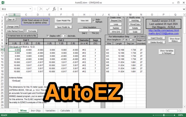 AutoEZ, Automated use of EZNEC, is an Excel workbook that works alongside EZNEC antenna modeling software version 5.0 or later. With AutoEZ, you can control different aspects of your model using variables and run multiple EZNEC test cases automatically. Formulas in Excel allow you to modify any part of the model. AutoEZ's interface resembles EZNEC's. Enabling macros in Excel might be necessary before using AutoEZ. The program opens various model file formats including EZNEC (.ez), NEC (.nec or .inp), AO and NEC/Wires (.ant), and MMANA-GAL (.maa). You can set the frequency and/or variable values for the test cases to be run through EZNEC. AutoEZ allows you to create animations showcasing how the pattern changes as the model configuration is modified. You can download a fully working, but limited demo copy from this site.
 -
 This document provides comprehensive guidance on modeling and constructing multiband dipole antennas using traps. It addresses common segmentation issues in EZNEC modeling software, recommends optimal segment lengths for trap models, and compares trapped dipoles with paralleled multiband dipoles. While trap dipoles are significantly shorter, they exhibit lower gain and narrower bandwidth. Detailed instructions for building weatherproof coaxial traps include material lists, construction steps, and tuning methods. The guide notes that properly constructed coaxial traps introduce only minimal signal loss (0.6 dB) while offering practical multiband performance in a compact design.
 -
 The article discusses the evolution of antenna designs, specifically focusing on the upgrade from the W7IUV rotatable Flag to the Waller Flag. Author Pierluigi Mansutti IV3PRK shares insights on modeling these antennas using EZNEC software, detailing their performance in noisy environments. The W7IUV Flag proved effective for receiving signals, while the Waller Flag, developed by NX4D and N4IS, offers improved front-to-back ratios but requires careful consideration of signal levels and noise management. The article emphasizes practical modeling results and interactions between different antenna setups.
 -
 This page discusses the construction and design of a shortened 2-element Yagi antenna for the 40-meter band, focusing on the driven element. The author shares insights on adding hats to the coil to reduce losses and improve performance. The article also mentions the use of EZNEC modeling software and an AIM4170 analyzer for tuning. Amateur radio operators interested in such antenna design and optimization for the 40-meter band can find useful information and practical tips on this page.
 -
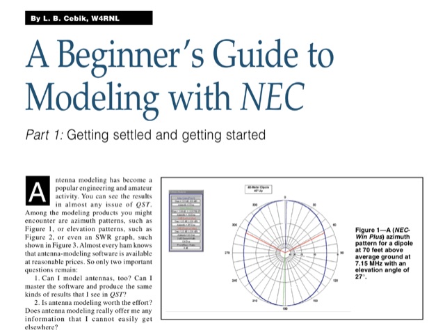 Antenna modeling is an essential technique for both amateur and professional engineers, enabling precise analysis of antenna performance. This guide, published on 4 different QST articles by L. B. Cebik, introduces NEC-2, a widely used public domain software for modeling antennas, focusing on its capabilities and practical applications. The series aims to demystify the modeling process, providing foundational knowledge and techniques for effective antenna design. Key concepts include understanding the method of moments and the importance of segmenting antenna elements. By mastering these principles, users can enhance their comprehension of antenna behavior and optimize their designs for improved performance.
 -
 This article explores the powerful features of AutoEZ as an Excel application working with EZNEC antenna modeling software. The article demonstrates how variables, equations, and formulas enable versatile antenna design and automatic optimization. Through practical examples including dipoles, inverted vees, delta loops, and monopoles, the author shows techniques for achieving resonance, implementing transmission line resonators for broadbanding, and optimizing antennas across frequency ranges. The step-by-step demonstrations cover unit conversion, coordinate calculations, segmentation considerations, and SWR optimization. This practical guide illustrates how AutoEZ extends EZNEC's capabilities, making complex antenna modeling more efficient and accessible.
 -
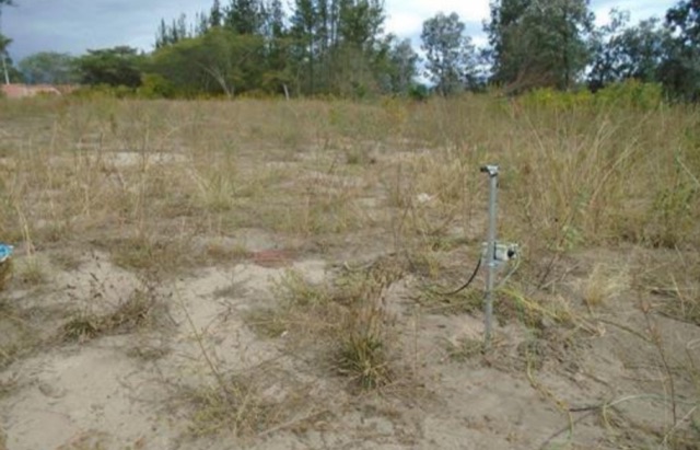 The author struggled with receiving antennas on his property. After a standard Beverage on Ground (BOG) antenna failed, he built a Reverse Beverage on Ground (RBOG) using telephone cable. He details construction and testing, finding the RBOG outperformed other antennas in noise level, signal strength, and reception pattern. Software modeling helped optimize the antenna length. Unfortunately, the project ended when telephone cable from the second RBOG was stolen.
 -
 Demonstrates the design and modeling of a **160m** vertical antenna, dubbed the "WindoVert," specifically for urban amateur radio operators with limited space. The resource covers the theoretical underpinnings of antenna height and radiation patterns, using EZNEC software to analyze current distribution and 3D radiation patterns for various configurations, including a Marconi-style "T" antenna. It details the integration of existing antenna components, such as a Carolina Windom balun and line isolator, into the new vertical setup, and the practical measurement of feedpoint impedance using an antenna analyzer. The article further explores the challenges of achieving low-angle radiation on Top Band, emphasizing the critical role of radial systems and mitigating ground loss. Author VE1ZAC presents EZNEC models illustrating the impact of lumped components and discusses the practical considerations of resonant frequency adjustment and impedance matching for **QRP** operation. The text details the calculation of required loading coil inductance and capacitance, and shares field results, including successful DX contacts on 160m and unexpected excellent performance on 30m.
 -
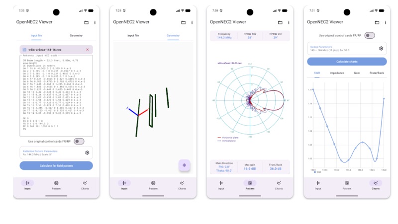 The Open NEC2 Viewer for Android provides a mobile platform for **NEC2** antenna modeling, enabling users to visualize and analyze antenna designs directly on their devices. It integrates the robust NEC2 computational library, leveraging the Method of Moments for full-wave electromagnetic analysis, and utilizes the Google Filament renderer for interactive 3D visualization of antenna structures, segmentation, and wireframes. The application facilitates the calculation of geometric parameters and antenna characteristics across specified frequency ranges. Key functionalities include parametric analysis, offering real-time computation of **radiation patterns** (RP), antenna gain, Voltage Standing Wave Ratio (VSWR), and input impedance. Users can configure flexible calculation settings to control scan step, frequency range, and various control cards, allowing for detailed electromagnetic analysis tailored to specific design requirements. Designed for radio engineers, antenna developers, radio amateurs, and students, the app is distributed as open-source software under the GNU General Public License v3.0. It provides a portable and accessible tool for electromagnetic modeling, making advanced antenna analysis capabilities available on Android devices.