Search results
Query: cb band
Links: 63 | Categories: 0
-
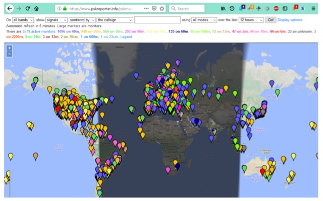 PSK Reporter,is a powerful tool for monitoring your FT8, JT65 or PSK signals around the world. But, even if you are not transmitting on any of these modes it can still be a great propagation tool for determining which bands are open and to where in the world signals from your area are being heard.
 -
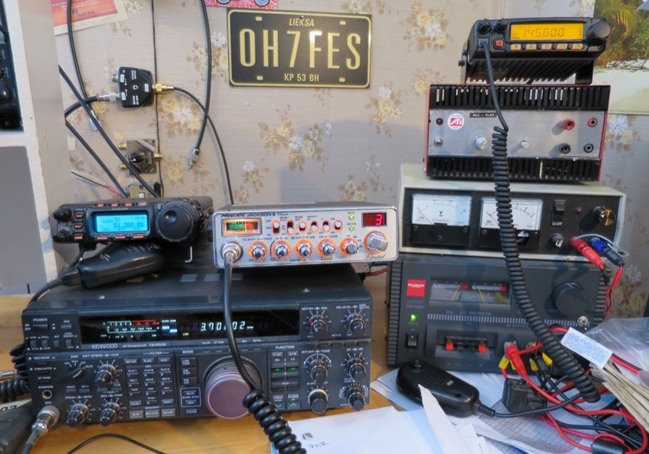 CB station AP from Lieksa Finland
 -
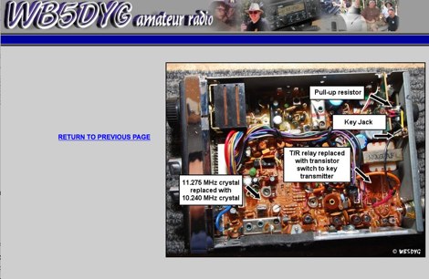 AC7GZ/B is a converted Sharp CB-2460 Citizens Band transceiver operatin on 28.2118 MHz.
 -
 The DX FT8 is a compact, multiband tablet transceiver designed for FT8 digital mode enthusiasts. Supporting five or seven HF bands, it integrates an STM32F746-based touchscreen interface for standalone operation, eliminating the need for a PC. The latest firmware (v1.9.2) adds SOTA/POTA calling and free-text messaging. Its efficient power design, unique RF amplifier, and 3D-printed case enhance portability. Open-source firmware and community-driven development make it a versatile choice for portable FT8 operation, ideal for SOTA, POTA, and travel use. DX FT8 TRANSCEIVER PROJECT is a collaboration between Charles(Charley)Hill, W5BAA and Barbaros(Barb)Asuroglu, WB2CBA.
 -
 The U01 emergency communications antenna is a versatile, multiband antenna designed for 80/60/40/20/17/15/10m bands, known for its reliability and compact size. It features a broadband transformer wound on various core options like FT82-43, FT114-43, or FT140-43, with the latter capable of handling up to 100W. The antenna incorporates a PCB with options for SMA and BNC connectors, and a weather-proofed design for durability. The lightweight construction, using materials like DX Wire UL and Polyester rope, makes it highly portable. The antenna's design has been tested and proven within the DARC Chapter U01, with multiple build options and detailed documentation available for DIY enthusiasts.
 -
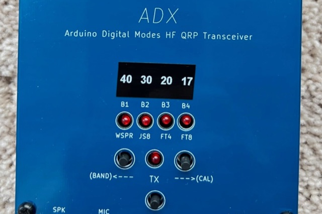 Arduino Digital Transceiver (ADX) is a low-cost HF transceiver for digital modes. This Arduino-based project, inspired by QDX, features four bands, including 80m and 20m, supporting FT8, FT4, JS8call, and WSPR. Designed for simplicity and affordability, it uses an Arduino Nano, SI5351 module, and CD2003GP receiver. The ADX project emphasizes easy procurement, construction, setup, and operation, making it an accessible option for QRP enthusiasts. The firmware update enhances functionality, including CAT control support.
 -
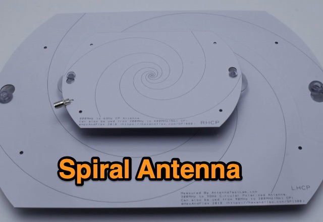 Designing and Testing a PCB Wideband Spiral Antenna. The 800 MHz+ and 300 MHz+ spiral antennas by Hexandflex
 -
 The Portable EFHW antenna for the 40, 20, 15, and 10-meter bands utilizes a broadband transformer with a 1:49 ratio, designed on a PCB by either Jan or DL2MAN. The design incorporates an **FT114 core**, offering an alternative to the FT82 core. The antenna requires precisely 20.5 meters of DX Wire Ultralight for optimal performance. Additional components include DX Wires "Dyneema" 1mm rope and 1mm bricklayers string for structural support. The SWR plot indicates performance at two elevation heights: 5.5 meters (blue line) and 4 meters (yellow line), demonstrating optimization for low-elevation portable use without poles. The antenna's components, including spool and rope tensioners, are available for 3D printing, with spool dimensions scaled to 130% for a length of approximately 110mm. The design emphasizes simplicity and portability, suitable for field deployment.
 -
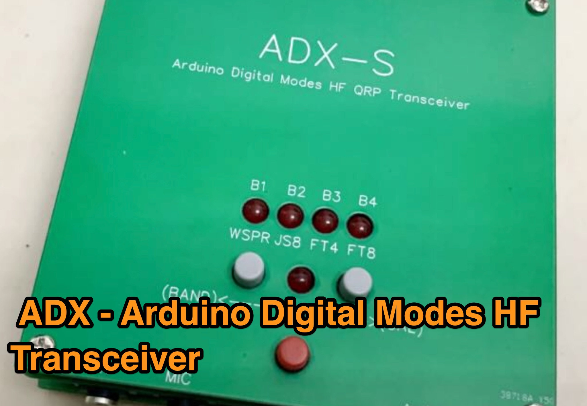 This page provides updates, manuals, and firmware for the ADX - Arduino Digital Modes HF Transceiver. Learn about calibration procedures, band display bug corrections, and important notes on the SI5351 library. The content includes a detailed build manual and firmware updates for the ADX, a mono band (actually quad band) digital modes optimized HF transceiver based on Arduino. Stay informed about the latest releases, bug fixes, and enhancements to improve your experience with the ADX transceiver.
 -
 The UV-K5 HF Fullband receive firmware version 0.3 introduces enhanced SSB capabilities using the SI4732-A10 chip. Released separately from UV-K5 CEC firmware, it offers improved HF reception, mode changes, frequency fine-tuning, and user modifications. New PCB designs and detailed usage instructions are included.
 -
 Integrating a _Software Defined Radio_ (SDR) into an existing ham radio setup involves connecting it with a standard transceiver (TRX), power amplifier (PA), and antennas. The core component is a splitter box that facilitates the connection between the TRX and the SDR, allowing for simultaneous operation without modifying existing equipment. In receive mode, the splitter ties the antenna inputs of both the TRX and a direct conversion receiver (DC RX) together. During transmission, the DC RX input is grounded via a fast telecom relay controlled by the transceiver's -SEND signal, incorporating a 10ms delay for safety. The splitter box includes a 3.7 dB input attenuator for impedance matching and acts as a protective fuse for the DC RX input. Ground loops are mitigated using common mode balun transformers, while the DC RX input is insulated with a broadband transformer. An audio switch box complements the setup, enabling users to listen to either the main transceiver, the SDR output, or both simultaneously. This configuration ensures noise immunity and safety, with the splitter housed in a screened box made from PCB material. On-air tests, such as the CQ WW 160m CW DX Contest, demonstrate the system's effectiveness, showcasing the SDR's ability to handle crowded band conditions with superior selectivity and dynamic range. The SDR's narrow bandwidth filters and waterfall display provide significant advantages, allowing operators to detect weak signals amidst strong interference. The integration of SDR with conventional radios offers enhanced operational flexibility and performance in challenging environments.
 -
 This article explores the powerful features of AutoEZ as an Excel application working with EZNEC antenna modeling software. The article demonstrates how variables, equations, and formulas enable versatile antenna design and automatic optimization. Through practical examples including dipoles, inverted vees, delta loops, and monopoles, the author shows techniques for achieving resonance, implementing transmission line resonators for broadbanding, and optimizing antennas across frequency ranges. The step-by-step demonstrations cover unit conversion, coordinate calculations, segmentation considerations, and SWR optimization. This practical guide illustrates how AutoEZ extends EZNEC's capabilities, making complex antenna modeling more efficient and accessible.
 -
 Radio classifieds, technical articles, reviews and antenna designs for CB and Amateur bands.