Search results
Query: oscillator
Links: 84 | Categories: 1
Categories
-
 Schematic diagram of a two tone audio oscillator by VK3YE
 -
 Quartslab has over 30 years of experience in supplying quartz crystals to the international communications market. Our product range includes the supply of quartz crystals in the frequency range 1.5 to 225 MHz in all popular holder types as well as crystal oscillators in DIL8 and DIL14 packages.
 -
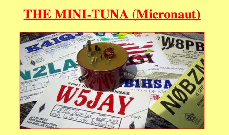 A simple transmitter built into a small cat-food tin! It consists of a single 2N2222 crystal oscillator and runs about 100mw output, depending on the supplied voltage
 -
 The San Bernardino Microwave Society, operating under the callsign _W6IFE_, serves as a significant technical hub for amateur radio operators specializing in frequencies above 1 GHz. This organization's influence extends across Southern California, providing a centralized resource for advanced RF experimentation and **regional frequency management** within the microwave spectrum. Its permanent value lies in its extensive archive of technical papers and project documentation, which are critical for operators engaged in high-frequency design and deployment. The society's infrastructure is primarily intellectual, focusing on the dissemination of specialized knowledge rather than a conventional repeater network. It offers a robust collection of technical papers from prominent members like K6PIP, K6BLG, and WA6EXV, covering topics such as Rubidium oscillator data, logging software, and filter design. This resource facilitates advanced amateur radio operations, including participation in microwave contests and the development of custom transverters for bands like 24 GHz. The site also details various member projects, such as the Owens Valley Radio Observatory Project, showcasing practical applications of **RF propagation analysis** and system integration. DXZone Focus: Microwave | Technical Papers | RF Propagation | Contest Results
 -
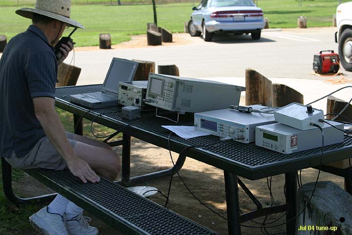
 Designed for portable operation, it runs on 12v, and has an OCXO-based local oscillator.
 -
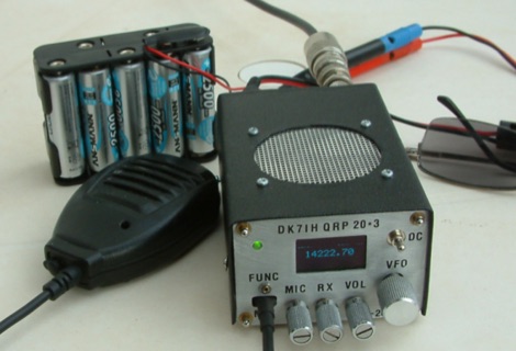 DK7IH QRP transceiver for 14 MHz. This small and compact home made transceiver with a max power output of 5W, the VFO module is based on the clock oscillator chip Si5351A by Silicon Labs ATmega168 and OLED 1306
 -
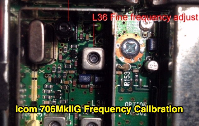 Unlike older radios, the 706 uses only one crystal oscillator (called the Master Oscillator). All other frequencies in the radio (L.O., 3-4 I.F. stages, VFO, and CW-offset) are computer-derived from the Master Oscillator. This makes it relatively simple to frequency-align the radio, so that it agrees with the Frequency Display in all modes.
 -
 Clarifies the intricate process of calibrating the _Elecraft K2_ dial, addressing common user challenges and lively discussions on the Elecraft reflector. Wilhelm, W3FPR, dissects the K2's PLL synthesizer design, chosen for its low phase noise, kit-friendly duplication, and cost-effective components. The resource emphasizes the critical role of the 4000.000 kHz reference oscillator's accuracy during CAL PLL, CAL FIL, and CAL FCTR functions, noting its dependence on temperature and crystal stability for optimal performance. Explaining the K2's frequency display, the document reveals it relies on microprocessor-driven look-up tables generated by CAL PLL for VFO values and CAL FIL for BFO values. In SSB and RTTY, these combine, while CW and CWr modes also factor in the sidetone pitch. The author details inherent limitations, such as the 10 Hz increment resolution of the dial and varying PLL step sizes—from 3 Hz on 160 meters to 10 Hz on 10 meters. BFO increments range from 20 to 35 Hz, collectively limiting practical dial accuracy to within **20 Hz** with diligent effort, or **30 Hz** for a slightly less demanding task. The guide outlines a four-step calibration procedure: setting the reference oscillator, running CAL PLL, running CAL FIL, and setting all BFOs. It highlights the _N6KR Method_ as a particularly easy and accurate approach, requiring only the K2 and a known frequency source like WWV for zero-beating, eliminating the need for external test equipment.
 -
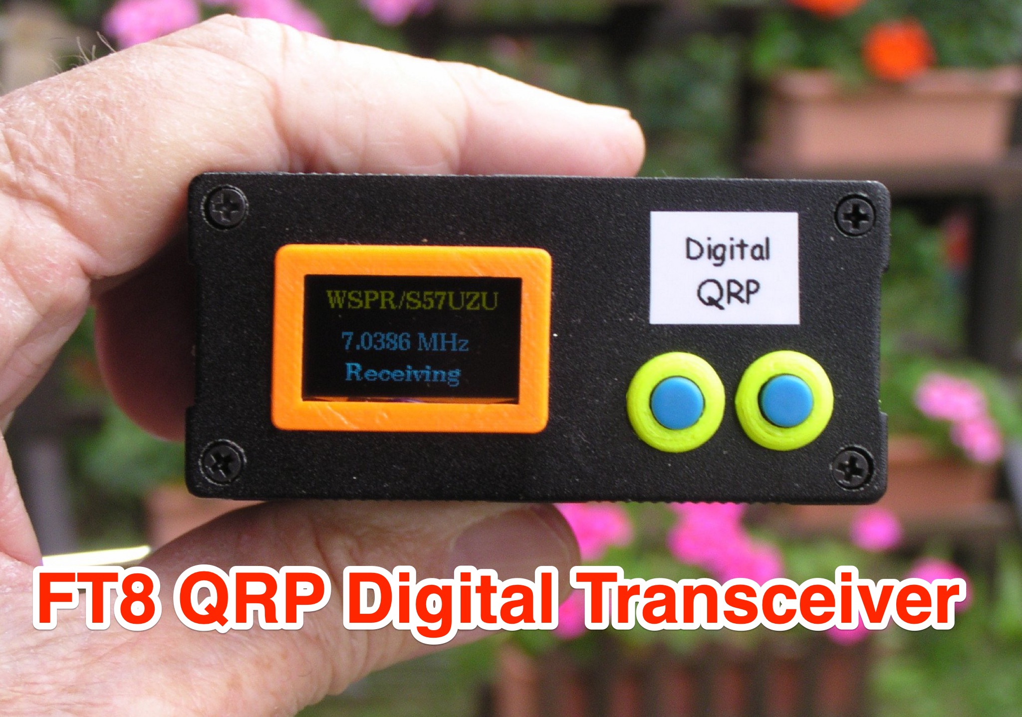 Learn how to build a QRP digital transceiver with Arduino, based on a project by Burkhard Kainka. This article covers the development process, including the source code, modifications made, and the addition of an OLED display for a more professional look. Discover the inner workings of the transceiver, from the receiver to the oscillator, and how components like the CD2003 are utilized. Explore the schematic design, the use of a PLL module Si5351A controlled by Arduino nano, and more. Ideal for hams looking to create their own digital transceiver for amateur radio operations.
 -
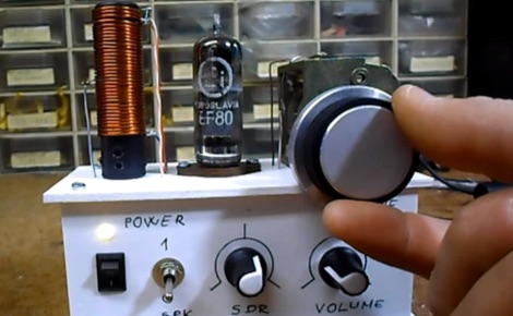 The build was an experiment to see if a tube receiver could be stable enough to receive digital shortwave radio broadcasts. The tube acts as both an oscillator and mixer, so the receiver is a type of direct conversion receiver.
 -
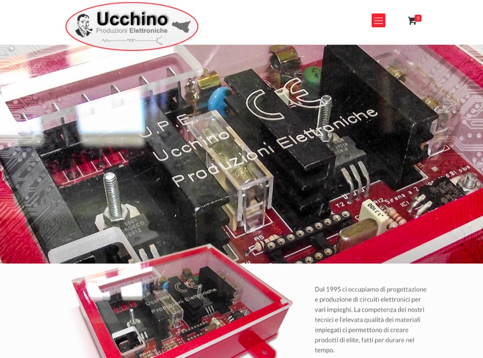 Ucchino is an Italian manufacturer of electronic cirucits inclunding Digiham amateur radio USB interface for digital modes, morse code oscillator, filters and RF protectors
 -
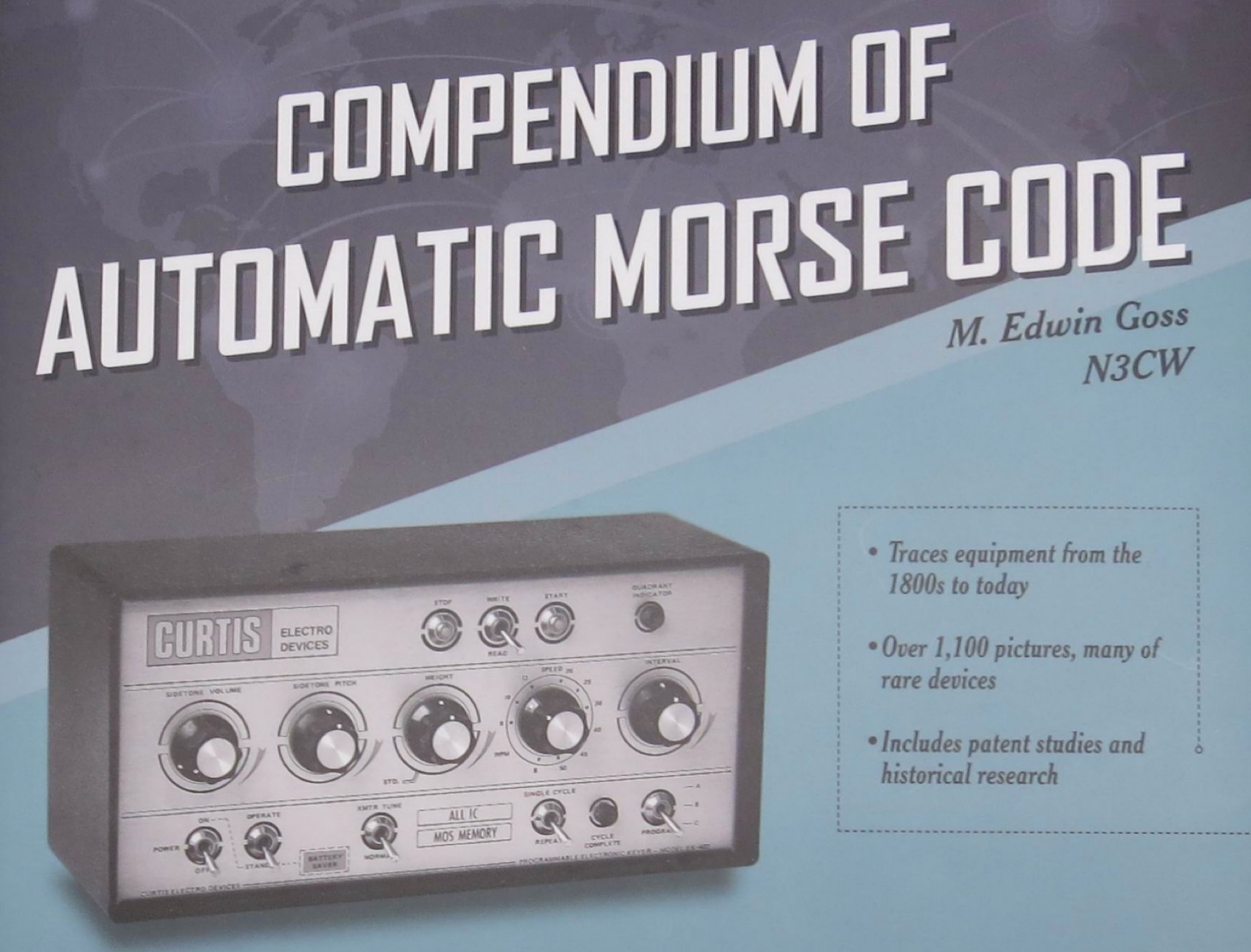 Book on CW paddles, history of keyers, keyboards, oscillators, and all things related to automatic Morse code.
 -
 The video showcases the setup of a 300 MHz oscillator, a 100W radiofrequency amplifier, and a dipole antenna for transmitting radio waves, leading to the fluorescence of a nearby light bulb. It demonstrates the presence of standing waves on the dipole antenna and how intensity varies along its length. Additionally, the usage of a copper pipe as a receiving antenna is explored, showing changes in intensity depending on alignment and proximity to the transmitter. Finally, a B field antenna sensitive to magnetic fields is introduced, revealing brightness variations in different orientations. The video offers insightful observations on radio wave transmission and reception phenomena.
 -
 A simple superheterodyne receiver (3.5–30 MHz) for amateur radio achieves stable SSB-CW reception using modern BJTs, an AD831 mixer, a 6-pole quartz filter, and Seiler oscillators. Designed with high IF (4.5 MHz), compact AM-FM variable capacitors, and modular resonant circuits, it ensures selectivity, image rejection, and stable tuning. Built in a copper-lined wooden case, it features practical assembly techniques but lacks advanced features like AGC or S-meter. Effective on basic antennas, it achieves global reception.
 -
 Web site and blog that reviews equipment, goes over safety, and display projects being built. Includes Yaesu FT-891 and Ameritron RCS-10 Review, a 555 Morse Code Practice Oscillator, and and arduino based Morse Code Practice Oscillator
 -
 The 222 MHz Transverter project, based on Zack Lau's (W1VT) original July 1993 QEX magazine design, provides an IF of 28 MHz for both transmit and receive paths. Rick Bandla (VE3CVG) contributed supplemental notes and construction details, including modifications to achieve 10 mW output power from an initial 4 mW PEP. The design incorporates three distinct boards: a Local Oscillator (LO), a Transmitter (Tx), and a Receiver (Rx), with an estimated parts cost of just over $150 CDN, significantly less than commercial kits. Construction involves both through-hole and surface-mount components, with specific guidance on mounting MAV and MAR devices, grounding techniques, and component selection. The project details include parts lists, schematics for the LO, Tx, and Rx, and board layouts. Troubleshooting advice emphasizes sequential testing, starting with the LO, then Tx, and finally Rx, using a 194 MHz and 222.100 MHz capable FM handheld for signal tracing. Further enhancements are discussed, such as an optional Tx driver stage to boost output to 100 mW and the potential modification of a Motorola Maxor 80 PA for 222 MHz SSB/CW operation. The resource also covers practical aspects like power attenuation pads for IF radios (e.g., FT817) and considerations for enclosure design, including repurposing a Maxor 80 case. Performance reports indicate successful 70 km contacts with only 4 mW output.
 -
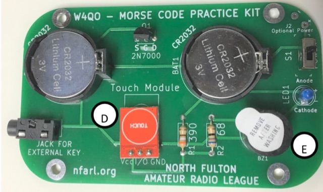 The Code Practice Oscillator kit, featured at TechFest 2020, provides a straightforward device for Morse Code skill development. It utilizes two 3V coin batteries for power and is designed for ease of construction, making it accessible for hams of various ages. The kit's primary technical substance revolves around generating an audible tone for practicing Morse Code timing and ear training, with a downloadable schematic detailing its electronic configuration. Construction of the oscillator involves soldering, with adult supervision recommended for younger builders. The kit's practical application lies in offering a hands-on method for beginners to learn Morse Code and for experienced operators to refine their sending abilities. Instructions for assembly are available as a downloadable PDF, complementing the schematic to guide users through the building process.
 -
 The Specan is actually a very simple but robustly built receiver. it is, in essence, a double conversion superhet receiver with 112 Mhz and 12 Mhz Intermediate frequencies. The first mixer uses an Si570 as the local oscillator. The Ardiuno that controls the Specan is a very flexible microcontroller board that you can program in simple C language
 -
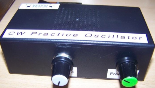 This project builds into a box into which you plug a Morse Code Key. Using the Morse Key creates realistic sounds so you can judge how well you Send. A great tool for beginners to improve Morse sending skills before going on-air
 -
 Kanga Products offers a diverse range of kits and pre-built items for amateur radio operators, including Morse tutors, keys, antenna tuners, and dummy loads. Their products cater to both beginners and advanced users, with options for practice oscillators, receivers, and various electronic components. The company provides detailed instructions and supports DIY projects, making it a go-to for hobbyists seeking practical and educational tools.
 -
 This article describes an HF upconverter for the FunCube Dongle Pro. Designed for radio amateurs, the converter extends reception capabilities to lower frequencies (0 Hz to 30 MHz) by mixing them with a higher oscillator frequency (100 MHz). This translates the desired signal into a range detectable by the FunCube Dongle (64 to 1,700 MHz). Key components include a double-balanced mixer and a low-pass filter to suppress unwanted signals. The project provides schematics, filter specifications, and design considerations for construction.
 -
 Recently, at the Ballarat Hamfest, the author acquired an old Marine transceiver for just $10, charmed by its sturdy construction and waterproofing. Made by Findlay Communications in Sydney, this crystal-controlled transceiver had been dormant but was reinvigorated with minor fixes. A manual was sourced, and further repairs were made, including an ingenious crystal oscillator replacement using an Si5351a controlled by an Arduino. The refurbished radio, complete with a fresh coat of paint and added customizations, is now operational for 160m AM and 30m SSB. A successful and cost-effective restoration.
 -
 This project details the development of a modular direct conversion (DC) receiver designed for experimental flexibility in amateur radio and HF signal listening. The mainframe integrates a diplexer, DBM, and AF amplifier, supporting interchangeable local oscillator and antenna filtering setups. A tunable passive HF preselector complements QRP Labs bandpass filters for enhanced signal reception. Utilizing a NanoVNA for precise tuning, the receiver achieves improved signal-to-noise ratios across amateur and non-amateur bands, making it a versatile platform for further RF experimentation.
 -
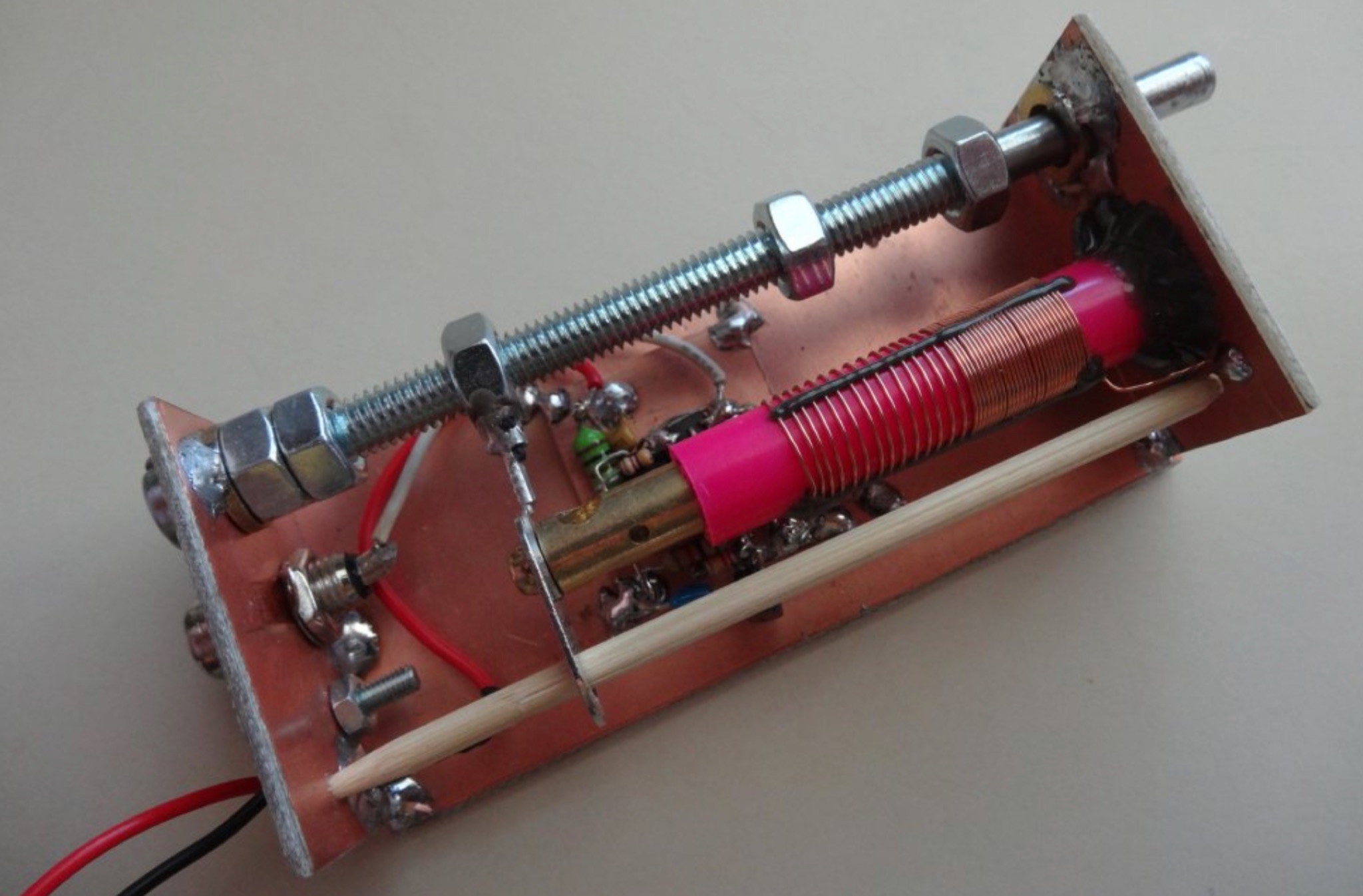 Learn about Permeability Tuned Oscillators (PTO) and why they are useful for ham radio operators. This page covers the mechanics of PTO tuning, the components involved, and how to wind the PTO inductor. Written by Andrew Woodfield ZL2PD, this resource provides a detailed guide for building and using a PTO oscillator in your amateur radio projects.
 -
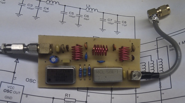
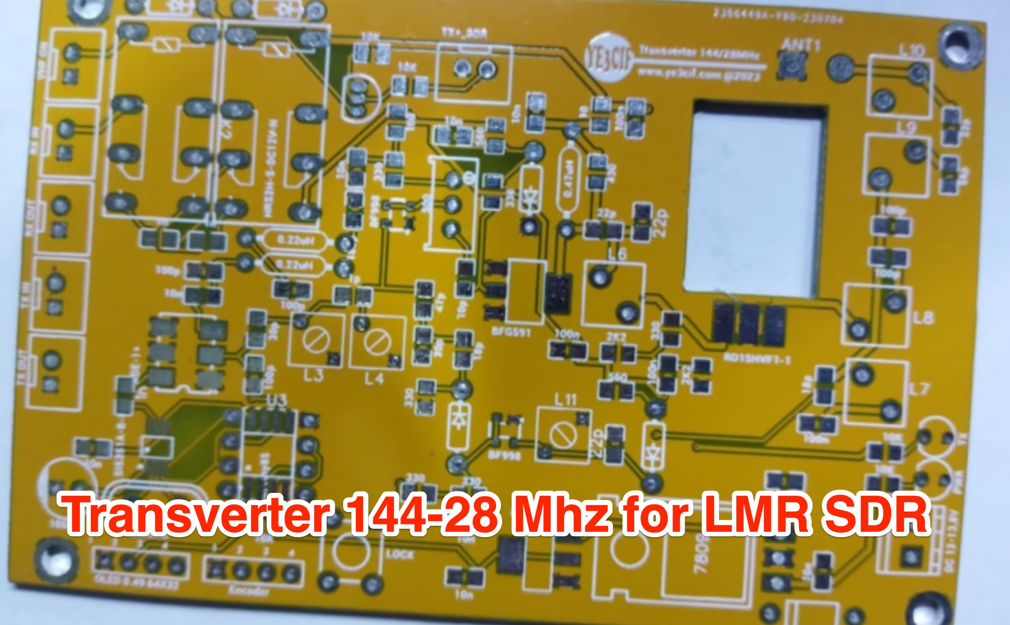 Learn how to build a VHF 144MHz transverter connected to an LMR SDR radio using easily accessible components. The transverter works by mixing the 144Mhz input frequency with a 116 MHz local oscillator frequency. Explore the challenges of finding a 116 MHz crystal and the solution of using a programmable Si5351A oscillator. Follow the provided schematic for the RX and TX sections. The transverter design is still a work in progress, with ongoing trials to achieve optimal results.
 -
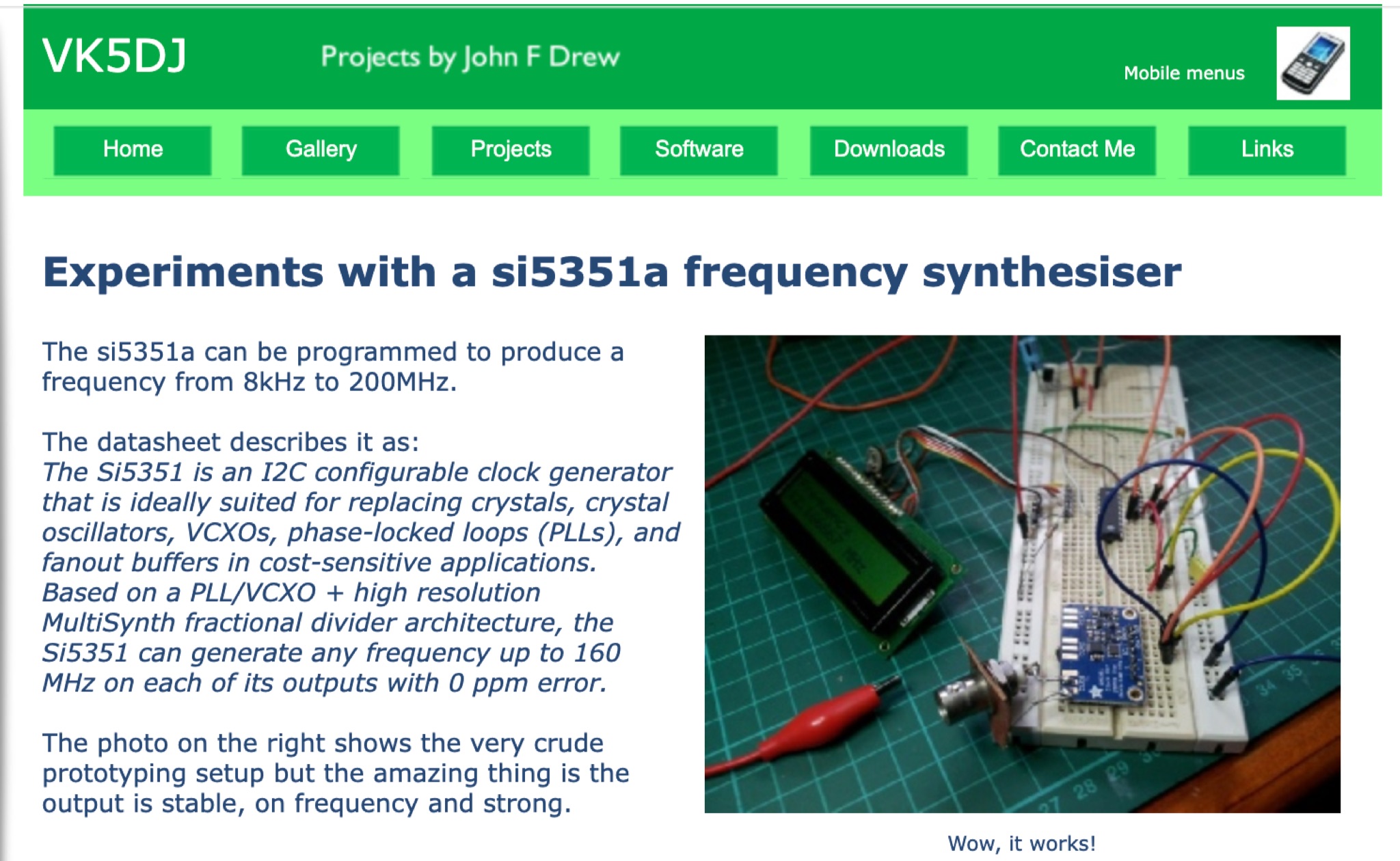 Explore VK5DJ's experiments with the si5351a frequency synthesizer, a versatile device capable of generating frequencies from 8kHz to 200MHz. Learn how this I2C configurable clock generator can replace crystals and oscillators in various applications, providing stable and precise outputs. Discover how to program the si5351a for your own signal generator projects and repeater site setups. Utilize the affordable and efficient Adafruit module for reliable performance. Enhance your understanding of PLL/VCXO architectures and fractional dividers for frequency generation. Join the PDS Forum community in experimenting with this innovative technology.
 -
 A versatile digital VFO design utilizing the Silicon Labs Si5351a oscillator chip and Nokia 5110/3310 graphics LCD display, operating from 1-160MHz with dual VFO capability. This microcontroller-based system, powered by an ATmega328 processor, features rotary encoder tuning, selectable step sizes, RIT control, and comprehensive band memory functions. Drawing less than 40mA at 3.3V, it significantly improves upon previous DDS designs' power consumption while offering advanced features like S-meter display, VFO lock, and programmable BFO/CIO offsets. The design achieves flexible functionality through simple hardware implementation and efficient software architecture, making it particularly suitable for QRP and portable amateur radio applications.
 -
 The YIG Tuned Oscillator (YTO) is the only direct signal source to provide multi octave tuning bandwidths in excess of 10 GHz. Common tuning ranges are from 2-10 GHz, 8-18 GHz and 10-20 GHz. YTO is are also known for their superior phase noise and exceptional tuning linearity.
 -
 This resource presents a non-rigorous evaluation of the front-to-back (F/B) ratio of short Beverage antennas, specifically designed for low-band operation on frequencies such as 160, 80, 40, and 30 meters. The author, VE1ZAC, details the methodology used to measure the F/B ratio, which involves using a Millen Grid Dip Oscillator as a portable signal source. Measurements were taken by switching the antenna direction and recording S Meter and preamp readings to derive gain numbers. The document discusses the challenges faced in achieving accurate measurements and the assumptions made during the process, such as the calibration of S Meter units at 6 dB. This evaluation is particularly relevant for amateur radio operators interested in antenna performance on low bands.
 -
 The project details the construction of a GM3OXX OXO transmitter, designed to accommodate **FT-243 crystals** using 3D-printed FX-243 holders from John KC9ON. It presents specific frequency adjustments, noting a 7030 KHz HC-49/s crystal could be tuned from 7029.8 KHz to 7031.7 KHz with an internal 45pF trimmer capacitor. The build incorporates a modified keying circuit to prevent oscillator run-on key-up and includes a TX/RX switch for sidetone via a connected receiver, with the transmitter output routed to a dummy load on receive. Practical construction aspects are thoroughly covered, including the process of cutting a rectangular opening in a diecast enclosure for the FT-243 socket and the selection of a **low-pass filter** (LPF) based on the QRP Labs kit, derived from the W3NQN design. The author achieved approximately 800mW output power from a 14.75V supply, measured with an NM0S QRPoMeter, using a 16.5-ohm emitter resistor in the 2N3866 final stage. The article also touches upon the potential for frequency agility across the 40M band using multiple FX-243 units with various crystals. The narrative includes a brief diversion into Bob W3BBO's recent homebrew projects, such as his Ugly Weekender MK II transceiver, highlighting the enduring appeal of classic QRP designs. The author reflects on the personal satisfaction derived from building RF-generating equipment, irrespective of DX achievements, and shares experiences of making local contacts with the 800mW OXO transmitter on 40 meters.
 -
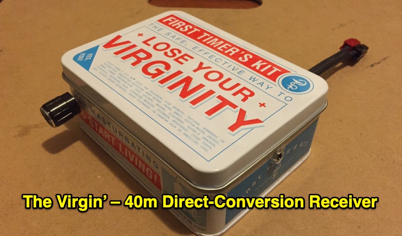 Demonstrates the construction of 'The Virgin', a **direct-conversion receiver** specifically designed for the 40m amateur radio band. This project, completed in February 2016, features a fixed operating frequency determined by a crystal oscillator, requiring a physical crystal change to alter the reception frequency. The design incorporates two integrated circuits and a power regulator, emphasizing simplicity with a single control knob. The author details the initial design, subsequent modifications to the front end, and troubleshooting steps addressing common issues like audio motorboating and power supply instability. The resource presents the final design of the receiver, reflecting the author's first experience building such a unit between December 2015 and February 2016. It offers practical insights into basic circuit construction and the iterative process of refining a homebrew radio project. The content is particularly relevant for those interested in fundamental receiver principles and hands-on **QRP** transceiver building.
 -
 Demonstrates the construction of an active loop converter specifically designed for the Low Frequency (LF) bands, addressing common localized noise interference in LF reception. The design integrates a sharply tuned circuit and a tuned loop antenna, utilizing the loop as the sole tuned inductive element. By applying positive feedback, the converter significantly increases the loop's effective Q, achieving factors between 1000 and 2000, which sharpens tuning and reduces noise. The circuit employs an _NE602_ mixer stage, feeding its output to an HF receiver, with a crystal-locked local oscillator at 4 MHz. A 20-turn, 0.8-meter square loop antenna with 500 uH inductance is detailed, connected via 2 meters of figure 8 flex cable. The converter offers three selectable frequency bands: 195-490 kHz, 150-220 kHz (including the New Zealand amateur band), and 128-160 kHz (covering the European amateur band). Performance measurements indicate an effective 3dB bandwidth of approximately 100 to 200 hertz at 200 kHz. The article provides insights into component selection, including an _LF353_ op-amp and a trifilar wound transformer on a ferrite core. Sensitivity figures are presented, showing 7.5 uV of converted output per 1 uV/meter signal strength into a 50-ohm load, or 37.5 uV into an _FRG7_ receiver, highlighting its capability to extract weak signals from noise.
 -
 The W6PQL 23cm Beacon Project describes a **1296 MHz** beacon designed for microwave propagation studies and equipment testing, capable of 30 watts output. It utilizes a PIC 16F628A microcontroller to generate CW and FSK keying for a crystal oscillator, followed by a series of frequency doublers and triplers to reach the target frequency. The final power amplification stage employs a Mitsubishi M57762 module, providing a robust 10-watt RF output. The design emphasizes stability and reliability for continuous operation, with the microcontroller code, written in assembly, provided for customization of the beacon's callsign and message. Originally located in CM97am and aimed at 140 true, the beacon used four 4-foot Yagis stacked vertically for a total ERP of 3kW. The article includes schematics, parts lists, and construction notes to guide builders, along with antenna pattern measurements. Although the beacon itself is no longer in service as of August 2010, the detailed documentation remains a valuable reference for amateur radio operators interested in building similar **microwave** projects or understanding beacon operation.
 -
 This online construction guide details the assembly of a signal generator specifically for the **13cm band** (2.4 GHz). The curriculum focuses on the integration of a Voltage Controlled Oscillator (VCO), specifically the ROS-2400, to produce a stable RF signal. The resource outlines the necessary components for frequency generation and output, including the use of a Mini-Circuits MMIC amplifier for signal conditioning. The construction protocol involves configuring the ROS-2400 VCO to operate within the 2.3 GHz to 2.45 GHz range, ensuring frequency coverage for amateur radio _microwave experimentation_. The guide specifies the output power level, approximately 70mW, directly from the MMIC stage, indicating its application as a low-power instrumentation source rather than a transmit-capable device. This project provides a practical example of constructing a dedicated test instrument for microwave frequency measurements and system alignment on the **13cm band**. DXZone Focus: Construction Guide | 13cm Signal Generator | VCO Integration | Microwave Experimentation