Search results
Query: photos
Links: 83 | Categories: 1
Categories
-

-
 Funny photos of IQ7R contest team and dx-spedition
 -
 Kingsport Amateur Radio Club / Bays Mountain Radio Club , Serving Tri-Cities TN/VA Area, Useful Technical Links, Club Photos
 -
 A free photo hosting service for amateur radio. Upload your own photos or browse through what others have uploaded.
 -
 Information about Venezuela, frequencies, maps, photos, history, and related links
 -
 Activities, legal infos, technical articles, photos, vendors, software, and links
 -
 Personal page with photos and info on used equipment
 -
 Personal page with meeting photos and eleven meter maps too
 -
 Reportage of the CQWW CW contest in 1998, with full history of the event and photos of equipment used.
 -
 RUSSIA Ham radio club AMUR, FarEast Khabarovsk. News, events, photos.
 -

-

-
 Features an immense gallery of color photos, facts, newsletters, articles and links for those interested in collecting or restoring antique radios
 -
-
 QSL Cards design and printing, offer free shipping and free graphic design from any quantity of photos and graphics
 -
 Demonstrates the construction of a high-power 6-meter (50 MHz) amplifier, specifically designed for demanding modes like EME, TEP, and multiskip Es. It details the use of a _GU-43B_ tetrode in a grounded-cathode configuration, emphasizing the need for stabilized grid voltage and input capacitance compensation. The resource provides a comprehensive schematic, power supply design, and practical considerations for component sourcing, particularly for high-voltage and high-current sections. The builder achieved an output power of **1250 watts** with an anode current of 0.65 amperes and 3200 volts anode voltage. The article also covers the physical construction within a modified P6-31 enclosure, outlining the internal layout for RF and power supply sections, and includes photos of the completed unit. It highlights critical safety precautions for working with high voltages and reactive currents up to **20 Amperes** in the P-network.
 -
 A 0-30 MHz step attenuator, constructed from switchable Pi attenuation pads, provides a practical tool for evaluating receiver sensitivity and calibrating S-meters. The design utilizes readily available 5% tolerance resistors, with values derived from paralleled components to achieve specific attenuation steps. A schematic (Fig 1) illustrates the circuit, including PCB pad shielding, while a table details required and actual resistor values, along with percentage differences. Measurements of voltage input versus output at various frequencies are used to calculate dB attenuation, presented in a graph (Fig 4). The resource includes formulas for determining output voltage from a known input and a comprehensive 0-40 dB voltage multiplier table, which is crucial for precise signal level management. The project also references external attenuator calculators and equations for further study. Photos (1-3) provide visual guidance for the assembled unit, showing bottom, top, and front views. The project emphasizes the use of **Pi attenuation pads** and **receiver sensitivity** evaluation, offering a hands-on approach to RF signal management.
 -
 The W6JWS 2-meter Repeater Maintenance and Repair Log documents the ongoing upkeep of a 146.745 MHz repeater, specifically addressing modifications to enhance its functionality. It details changes made to ensure the repeater powers up in _PL mode_ and to improve the reliability of touch-tone control, drawing comparisons to similar work performed on the AE6KE repeater. The log also notes a repair to a fused wire in the reverse battery protection circuit after an accidental polarity reversal, highlighting a temporary workaround where a wire was omitted but the system remained operational. The resource includes practical insights from Jeff Liebermann, AE6KS, regarding jumper configurations and programming, with accompanying photos. It provides access to several documents for the Icom RP-1510 repeater, including operating manuals and a schematic for the single logic board version, which differs from the dual-board configuration described in some printed manuals. The log mentions a specific modification to adjust the dropout delay, which was later deemed unnecessary, and references a related project for the AE6KE repeater, aiming to replicate successful modifications on the W6JWS machine, resulting in improved touch-tone reliability and proper PL mode activation.
 -
 The Buddistick antenna, as demonstrated by KP4MD, effectively handles up to **250 watts** and provides coverage from 40 through 10 meters, with an optional coil extending operation to 80 and 60 meters. KP4MD's video presentation meticulously describes the antenna setup, emphasizing the critical role of the _shunting coil_ for achieving resonance on lower bands like 40 and 80 meters. This practical approach highlights how a compact antenna can deliver solid performance from a constrained location. SWR curve diagrams are included, clearly illustrating the impact of the shunting coil on the antenna's resonating frequency. These visual aids provide concrete evidence of the adjustments needed for optimal operation across different bands, particularly when space is at a premium. KP4MD's insights are particularly valuable for hams operating from apartments or other limited spaces, showcasing real-world results from a balcony installation.
 -
 Hamradio links and D-star and photos from Sweden and Europe.
 -
 Personal Page UR4IOR from Ukraine, with some nice personal photos.
 -
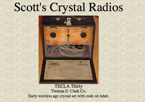 The TECLA Thirty, an early wireless age crystal set, is featured among a gallery of over 100 collectible headphones, with detailed close-up photos of vintage models. Several pages offer vintage headphones for sale, including Brandes, Baldwin, and Western Electric, suitable for crystal set use or collecting. Construction details are provided for a reproduction KILBOURNE AND CLARKE crystal set, built with vintage 1920s parts and featuring a miniature variable condenser for fine tuning. The resource also presents a project for a simple crystal radio and a 1-tube amplifier, complete with a schematic and component diagram, suitable for driving a horn speaker or amplifying weak signals for headphones. Instructions for mounting argentiferous galena detector crystals are included, along with information on MRL Handbooks covering crystal detectors and modern diodes. Additional projects include a 2A3 single-ended triode tube amplifier and two stereo tube amps using 12AX7, 6V6, 5Y3G, 6SN7, VT-25, and 5U4G tubes.
 -
 OK2ZC ex ok2bee homepage with log search and photos
 -
 SV1GRB's Homepage, photos from dx-peditions and useful links
 -
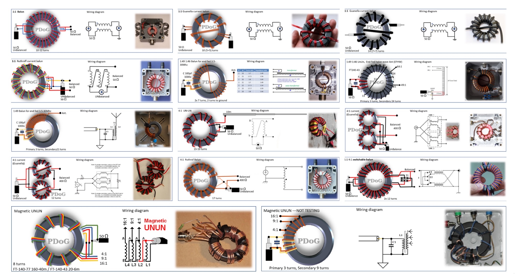 This page provides a detailed guide on the Guanella Current Balun for ham radio operators. The author shares very nice schematics, photos, and explanations on the construction and use of this type of balun. The content explains when a balun is needed and how it can help with common-mode currents in antenna systems. It also discusses the construction process, including winding the balun around a ferrite core. This resource is useful for hams looking to improve their antenna systems and reduce common-mode currents for better performance. This article is in Dutch.
 -
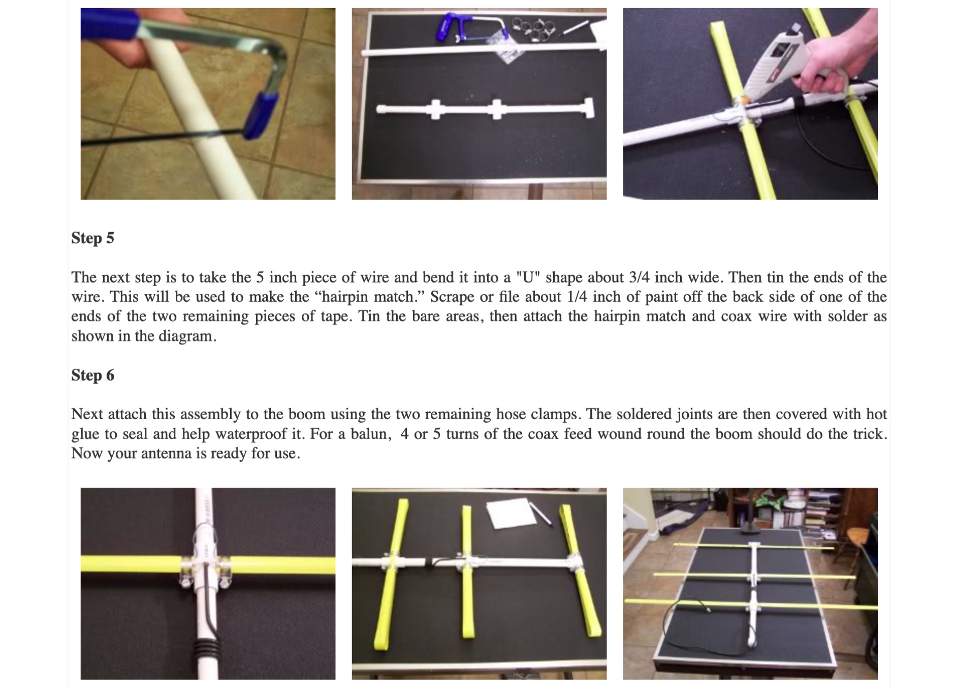 Wireless Society of Southern Maine Projects, instructions and photos for many ham radio projects and experiments, including antenna construction and modelling, kit building, station setup, restoration and more
 -
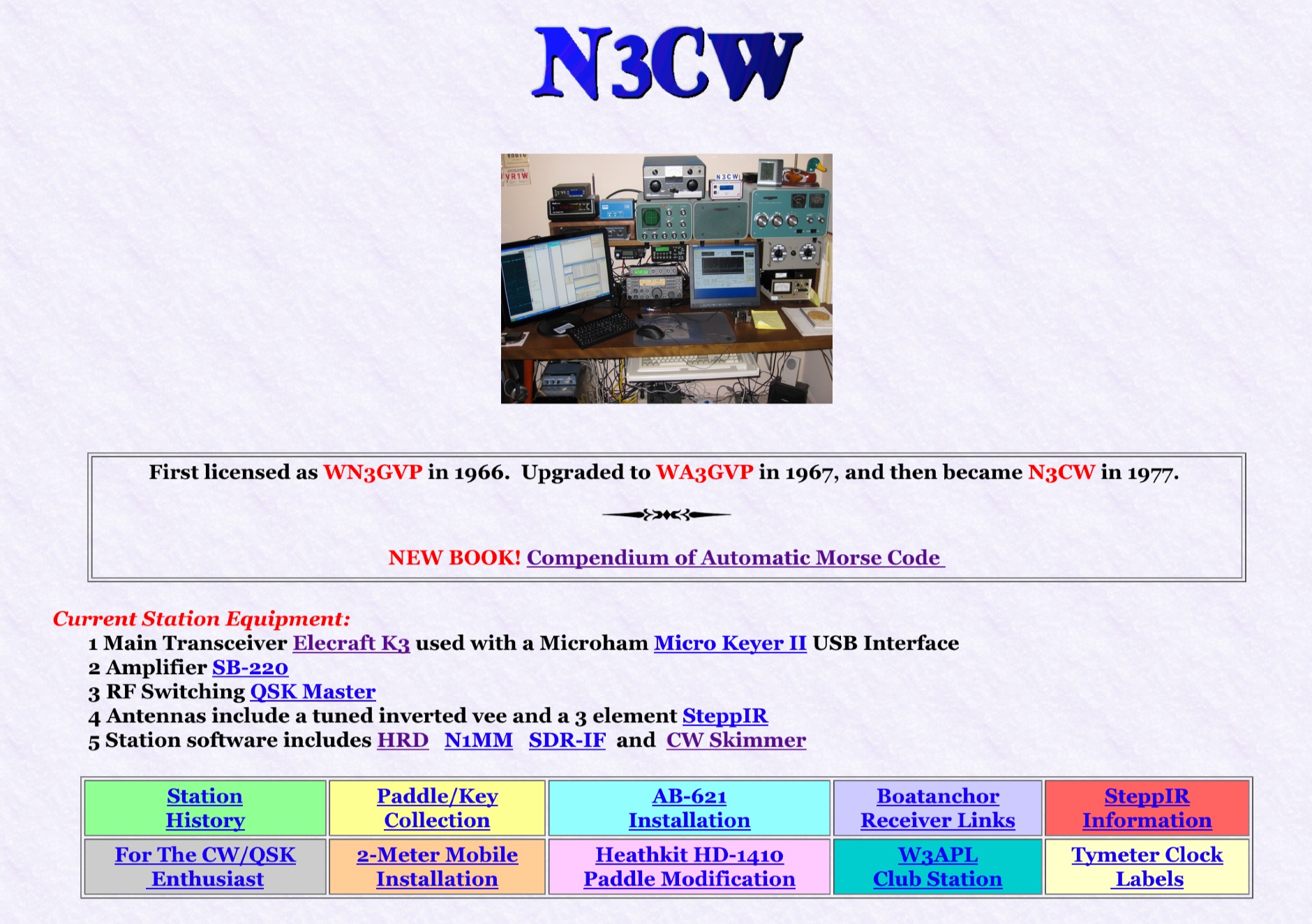 Station information, Morse CW information, antenna photos
 -
 Building an End-Fed Half-Wave (EFHW) antenna from a kit, as detailed by Frank Bontenbal, PA2DKW, with process photos by Bob Inderbitzen, NQ1R, offers a practical approach for hams. This specific kit, a collaboration between ARRL and HF Kits, targets 10, 15, 20, and 40 meters, making it a versatile option for HF operations. Unlike a center-fed dipole, the EFHW is a half-wavelength antenna fed at one end, which simplifies deployment, particularly for portable use. The construction guide meticulously outlines the assembly of the 49:1 impedance matching network, crucial for transforming the antenna's high impedance (around 2,500 Ohms) to a transceiver-friendly 50 Ohms. Steps include preparing the enclosure by drilling holes for the coaxial connector and antenna connections, followed by the precise winding of enameled copper wire onto a toroid to create the transformer. The guide emphasizes careful insulation removal and soldering for reliable connections. Final assembly involves integrating a 100 pF capacitor for higher band compensation, soldering the transformer's primary and secondary sides, and conducting SWR tests with a 2K7 resistor or a half-wavelength wire. The document also provides examples of wire lengths for different bands, such as 16 feet for 10 meters or 66 feet for 40 meters, demonstrating the transformer's adaptability for various half-wavelength configurations.
 -
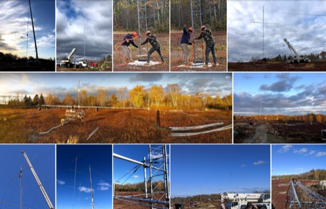 Photo gallery of a work of several weeks consisting of the construction of 5 towers and 28 antennas at the new Jonesport, ME station.
 -
 A coaxial cable trap is a fundamental component in multiband antenna design, enabling a single radiator to resonate efficiently on multiple frequencies by electrically shortening or lengthening the antenna element. This project focuses on constructing such a trap for a vertical antenna operating on the 10 MHz (30m) and 14 MHz (20m) amateur bands, providing practical insights into its fabrication and integration. The article outlines the specific dimensions and winding techniques for the coaxial trap, emphasizing the use of readily available materials. It details the physical construction of the vertical element, including the mast and radiating sections, to achieve optimal performance across both target bands. The author shares personal experiences with similar trap designs, noting their effectiveness in previous horizontal dipole configurations. Key construction steps are illustrated with _original photos_, showing the assembly of the trap and its incorporation into the overall antenna structure. The design aims for a compact footprint, making it suitable for limited space installations while still delivering effective DX capabilities on the **30-meter** and **20-meter** bands.
 -
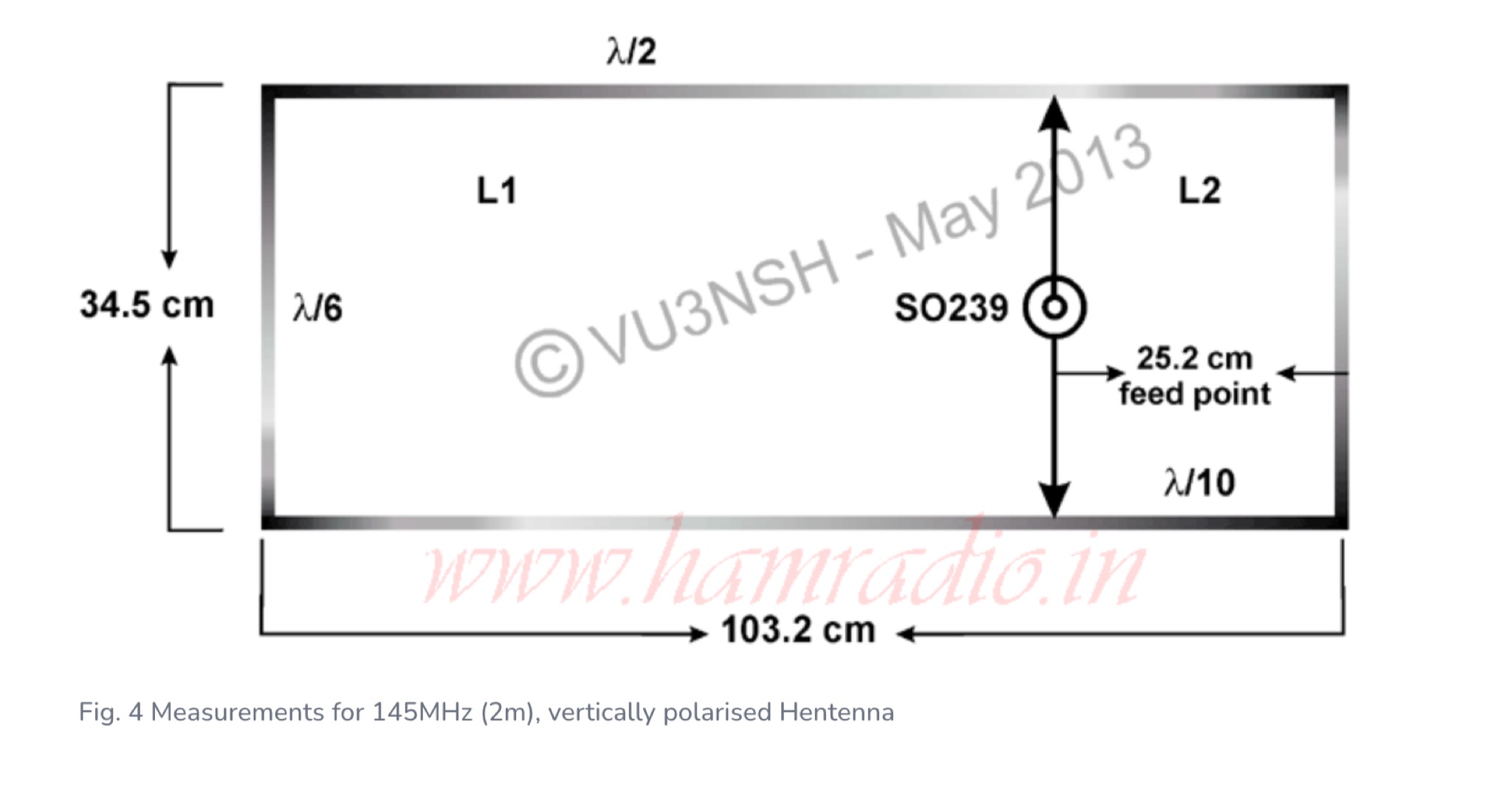 Provides a comprehensive overview of the Hentenna design, construction methods using aluminum tubing, and discusses its bidirectional characteristics with illustrative photos
 -
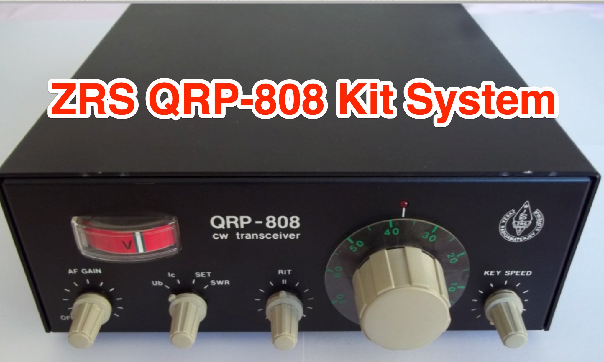 Learn about the ZRS QRP-808 kit system for hams from the 1980s. Discover the improved features of the QRP-808 compared to the QRP-805, including the electrical diagram and assembly instructions. Explore the nostalgic journey of building and tuning this iconic amateur radio station, as shared by experienced ham radio operators. See original photos and insights from enthusiasts like Janko S55WT and Mirko S52PC, offering a glimpse into the history of amateur radio technology. Access PDFs for detailed views and immerse yourself in the world of DIY radio equipment construction and tuning.
 -
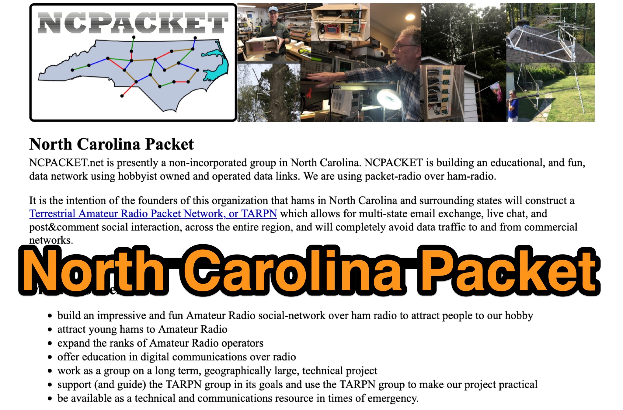 Learn about North Carolina Packet Voice nets and NCPACKET YouTube videos. Get your NCPACKET Callsign Badge to wear at ham club meetings and hamfests. Explore Hamfest Photos and NCPacket news. Discover the North Carolina TARPN Nodes mission statement and the benefits of being off the grid. Find out why TARPN is a great option and compare it with Winlink, APRS, ARES, and MARS. Learn how to build the NCPACKET network, including information on repeater sites and other key components.