Search results
Query: w8ji
Links: 88 | Categories: 0
-
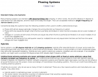 Antennas, Standard Delay Line Systems, Crossfire Phasing or Hybrids
 -
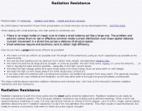 Small antenna, what causes loss and how to increase radiation resistance in small antennas., A description of loss and radiation resistance.
 -
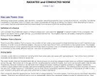 Computers, TV's, and Switching Systems can cause noises to your receiver
 -
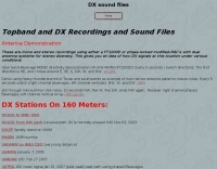 Topband and DX recordings and sound files on 160 meters band
 -
 Technical resource and information on improving ft1000 receiver performance
 -
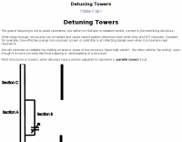 The goal of detuning is not to avoid resonance, but rather to minimize re-radiation and/or current in the interfering structure.
 -
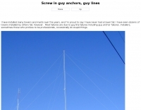
 A 220-ft tower that has five catenary lines, each about 500 feet long. Four of these lines, running NE, SE, SW, and NW support four 1/4-wavelength wire verticals used in a 160-meter four-square antenna.
 -
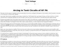 This test circuit is easy to duplicate, and demonstrates the extreme voltages that appear in an amplifier when the load is improper for the amount of drive power applied.
 -
-
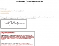 Improper tank adjustment and excessive drive are equally harmful to component life, and either can create splatter
 -
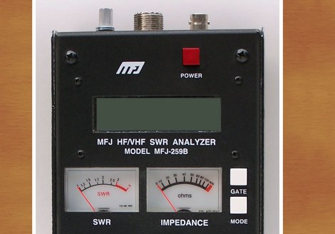 The correct way to calibrate the MFJ-259B analyzer
 -
 Radio Interferences, QRN, or noise, information by W8JI
 -
 Operating a ham station often involves encountering radio frequency interference (RFI), RF feedback, or RF burns, which are frequently misattributed to poor equipment grounding. This resource meticulously dissects these assumptions, asserting that RF grounds on the operating desk often merely mask more significant system flaws. It identifies five primary causes for RF problems, including antenna system design flaws, proximity of the antenna to the operating position, DC power supply ground loops, equipment design defects, and poorly installed connectors or defective cables. The content emphasizes that issues like "hot cabinets" or changes in SWR when connecting a ground indicate substantial RF flowing over wiring or cabinets, a phenomenon known as common-mode current. The article provides detailed explanations of common-mode current generation, particularly from single-wire fed antennas like longwires, random wires, and OCF dipoles, which inherently present high levels of RF in the shack. It also illustrates how vertical antennas, lacking a perfect ground system, can excite feed lines with significant common-mode current. Through simulations, the author demonstrates how a dipole without a proper _balun_ can cause RF problems at the operating desk, showing current patterns and voltage distributions on feed line shields. The discussion extends to the proper application of _RF isolators_ and _ferrite beads_, clarifying their role in modifying common-mode impedance on cable shields and cautioning against their use as a band-aid for fundamental system defects. The resource advocates for correcting the actual source of RF problems, such as antenna system issues or poor connector mounting, rather than relying on internal shack grounding or isolators. It highlights that properly functioning two-conductor feed lines, like coaxial or open-wire lines, should result in minimal RF levels at the operating position, even without a desk RF ground. The author shares personal experience, noting that his stations since the late 1970s have operated without RF grounds at the desks, relying instead on proper antenna system design and feed line integrity.
 -
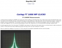 Modification to solve key clicks on FT 1000 MP
 -
 Hams or amateur radio operators and CB operators usually cannot have ideal grounds, but with some care and planning they can have nearly perfect systems
 -
 Common causes of failues, due to wrong clamps. About Guy Anchors
 -
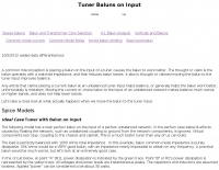 There is a common perception that placing a balun on the input of a tuner causes the balun to work better. The thought is the balun operates with a matched impedance and that reduces balun losses. It also is thought that moving the balun improves balance.
 -
 While intended mainly for antenna loading coils, this article also applies to other resonant systems, such as amplifier tank circuits.
 -
 How to correct keyclick problem in ft1000 and ft1000d radios.
 -
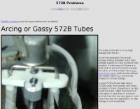 Common problems of the 572B tubes often used in many RF Power Amplifiers
 -
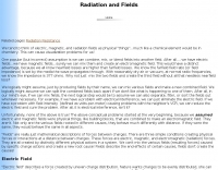 Electric Fields, magnetic fields, electromagnetic fields, losses, fresnel zone, nearfield and farfield
 -
 Single antenna with multiple polarization for diversity, diveristy receivers and propagation effects on signal polarization
 -

-
 About keying speed affecting occupied bandwidth of a transmitter.
 -
 Middle Georgia USA contesting station. Consistent record holder in 160 meter and 40 meter contests.
 -
 The resource, "Conventional Use of Transmission Line," meticulously details the operational principles of transmission lines, emphasizing the Transverse Electromagnetic (TEM) mode of energy transfer. It clarifies that for a line to function purely as a transmission line, all currents must be confined internally, with external fields ideally zero. The discussion differentiates between balanced and unbalanced lines, asserting that while both require equal and opposite currents within the conductors, the key distinction lies in the voltage relationship of each conductor to the surrounding environment. It highlights that a good antenna pattern does not inherently confirm proper feeder balance, and that common-mode currents can lead to RF in the shack and increased noise levels, even without pattern distortion. The article further explains that a transmission line can become a radiating conductor if energy is applied in a non-TEM mode, leading to common-mode issues. It cites classic texts like Jordan and Balmain's "_Electromagnetic Waves and Radiating Systems_" and Kraus's "_Antennas_" to support its definitions of TEM mode operation. The content also explores non-transmission line applications of parallel or concentric conductors, such as _coaxial dipoles_ and _folded dipoles_, which intentionally operate in non-TEM modes for antenna functionality. The author, _W8JI_, stresses that simply measuring equal currents is insufficient to confirm a balanced feeder; phase and voltage balance to ground are equally critical.
 -
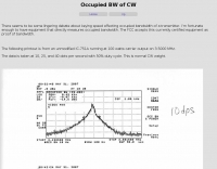
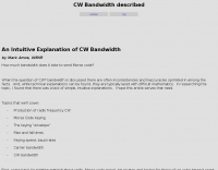 How much bandwidth does it take to send Morse code? by Mark Amos, W8XR
 -
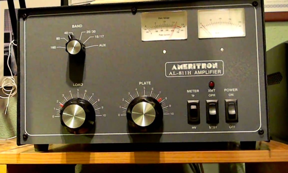 Easiest possible tuning steps using a closed CW key, FM or AM tuning the Ameritron AL-811H
 -
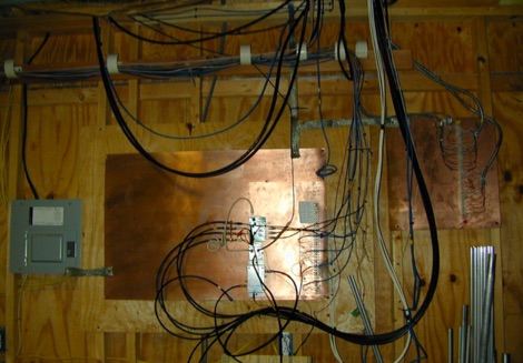 Solution for stations located at secondo floor or higher. Lead lengths to the grounding system are much too long to provide a low-impedance RF ground.
 -
-
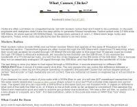 Clicks are most problematic when we try to copy weak signals next to moderately strong signals. How to recognize them, and how to identify clicks problems
 -
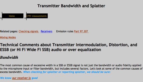 Technical Comments about Transmitter Intermodulation, Distortion, and ESSB (or Hi Fi Wide Fi SSB) audio or over equalization by W8JI
 -
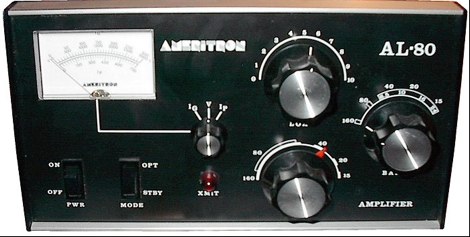 An article on popular AL80 HF power amplifier manufactured by Ameritron since 1980
 -
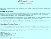 Many antennas and antenna designers neglect the true cause of loss. The major problem using short antennas is the reactance, not the length
 -
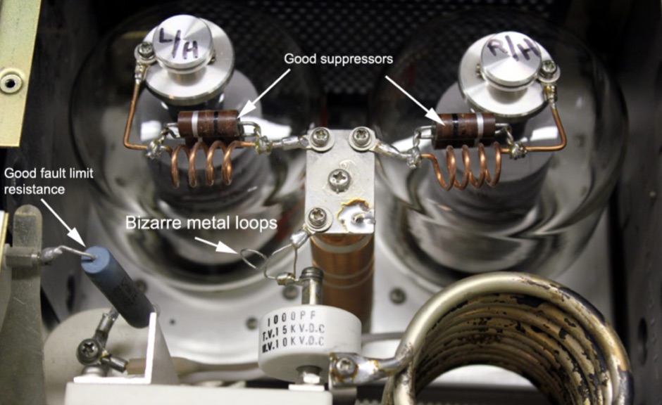 This amplifier had the full treatment, including nichrome hairpins, but they had to be removed because of parasitics or instability.
 -
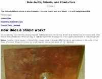 Article about shields, Litz wire, braid, and skin depth. It is still being expanded.
 -
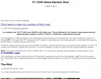
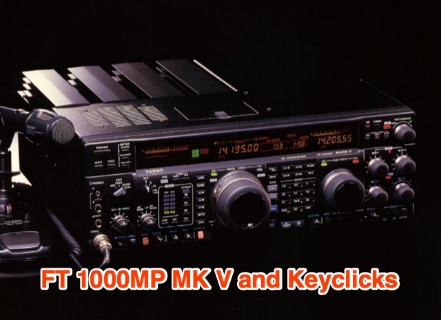 YaesuFT1000MK V stands out with improved close-spaced SSB transmit performance, reversing a trend seen in other modern radios. Featuring a class-A mode, it offers clean HV finals when kept out of ALC. However, two significant flaws persist: the noise blanker causes receiver IM distortion, and the transmitter lacks wave-shaping on CW, resulting in pronounced keyclicks. Preliminary tests reveal strong keyclicks +1kHz and -1kHz, prompting a combined modification to address both issues.
 -
 This resource details **cooling modifications** for Ameritron AL82, AL1200, and AL1500 HF amplifiers, specifically addressing heat issues encountered during high-duty-cycle digital mode operation. The author, WD4NGB, observed excessive heat in the tank area and band switch on an AL82, attributing it to insufficient exhaust over the 3-500 tubes and a complete lack of exhaust over the tank area. The modifications aim to prevent common failures such as damaged band switches and deformed insulating materials by increasing airflow and exhaust area. The page describes adding five holes to the chassis for enhanced cooling to the band switch and tank area, alongside enlarging the exhaust area over the inner 3-500 tube and the tank area on the amplifier cover, utilizing expanded metal for safety and RF shielding. The original cover featured 26.25 square inches of exhaust; the modified version significantly increases this to 48.5 square inches over the tubes and introduces an additional 15 square inches over the band switch. These changes are intended to resolve heating problems encountered during heavy, 100% duty cycle use in modes like RTTY or long SSB contests, which typically generate substantial heat. The article also discusses upgrading to a higher output fan, such as the G2E085-AA05-21, and modifying tube sockets for improved airflow and reduced back pressure, citing Tom Rauch (W8JI) of CTR Engineering as a source for parts.