Search results
Query: 60 meter
Links: 252 | Categories: 3
-
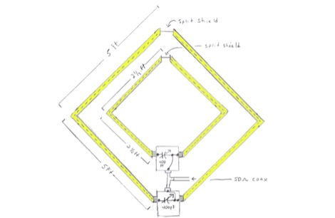
 A monster magnetic loop antenna for 160 meters band. This Magnetic loop is optimized for 1840 Khz + 50 Khz. PDF Article published on La Radiospecola 10.22
 -
 Lights on why 160 meters is so unpredictable and what is being done to reveal its secrets
 -
 A 2 element small footprint 40 meter phased, reversible, downsized quad array antenna.
 -
 A Wire resonant loop antenna for 160 meters band article by N4KC
 -
-
 Delta 160-meter receiving antenna used at FO0AAA
 -
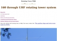 This is the 195-foot tall rotating Rohn 55G tower at W8JI with yagis for 40 20 15 and 6 meter bands.
 -
 This article loaded with nice pictures and schematics, describes a 160-10 meter linear amplifier that uses a pair of 3-500Z triode power tubes. It was designed and constructed by William Moneysmith, W4NFR. The amplifier features fast warm up and 1500-Watt RF output with 100-Watts of drive.
 -
 This PDF document details the construction of a **70 MHz** Big Wheel antenna, a horizontally polarized omnidirectional array. The design utilizes three full-wave loops, each approximately **2160 mm** in diameter, arranged in a triangular configuration. The resource provides mechanical dimensions for the antenna elements and a comprehensive bill of materials, specifying component quantities and types, such as M8 stainless steel bolts, 15x15x1.5 mm square aluminum tubing for spacers, and 8 mm aluminum rod for the arcs. The central hub is constructed from two 160x160x8 mm aluminum plates, with four 40 mm long polyamide insulators supporting the radiating elements. The feed system incorporates a 50 mm diameter aluminum pipe for mounting and a matching stub constructed from a 120x20x2 mm aluminum sheet, connected via M8x10 mm bolts. The resource includes a diagram illustrating the mechanical dimensions and assembly points, including the N-connector fixing point and the center conductor attachment. The project was published on May 25, 2011, by Peter OE5MPL and Rudi OE5VRL. DXZone Focus: PDF | 70 MHz Big Wheel | Mechanical Dimensions | **2160 mm** loop diameter
 -
 Article describing how to homebrew a yagi antenna for 50 MHz, includes plans for a four and five elements yagi beam and details how how match impedence with a gamma match
 -
 The KP3AV Systems website offers a detailed listing of amateur radio repeaters across Puerto Rico, including operational frequencies and tones for VHF and UHF bands. It features sections dedicated to digital modes like DMR and C4FM, as well as information on FRS, GMRS, and MURS. The resource also includes articles on emergency communications protocols and provides access to Spanish-language manuals for various radio equipment. Recent content covers the new open-source FT2 mode for WSJT-X Improved, upcoming 60-meter band frequency allocations and power restrictions effective February 13, 2026, and discussions on 2-meter contacts with Desecheo Island from Puerto Rico. The site also presents U.S. amateur radio band plans and highlights local contesters like Manuel WP4TZ, offering practical insights into portable operations and contest participation.
 -
 EF0603S is a 3 element portable yagi antenna for six meters band by YU7EF
 -
 The X80 multi-band HF vertical antenna, a commercial iteration of the Rybakov design, exhibits a physical length of 5.5 meters, or approximately 18 feet, and is constructed from aluminum tubing. It operates as a non-resonant vertical, requiring an external antenna tuner for impedance matching across its intended operating frequencies. The antenna's design incorporates a 1:4 UNUN at its base, facilitating a nominal 50-ohm feed point impedance for the coaxial cable. Performance observations indicate effective operation on 40 meters, 20 meters, 15 meters, and 10 meters, with reduced efficiency on 80 meters and 160 meters due to its relatively short electrical length for these lower bands. Comparative analysis with a G5RV dipole and a half-wave end-fed antenna reveals the X80 offers a lower take-off angle, beneficial for DX contacts, particularly on the higher HF bands. Field tests conducted with an Icom IC-706MKIIG transceiver and an LDG AT-100ProII autotuner demonstrate the X80's ability to achieve acceptable SWR across 80m through 10m. The antenna's compact footprint and ease of deployment make it suitable for restricted spaces or portable operations, though its performance on 80 meters is noted as a compromise compared to full-size resonant antennas.
 -
 Demonstrates various practical amateur radio projects and technical discussions through video episodes. One episode details cutting and retuning a _1/4 wave shorted stub_ from 101.7 MHz to 107.5 MHz to safeguard a transmitter's driver stage, alongside insights into advanced _160-meter antenna systems_ like eight-circle arrays and beverage antennas. Another segment covers upgrading firmware on an _ATS-20+_ receiver using AverDudes for improved display and functionality, and a detailed guide on using D-Star DR mode on an _ICOM ID-52A_ for international repeater programming. Additional content includes a deep dive into _OpenHamClock_ as a potential replacement for the HamClock project, updates on _Raspberry Pi 5_ running Trixie OS, and a review of the Choyong LC90 Internet radio with AI integration. The series also features "Ham College" episodes, which meticulously prepare viewers for the Technician Exam by covering topics such as antenna and transmission line measurements, SWR interpretation, and the functions of basic electronic components like rectifiers, relays, and transistors. Practical advice on coaxial cable characteristics, dummy loads, and proper soldering techniques is also provided.
 -
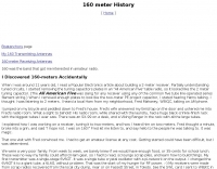 Includes W1BB Stew Perry letters, and a sample QSL cards of dated 1963
 -
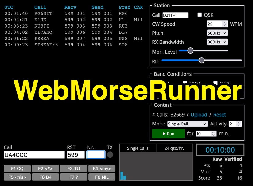 Web Morse Runne is an online CW (Morse code) contest simulator developed by DJ1TF - Thomas Fritzsche. This tool allows users to practice their Morse code receiving and sending skills in a simulated contest environment. Key configurable parameters include CW speed, with options ranging from 300Hz to 900Hz, and RX bandwidth, adjustable from 100Hz to 600Hz. Users can also set a monitor level and simulate various band conditions. The interface includes counters for calls and QSOs per hour, along with a timer. Pre-defined function keys are available for common contest exchanges such as F1 (CQ), F3 (TU), F6 (B4), F7 (?), and F8 (NIL). The simulator is designed for ham radio operators looking to improve their CW contesting proficiency.
 -
 A presentation of a HF multi-band sloper antenna. This antenna project is for low band operations, and antenna presented in this article works on 40 80 and 160 meters band. Article is in Polish.
 -

-
-
 Modeling small 160 meter antennas, with a focus on the vertical H antenna
 -
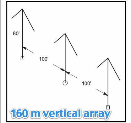 Article by N6LF on a top band vertical antenna array system
 -
 Presents SWR analysis of an **Alpha-Delta DX-LB Plus** multiband wire antenna, installed as an inverted-V at 40 feet with ends at 15 feet, using an RigExpert AA-54 analyzer. The resource provides a full SWR sweep from 0.1 MHz to 54 MHz, followed by detailed SWR graphs for individual amateur bands including 160m, 80m, 40m, 30m, 20m, 17m, 15m, 12m, 10m, and 6m. The analysis highlights the narrow bandwidth on 80m and 160m due to loading coils, necessitating tuning for specific operating frequencies. It notes excellent SWR performance across the entire 40m band and good results on 10m, also requiring tuning. The author shares personal experience with the antenna, including a 17,000 km QSO on 20 meters, and discusses plans to replace it with a homebrewed parallel **fan-dipole**.
 -
 The 160 meter ground plane is constructed from #10 stranded insulated wire available in most hardware stores. The feedpoints / tiepoints use PVC pipe T-sections Article by W1TR
 -
 Hi-Z Antennas offers specialized high-impedance receiving systems, primarily focusing on phased vertical arrays for HF reception. Their product line includes preamplifiers designed for shortened vertical antennas, featuring optimized 15dB gain and array-matched characteristics. These components are engineered to enhance weak signal reception and improve signal-to-noise ratio across the HF spectrum. The company provides controllers for managing multiple vertical elements in a phased array configuration, enabling directional reception patterns. These systems are particularly effective for mitigating local noise and interference, a common challenge in urban and suburban operating environments. Specific offerings include solutions for 160-meter and 80-meter bands, addressing the unique requirements of low-band DXing. Technical details often reference components like the 2N3866 transistor in preamp designs and discuss concepts such as out-of-band attenuation. The focus remains on optimizing receiving antenna performance through impedance matching and active amplification, rather than transmit capabilities.
 -
 Topband and DX recordings and sound files on 160 meters band
 -
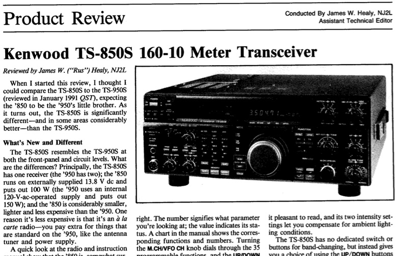 QST Magazine, 1991 July, review of the Kenwood TS-850S 160-10 Meter Transceiver
 -
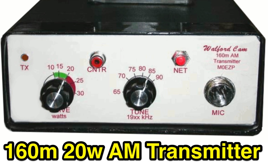 Born as a companion transmitter for the Yaesu FRG-7 receiver has become a stand alone tramsmitter for 160 meters band
 -
 The Lake Monroe Amateur Radio Society serves Seminole County and Central Florida, operating two 2 meter repeaters on 147.285 +600 and on 146.805 -600
 -
 Modeling compact 160 meter antennas, inverted L, half wave dipoles and linearly loaded dipole
 -
 The NB6Zep Antenna, an electrically shortened 80-meter end-fed wire, addresses space constraints for low-band operation by integrating two loading coils into a 37-foot wire. This design, modeled with _EZNEC_, explores configurations like the quarter-wave sloper and inverted-L, with the latter providing a more vertical radiation pattern and practical backyard deployment. The resource details specific coil construction, recommending 21 uH coils made from _BW coil stock #3026_ or similar, and outlines wire segment lengths for optimal tuning. Performance analysis indicates a radiating efficiency of approximately 27% with good ground conductivity, resulting in a signal typically 3-4 dB down compared to a full-size quarter-wave vertical. The antenna exhibits a narrow bandwidth, around 50 kHz, due to its high Q, necessitating a tuner for broader band operation. Feedpoint impedance is low, with ground resistance playing a critical role in achieving a usable SWR. The article emphasizes the importance of an effective ground rod at the feedpoint for proper operation and tuning, suggesting an antenna analyzer for precise adjustments. It confirms the antenna's suitability for DX, citing successful contacts from Oregon to the East Coast and Hawaii on a 160-meter variant, making it a viable option for urban operators seeking low-angle radiation on 80 meters.
 -
 22 Different Wire Antennas for the 160 Meter Band, Random Length Radiator Wire, delta loop, loop antennas, off-centered antennas, sloper, dipoles, Z antenna, Zepp and Clothesline Antennas
 -
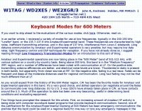 Evaluation of various operating modes on 600 meters
 -
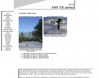
 A 220-ft tower that has five catenary lines, each about 500 feet long. Four of these lines, running NE, SE, SW, and NW support four 1/4-wavelength wire verticals used in a 160-meter four-square antenna.
 -
 An interesting article about planning and testing beverage antennas for 80 and 160 meters in a rural location
 -
 Demonstrating the construction of a short dipole antenna tailored for the 60 meter band, this resource provides detailed instructions for radio enthusiasts with limited space. The design incorporates inductive loading using two inductors (L1/L2) made from PVC tubes, allowing for effective operation on 5 MHz. The antenna consists of 12 meters of wire, divided into four sections, with specific dimensions and materials outlined for optimal performance. Results from users indicate that this antenna can significantly enhance DXing capabilities on the 60 meter band. Feedback from operators suggests that while the design is effective, adjustments may be necessary based on individual setups, such as coil diameter and wire gauge. Many users report successful construction and operation, with some experimenting with variations to improve resonance. The practical application of this antenna design has led to successful contacts and improved signal quality, making it a popular choice among 60 meter band operators.
 -
-
 Article from 73 Amateur Radio Today about experimenting on ferrite loops transmitting loop antennas for 80 and 160 meters bands.
 -
 An amplifier made using an old HT-41 Hallicrafters Amplifier and adding the 160 meters band By W4NFR
 -
 A 160W linear amplifier for 4 meters band based on GI0GDP
 -
 W/VE amateurs work as many amateur stations in as many DXCC countries of the world as possible on 160, 80, 40, 20, 15, and 10 meter bands. Foreign amateurs (also including KH6, KL7, CY9, and CYØ) work as many W/VE stations in as many of the 48 contiguous states and provinces as possible.
 -
 Accessing this interface provides entry to one of the largest databases for amateur radio voice repeaters, encompassing over 8000 entries from more than 60 countries. The resource supports both desktop and mobile access, with a default display based on browser type, or forced via a "force" parameter (e.g., relais.dl3el.de?force=mobile). Users input a QTH-locator to find local repeater information. The database integrates FM-Funknetz servers and hotspots, potentially creating duplicate entries but ensuring new FM-Funknetz repeaters are immediately displayed. DMR repeater information, including status and talkgroup configurations, is sourced directly from DMR+ / ircDDB and Brandmeister systems, with real-time updates for active and default talkgroups. C4FM/Wires-X installations, particularly MMDVM-based gateways not listed in Yaesu's database, are identified through Brandmeister dashboard descriptions, marked with "W-x" or "W-x#MMDVM" for manual entries. D-Star repeater data from ircddb or QuadNet2 is also incorporated, with entries marked (i), (o), or (d) for manual additions. An APRS interface allows searching by callsign, using Sassan, DL3NCK's database, and offers a mobile-friendly, auto-refreshing display that follows an APRS station. Output data can be generated in GPX format for offline smartphone maps or CSV for spreadsheet applications. The database also attempts to determine valid repeater offsets based on IARU region and frequency, indicated by a "." after the frequency.
 -
 The page provides detailed instructions on how to build a 60 meter End Fed Half Wave Antenna Tuner, with large pictures and diagrams. It is aimed at amateur radio operators looking to construct their own antennas for the 60 meter band.
 -
 A very active repeater system in NYC streaming live 24/7 on thier website & on shoutcast under the listing WB2HWW & also can be heard world wide on 10 meters 29.660 with links on Echolink & IRLP
 -
 The resource provides coaxial cable attenuation data, listing signal loss in dB per 100 feet for various cable types across a frequency range from 1 MHz to 5.8 GHz. The initial table details attenuation for cables such as _RG-58_, _RG-8X_, and RG-213, with impedance values of 50 ohm or 75 ohm, at frequencies up to 1 GHz. For example, _RG-58_ exhibits **0.4 dB** loss at 1 MHz and **21.5 dB** loss at 1 GHz per 100 feet. A subsequent table expands on this data, including LMR series cables like _LMR-400_ and LMR-600, along with other types such as 9913F7 and RG214. This section covers frequencies from 30 MHz to 1,500 MHz, also noting the outer diameter of each cable. For instance, _LMR-400_ (0.405" diameter) shows **0.7 dB** loss at 30 MHz and 5.1 dB loss at 1,500 MHz per 100 feet. The final section focuses on VHF/UHF/Microwave amateur and ISM bands, presenting attenuation in dB per 100 feet (and meters) for frequencies including 144 MHz, 450 MHz, and 2.4 GHz. This table includes larger diameter hardline options like 1/2" LDF and 7/8" LDF, in addition to flexible coaxial cables. For example, 1/2" LDF cable demonstrates **0.85 dB** loss at 144 MHz and 6.6 dB loss at 2.4 GHz per 100 feet. DXZone Focus: Coaxial cable attenuation | LMR-400 | RG-58 | 5.8 GHz
 -
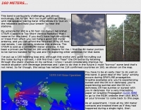
 The 160-meter amateur radio band, spanning 1.8 to 2 MHz, was historically the lowest frequency amateur allocation until the introduction of the 630-meter and 2200-meter bands. ITU Region 1 allocates 1.81–2 MHz, while other regions use 1.8–2 MHz. This band, often called "Top Band" or "Gentleman's Band," was established by the International Radiotelegraph Conference in Washington, D.C., on October 4, 1927, with an initial allocation of 1.715–2 MHz. Effective operation on 160 meters presents significant challenges due to the large antenna sizes required; a quarter-wavelength monopole is over 130 feet, and horizontal dipoles need similar heights. Propagation is typically local during the day, but long-distance contacts are common at night, especially around sunrise and sunset, and during solar minimums. The band experienced a resurgence after the LORAN-A system was phased out in North America in December 1980, leading to the removal of power restrictions.
 -
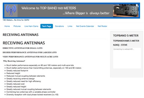 A review of all possible receiving antennas for top band 160 meters
 -
 The article, "Using 75 Ohm CATV Coaxial Cable," details methods for employing readily available 75-ohm CATV hardline in standard 50-ohm amateur radio setups. It addresses the inherent impedance mismatch and practical considerations, such as connector compatibility, for hams seeking cost-effective, low-loss feedline solutions. The resource specifically contrasts common 50-ohm cables like RG-8, RG213, and _LMR-400_ with 75-ohm hardline, highlighting the latter's lower loss characteristics, particularly at VHF and UHF frequencies. It explores two primary approaches to manage the impedance difference: direct connection with an acceptable SWR compromise and precise impedance transformation. The direct connection method acknowledges that a perfect 1:1 SWR is not always critical, especially when using low-loss coax. For impedance transformation, the article explains the use of half-wavelength sections of coax to reflect the antenna's 50-ohm impedance back to the transmitter, noting its single-frequency effectiveness. It also briefly mentions transformer designs using toroid cores and a technique involving two 1/12 wavelength sections of feedline for broader bandwidth. The content further clarifies the concept of _velocity factor_ for calculating electrical versus physical cable lengths, providing a generic formula for precise length determination. It notes that while half-wave matching is practical for 10 meters and above, it can result in excessively long runs for lower bands like 160 meters, potentially adding **250 feet** of cable. The article also mentions achieving a usable bandwidth of 28.000 MHz up to at least **28.8 MHz** on 10 meters with specific transformation techniques.
 -
 160-10 Meters 1500 Watt Amp - W4NFR
 -
-
 A project for a vertical antenna for 60 to 20 meters by KV5R