Search results
Query: LC meter
Links: 125 | Categories: 1
Categories
-
 This article describes the phases for the construction of a Yagi antenna. The calculations of the parameters are made using 4NEC2 software. This type of antenna is used for transmissions and receptions of electromagnetic waves. The project shown here refers to the frequency of 433.92 MHz.
 -
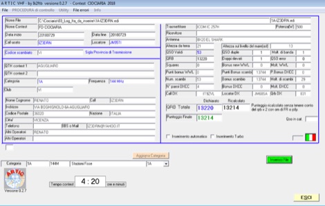 ARTIC is a specialized software tool designed for amateur radio operators participating in VHF contests, offering log checking functionalities. It specifically caters to Italian and Swiss VHF contests, such as the IAC (Italy) and SWAC (Switzerland), ensuring adherence to contest rules and accurate score calculation. The software is developed by IK2FTB and provides a dedicated platform for post-contest log analysis. This resource includes download links for various versions of the ARTIC software, with updates noted for different contest years and rule sets. For instance, versions like ARTIC 2022 and ARTIC 2023 are available, reflecting ongoing development and adaptation to evolving contest parameters. The page also features links to related contest resources and information, providing a centralized hub for VHF contesters to manage their logs and verify their entries.
 -
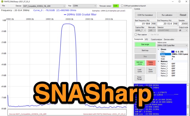 SNASharp is a free software application designed to work with scalar network analyzers compatible with NWT software from DL4JAL. It is used to measure and analyze the scattering parameters (S-parameters) of microwave devices. Provide several measurements and analysis tools including Smith chart, Polar plot, S-parameter tables, Transmission line calculator
 -
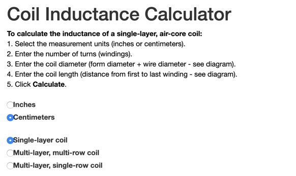 This online calculator will return the inductance of a coil. It will ask you the total number of turns, the total diameter of the coil and its lenght, from the first winding to the last. Obtaining the correct inductance in winding a coil can be easy if you already know how many turns are needed. Available in inched and centimeters,
 -
 An **Arduino LC Meter** provides an accessible solution for precisely measuring inductance and capacitance values, crucial for RF circuit design, filter tuning, and troubleshooting in amateur radio applications. This project details the construction of a low-cost, accurate instrument using readily available components, making it an attractive alternative to commercial units for hams and electronics enthusiasts. The build process involves assembling a resonant circuit, integrating an Arduino microcontroller for frequency measurement, and displaying results on an LCD. Key components include an Arduino Uno, a 16x2 LCD, a 74HC14 Schmitt trigger inverter, and a few passive components. The design leverages the Arduino's processing power to calculate L and C values from resonant frequency shifts. Calibration procedures are outlined to ensure measurement accuracy, which is vital for critical RF work. The project includes schematics, a parts list, and the necessary Arduino code, enabling hams to construct a functional LC meter for their workbench.
 -
 The Dipole Bazooka Antenna for 40 meters is a popular choice among amateur radio operators. Its design allows for easy construction using materials like RG58 coaxial cable and PVC. Measurements are calculated using specific formulas; for instance, at a frequency of 7,100 MHz, the total length is approximately 19.74 meters. This antenna offers a performance range of 97% to 99%, with an impedance of 49 to 52 ohms. Additionally, it can handle up to 1 kW of power and requires no modifications for connection.
 -
 EA4EOZ details the construction and testing of 50 MHz traps, a critical component for multiband antenna designs. The project addresses the challenge of sourcing high-voltage capacitors suitable for trap applications, exploring alternatives to expensive doorknob capacitors. The author successfully fabricated a capacitor using 1.6mm double-sided FR-4 PCB material, achieving a capacitance density of **2.6 pF/cm2**. Utilizing the _VE6YP calculator_, specific L and C values of 30 pF and 0.31 uH were determined for a 2cm diameter coil. Both the FR-4 PCB trap and a coaxial cable trap, constructed from _RG-58_, were built and tuned to approximately 50 MHz using a spectrum analyzer. The coaxial cable trap demonstrated superior performance, exhibiting a notch nearly **20dB deeper** than the FR-4 version. This practical comparison provides insights into trap construction for experimental antennas, with the coaxial cable trap selected for an antenna project intended for operation at up to 100 watts.
 -
 Delta loop antennas, particularly the 30 meter variant, offer unique advantages in terms of vertical polarization and omni-directional coverage. The construction process detailed by VE3VN highlights common mechanical and electrical challenges faced by amateur radio operators. Key design considerations include minimizing interaction with existing contest band antennas, achieving low elevation angles for DX chasing, and ensuring the antenna remains off the ground for agricultural clearance. The article provides specific measurements, such as the loop's height and feed point impedance, which are critical for optimizing performance. The use of NEC modeling software illustrates the importance of accurate resonance calculations, revealing how proximity to the tower affects both pattern and impedance. This practical account serves as a resource for hams looking to build effective antennas while navigating typical construction hurdles.
 -
 Chavdar Levkov, LZ1AQ, presents an experimental comparison of small wideband magnetic loops, building on his previous work on wideband active small magnetic loop antennas. His research focuses on increasing loop sensitivity by maximizing the short-circuit current, which is directly tied to the "loop factor" M = A/L, where A is the equivalent loop area and L is its inductance. Levkov's methodology involves reducing inductance and increasing area through parallel or coplanar crossed (CC) configurations, comparing these designs against a reference single quad loop of 1 m2 area. Experimental verification included testing three distinct loop types: a simple quad loop, two coplanar crossed (CC) loops, and eight parallel loops, all designed to have a total geometric area of 1 m2. Measurements were conducted at 1.8, 3.5, 7, and 10 MHz using a small transmitter 270 meters away, with a Perseus direct sampling receiver for precise signal level assessment. The results consistently showed that CC loops, particularly Loop 5 (two CC circular loops with 1.44 m2 total area), yielded significantly higher currents, up to 9.1 dB over the reference loop at 3.5 MHz, validating M as a reliable predictor of loop sensitivity. Numerical simulations using MMANA further corroborated the experimental findings, demonstrating an almost perfect correlation between the calculated M factor and the induced loop current for 15 different loop models. Levkov concludes that CC loops offer superior sensitivity for a given loop area, while parallel loops are advantageous for minimizing physical volume. Practical recommendations suggest using loops with an M factor greater than 0.5 uA/pT for quiet rural environments, and he provides a spreadsheet tool, WLoop_calc.xls, to aid in optimizing loop configurations for specific operational needs.
 -
 Addresses the common challenge of constructing effective dual-band antennas for VHF/UHF operations, specifically detailing a J-pole design. It covers the theoretical underpinnings, including calculations for quarter-wavelength radiator and stub sections, accounting for velocity factor and design frequency. The resource provides practical construction guidance using readily available materials like TV twin lead and coaxial cable, culminating in an antenna with a total length of approximately 52 inches. Performance metrics are presented, showing a measured SWR of 1.7:1 or better across most of the 2-meter band and less than 2:1 across the 70-cm band. These SWR measurements, referenced to 50-ohm impedance, were taken at the transmitter end of the feed line. The article also touches upon the necessity of a balun for proper impedance matching between the balanced J-pole and unbalanced coaxial feed line, suggesting a split-core cylindrical ferrite for this purpose.
 -
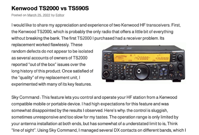 The Kenwood TS-2000, often dubbed a "Swiss Knife" transceiver, integrates HF, VHF, and UHF capabilities, but its operational compromises, such as a noisy cooling system and a cluttered user interface, led to user dissatisfaction. The author noted the TS-2000's cooling fans frequently operated at two loud speeds, making extended listening unpleasant, and observed a cluttered internal layout hindering airflow. Conversely, the Kenwood TS-590S, a dedicated HF transceiver covering 160m through 6m, offers a significantly quieter operation due to two variable-speed cooling fans and a more spacious internal component layout. Its front LCD display features larger characters and improved backlighting, enhancing readability. The TS-590S also boasts an 18-band audio equalizer, eliminating the need for external audio processing equipment like the _W2IHY EQplus_, and a built-in USB port for seamless CAT control and digital mode operation, a notable upgrade from the TS-2000's legacy serial ports. Performance-wise, the TS-590S demonstrated a perceived **+6 dB** signal increase on the S-meter compared to the TS-2000, and superior reception of weak, near-noise-level signals. Its comprehensive filtering, including effective bandpass and notch filters, along with improved noise blanker (NB) and noise reduction (NR) capabilities, allows for better signal isolation and interference mitigation, even outperforming an external _MFJ-1025_ noise suppressor in some reported cases.
 -
 The DIY Power Meter project utilizes the _INA226_ high-side power monitoring chip, paired with an ATtiny85 microcontroller, to measure voltage, current, and power, displaying the results on a 128x32 OLED screen. The INA226 communicates via an I2C interface and is programmed with a calibration factor based on the shunt resistance and current register LSB. The project is designed to handle a maximum current of 500mA using a 0.16ohm shunt resistor, which can be adjusted to a 0.2ohm resistor, reducing the full-scale current range to 409mA with a resolution of **12.5uA**. The shunt resistor dissipates only 33mW at maximum current, making 1/4 watt resistors suitable for the setup. The PowerMeter.ino sketch configures the shunt resistance and maximum design current, automatically calculating the calibration factor. The project can be prototyped on a breadboard using an Arduino Uno, employing the Wire library for INA226 and OLED communication, and the u8g2lib library for the OLED display. For the ATtiny85 version, the Adafruit-TinyWireM and Tiny4kOLED libraries are used. The power meter is independently powered by a 3V CR2032 cell, with power switching options including manual switches or DC switched jacks. The low-side n-channel MOSFET switch configuration is tested but introduces voltage drop issues, making manual switching a more reliable option until a suitable DC switched jack is found. DXZone Technical Profile: INA226 | ATtiny85 | OLED Display | Power Meter
 -
 This program simplifies the complex jumper calculations for the PRF1520 radio, which can be a pain to determine manually. It supports common crystal frequencies and channel spacings, advising if a desired frequency is achievable. A recent feature allows determining unknown frequencies of a newly obtained radio by setting the jumper positions and other parameters.
 -
 Operating amateur radio repeaters involves understanding frequency offsets, CTCSS tones, and the basic signal flow through a repeater system. This resource details the fundamental concepts of repeater operation, including the distinction between input and output frequencies, the role of **CTCSS (Continuous Tone-Coded Squelch System)** for access, and the typical frequency bands utilized for local communication. It clarifies terms such as "simplex" versus "duplex" operation and provides a diagram illustrating the signal path from a handheld transceiver to a repeater and back to another station, emphasizing the range extension repeaters offer. The article further explains practical aspects like identifying a repeater's offset (e.g., +600 kHz for 2-meter band) and the necessity of programming the correct tone. It compares the operational benefits of using repeaters for local communication over direct simplex contacts, highlighting how repeaters overcome line-of-sight limitations. The content is structured to assist new licensees in confidently making their first repeater contacts, providing a foundational understanding of how these critical infrastructure components facilitate wider area coverage for VHF/UHF amateur radio.
 -
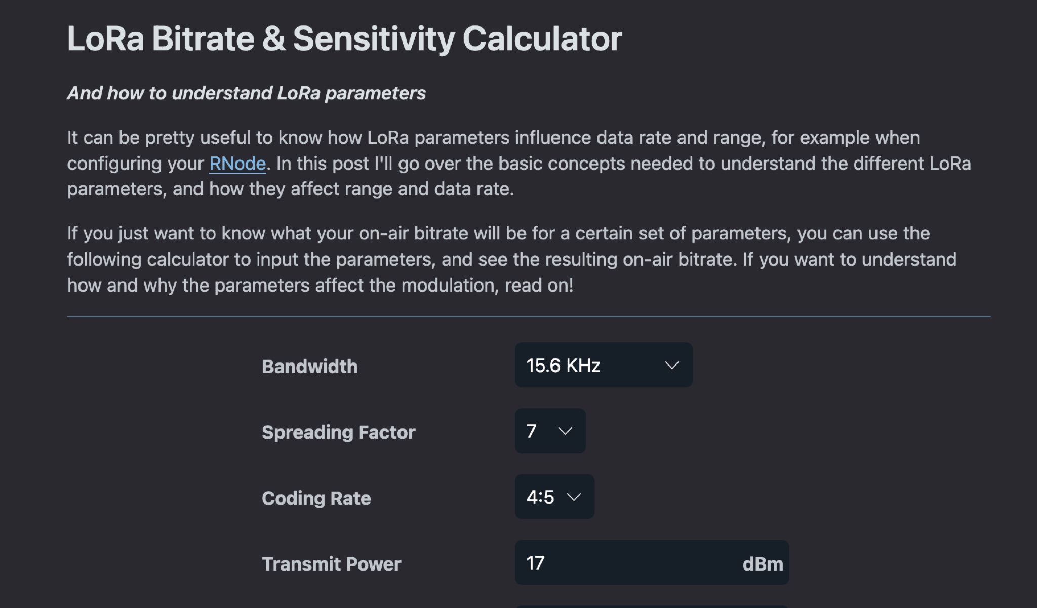 This article explains how LoRa parameters impact data rate and range when setting up a LoRa transceiver. It covers the basic concepts needed to understand different LoRa parameters and their effects on modulation. By adjusting parameters, you can achieve fast data transfers or extend transmission range. The post also offers a calculator to determine on-air bitrate based on input parameters. Understanding LoRa parameters is crucial for optimizing performance and achieving desired communication outcomes.
 -
 The _MFJ-915_ RF Isolator, rated for 1.8-30 MHz and 1500W PEP, exemplifies the product range available from The Ham Shop. The inventory includes various antenna support ropes, such as 3/16" _Dacron Polyester Rope_ in lengths from 100 to 1500 feet, alongside a selection of cables for _SignaLink USB_ sound card interfaces. Specific SignaLink cables are offered for radios like the Yaesu FT-847 (SLCAB847), Yaesu HTs (SLCABVXY), and the Elecraft K3 (SLCABHTY). Additionally, the shop provides modular jumper cables and modules, including the SLMOD8RY for Kenwood/Alinco 8-pin round mic jacks and the SLMOD8RI for Icom 8-pin round mic jacks. The product line supports diverse station configurations, encompassing antennas, coax, baluns, dummy loads, duplexers, insulators, microphones, power supplies, SWR meters, and watt meters.
 -
 A full-wave delta loop antenna, approximately 141 feet in total wire length for the 40-meter band, offers a low angle of radiation, which is highly advantageous for DX operations. This design, optimized for both 30m and 40m, leverages a specific circumference calculation of 1005/F, ensuring resonance on both bands through a simple switching mechanism. The antenna's configuration enhances long-distance communication, making it a practical choice for hams with limited space. The resource details the construction process, including the use of a _Ceramic Knife Switch_ for band selection and an _RG-11_ matching section to achieve optimal impedance. It outlines the precise loop lengths required for each band, along with tuning secrets to ensure efficient operation. Requiring a minimum height of 12 feet, this antenna can be supported by a single mast or tree limb, making it suitable for suburban installations where stealth or space constraints are a factor.
 -
 A versatile digital VFO design utilizing the Silicon Labs Si5351a oscillator chip and Nokia 5110/3310 graphics LCD display, operating from 1-160MHz with dual VFO capability. This microcontroller-based system, powered by an ATmega328 processor, features rotary encoder tuning, selectable step sizes, RIT control, and comprehensive band memory functions. Drawing less than 40mA at 3.3V, it significantly improves upon previous DDS designs' power consumption while offering advanced features like S-meter display, VFO lock, and programmable BFO/CIO offsets. The design achieves flexible functionality through simple hardware implementation and efficient software architecture, making it particularly suitable for QRP and portable amateur radio applications.
 -
 This project outlines a simple, cost-effective 40m band HF dipole antenna design, ideal for beginners. Constructed with insulated copper wire and a 1:1 balun, it offers a 50-ohm impedance, suitable for both 40m and 15m bands due to the harmonic relationship. Calculations account for a K factor, ensuring optimal length and performance. Antenna modeling with 4NEC2 confirms practical access to both bands, though real-world results may vary. Lightweight materials and straightforward assembly make it an accessible and versatile amateur radio solution.
 -
 Online Coil Inductance Calculator. To calculate the inductance of a single-layer, air-core coil, just select the measurement units, enter the number of turns, the coil diameter and the coil length.
 -
 The Olivia digital mode, a **Multi-Frequency Shift Keying (MFSK)** radioteletype protocol, is specifically engineered for robust communication under difficult propagation conditions on shortwave radio bands from 3 MHz to 30 MHz. Developed by Pawel Jalocha in 2003, Olivia signals can be decoded even when the noise amplitude exceeds the digital signal by over ten times, making it highly effective for transmitting ASCII characters across noisy channels with significant fading and propagation phasing. Early on-the-air tests by Fred OH/DK4ZC and Les VK2DSG on the Europe-Australia 20-meter path demonstrated intercontinental contacts with as little as one-watt RF power under favorable conditions. Common Olivia modes are designated as X/Y, where X represents the number of tones and Y is the bandwidth in Hertz, with examples including 8/250, 16/500, and 32/1000. The resource clarifies that Olivia, unlike some other digital modes, produces a constant envelope, allowing RF power amplifiers to achieve greater conversion efficiencies and making it less prone to non-linearity. Operators are advised that **Automatic Level Control (ALC)** can be set higher than no meter movement for MFSK modulation, as long as it's not driven past its high limit, contrary to common misinformation about other digital modes. The Olivia community encourages voluntary channelization on suggested calling frequencies, such as 14.0725 MHz for 8/250, to facilitate initial contacts, especially for signals below the noise floor. The Olivia Digital DXers Club provides links to Groups.io, Facebook, and Discord for community engagement and offers details on QSO parties.
 -
 The **Yaesu FRG-100** shortwave receiver, introduced in 1992, operates across a frequency range of 50 kHz to 30 MHz, accommodating AM, LSB, USB, and CW modes, with an optional narrow-band FM capability. Its physical dimensions are 238 x 93 x 243 mm, with a weight of 3 kg, making it suitable for both portable and fixed station deployments. Power options include standard mains voltage or 12VDC, providing operational flexibility for diverse listening environments. The front panel integrates a manual tuning knob, an analogue signal strength meter, and an LCD display that provides critical information such as frequency, operating mode, memory channel, and time. Users can configure various operational parameters, including tuning steps and bandwidth filters, to optimize reception for specific signals. This review highlights the FRG-100's straightforward interface and its utility for shortwave listening enthusiasts. The design emphasizes user-friendly adjustments for settings, which contributes to its appeal among those interested in general coverage reception.
 -
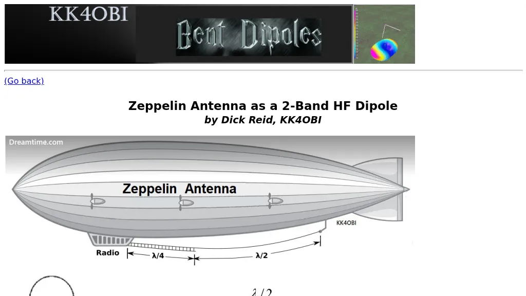 The Zeppelin antenna, a J-type design, is presented as a two-band HF dipole, offering independent operation on harmonically related frequencies. This resource details its electrical configuration, comprising a half-wave radiator end-fed by a quarter-wave matching section, and explores its historical evolution from early Zeppelin airship applications to modern amateur radio use. The article specifically examines how a Zepp antenna tuned to 28.4 MHz (10 meters) exhibits a harmonic relationship with 15.4 MHz (20 meters), noting a frequency ratio of approximately 1.84:1, which deviates from a perfect 2:1 due to factors like elevation, wire separation, velocity factor, and end-effect. Antenna modeling results, including SWR sweeps at 28.4 MHz (1.1 SWR) and 15.4 MHz (1.6 SWR), are provided through Graph 1 and Graph 2, illustrating the antenna's performance across these bands. Current distribution patterns for both the 28.4 MHz (second harmonic) and 15.4 MHz (first harmonic) operations are visually represented in Figure 2 and Figure 3, respectively. The author also includes a 4NEC2 model's "Symbol Conversion file" definitions and calculated #14 wire dimensions for achieving resonance at 28.4 MHz, with the antenna positioned at a height of 33 feet. The discussion further highlights the antenna's versatility, suggesting its potential as a single-band, center-fed, 15.4 MHz half-wave folded end dipole when fed at a specific low current point. This analysis provides practical insights into constructing and optimizing a multi-band Zepp antenna for HF operations, emphasizing its unique harmonic characteristics and physical compactness.
 -
 This article describes a DIY RF field strength meter project inspired by VK3YE's "The Squeakie" design. The device, built around a 555 timer IC and a 1N4148 diode, converts RF signal strength into audible tones with proportional pitch. The author enhanced the original design by adding volume control, LED indication, and digital readout capabilities using an Arduino Nano and LCD display. The completed project functions as a versatile RF detection tool, suitable for antenna testing and fox hunting, while offering multiple output methods: audio, visual, and digital measurement display.
 -
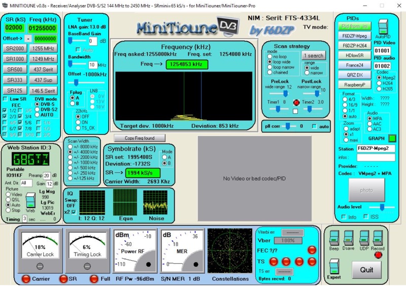 Receiving Digital Amateur Television (DATV) signals requires specialized software to interface with hardware tuners and decode the video stream. The _MiniTioune_ software, developed by F6DZP, serves this purpose, providing a Windows-based application for DVB-S and DVB-S2 reception and analysis. It is designed to work in conjunction with _MiniTiouner_ hardware, enabling hams to monitor DATV transmissions, including those from the QO-100 geostationary satellite. The resource outlines the initial setup process, including connecting the MiniTiouner hardware via a high-quality USB2 mini cable and running diagnostic test software. It details how to configure essential parameters such as symbol rate (SR), FEC rate, and DVB mode for various signal sources, from domestic satellite dishes to local DATV transmitters. Troubleshooting steps for common issues like "no video displayed" are also provided, often pointing to corrupted software filters or incorrect _Auto PID_ settings. Advanced features like the Web monitor for remote signal reporting and integration with _VLC_ media player for more tolerant decoding of non-DVB compliant signals are covered. The document also references a comprehensive user guide by W6HHC for the _MiniTiouner-Express_ system, which utilizes the same software, offering further in-depth assistance for operators.