Search results
Query: aluminum
Links: 125 | Categories: 0
-
 The article describes the construction of a Lindenblad antenna, which is well-suited for receiving signals from low-orbiting weather satellites. The key points are: The Lindenblad antenna has an omnidirectional horizontal radiation pattern and is optimized for low to medium elevation angles, making it ideal for tracking passing satellites near the horizon. It is designed to receive circular polarization, which is common for weather satellite signals. The antenna is constructed using 4 folded dipole elements arranged on a cross-shaped frame. The necessary materials include a plastic junction box, PVC tubing, and aluminum rods to form the dipole elements. The article provides detailed instructions for preparing the components, assembling the dipoles, and connecting the feed lines to create the complete antenna. The completed antenna can be mounted on a vertical support, with the dipole elements angled at 30 degrees from horizontal, to optimize reception of the passing satellites. The author notes that the design was originally published in a now-defunct magazine, Meteo Satellite Inf", in 1993
 -
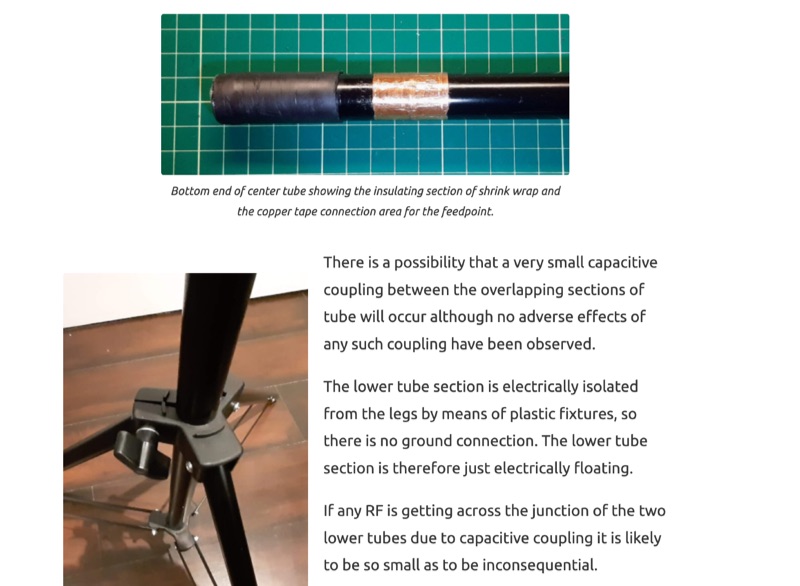 A 13-foot total radiating element length is achieved by combining a Buddipole Long Telescopic Whip with 4 feet of modified tripod tubes, forming a low-profile, multiband antenna for **POTA** operations. The resource details the transformation of an Amazon Basics Aluminum Light Photography Tripod Stand, focusing on electrically isolating the top two radiating sections from the bottom support. John, VA3KOT, outlines component sourcing, including the 9-foot 4-inch fully extended whip, and emphasizes using adhesive copper tape for reliable electrical contact and conductive grease to prevent oxidation at tube connections. The construction process, while not requiring specialized tools, highlights careful assembly to ensure proper electrical conductivity and mechanical stability. The author's experience with this setup suggests its effectiveness for portable activations, offering a discreet profile compared to larger antenna systems. The design prioritizes ease of deployment and transport, making it a practical solution for operators seeking a compact yet versatile antenna for field use.
 -
 Constructing a double bazooka antenna for the UHF band, specifically tuned for 435 MHz, involves a straightforward process detailed with step-by-step imagery. The design leverages readily available _RG213 coaxial cable_, cut to precise lengths derived from formulas: 140.208 / F (MHz) for the radiating element and 99.06 / F (MHz) for the coaxial section. This approach yields a highly effective vertical polarization antenna, suitable for local ragchewing or repeater access. My own field experience with similar coaxial designs confirms their robustness and ease of deployment. The article emphasizes critical steps like short-circuiting cable extremities, interrupting the braid at the center, and securing an insulating support. It also covers preparing the definitive mounting with a quality feedline, noting that RG58 is acceptable for temporary use but better options exist for permanent installations. Weatherproofing is crucial for longevity, achieved through PVC electrician's tube, glue, and heat-shrink tubing. The final assembly is designed for mounting on a small aluminum mast, with the feedline routed internally. The reported SWR measurement is very satisfactory, showing approximately **+/- 3%** HF return, indicating excellent impedance matching at the target frequency.
 -
 A DIY cantenna can extend your WiFi range by building a 2.4 GHz high-gain antenna using accessible materials. The design, based on waveguide principles, uses a cylindrical tube to capture WiFi signals and can even connect to access points half a mile away in ideal conditions. While the ideal tube diameter was hard to find, a 4-inch aluminum dryer vent was chosen despite theoretical limitations. The cantenna offers a cost-effective, functional boost for your wireless network.
 -
 The article describes a high-gain, compact beam antenna design for the 2-meter band (144-146 MHz). The NSH 4x4 Boomer is a 4-element antenna that is mounted on a 4-foot boom with an 8.2 dB gain, 1.2:1 SWR, and a front-to-back ratio of 18 db. It is designed for mobile operations and little area, making it perfect for field usage such as disaster management. The design employs regularly spaced parts with a straightforward gamma match for tuning, and the construction materials include a square boom and polished aluminum tubes. In local and portable tests, the antenna worked regularly, achieving contact distances of up to 15 kilometers.
 -
 The All-Copper J-Pole Antenna Construction for 2 Meters document outlines a specific build methodology for a VHF base station antenna. It addresses common issues like dissimilar metal corrosion and feed line degradation often encountered with aluminum J-Pole designs, proposing an all-copper and brass solution with soldered connections for enhanced durability and electrical performance. This resource provides a comprehensive parts list in Table 1, detailing precise copper tubing lengths and other necessary hardware components. The design emphasizes DC grounding, which eliminates the need for insulating materials and simplifies installation, contributing to a robust and weather-resistant structure. Michael P. Hood, KD8JB, details an assembly process estimated to take approximately one hour, with total material costs projected under $15. The antenna's construction focuses on rigid copper tubing and fittings, ensuring long-term integrity for 144 MHz operation.
 -
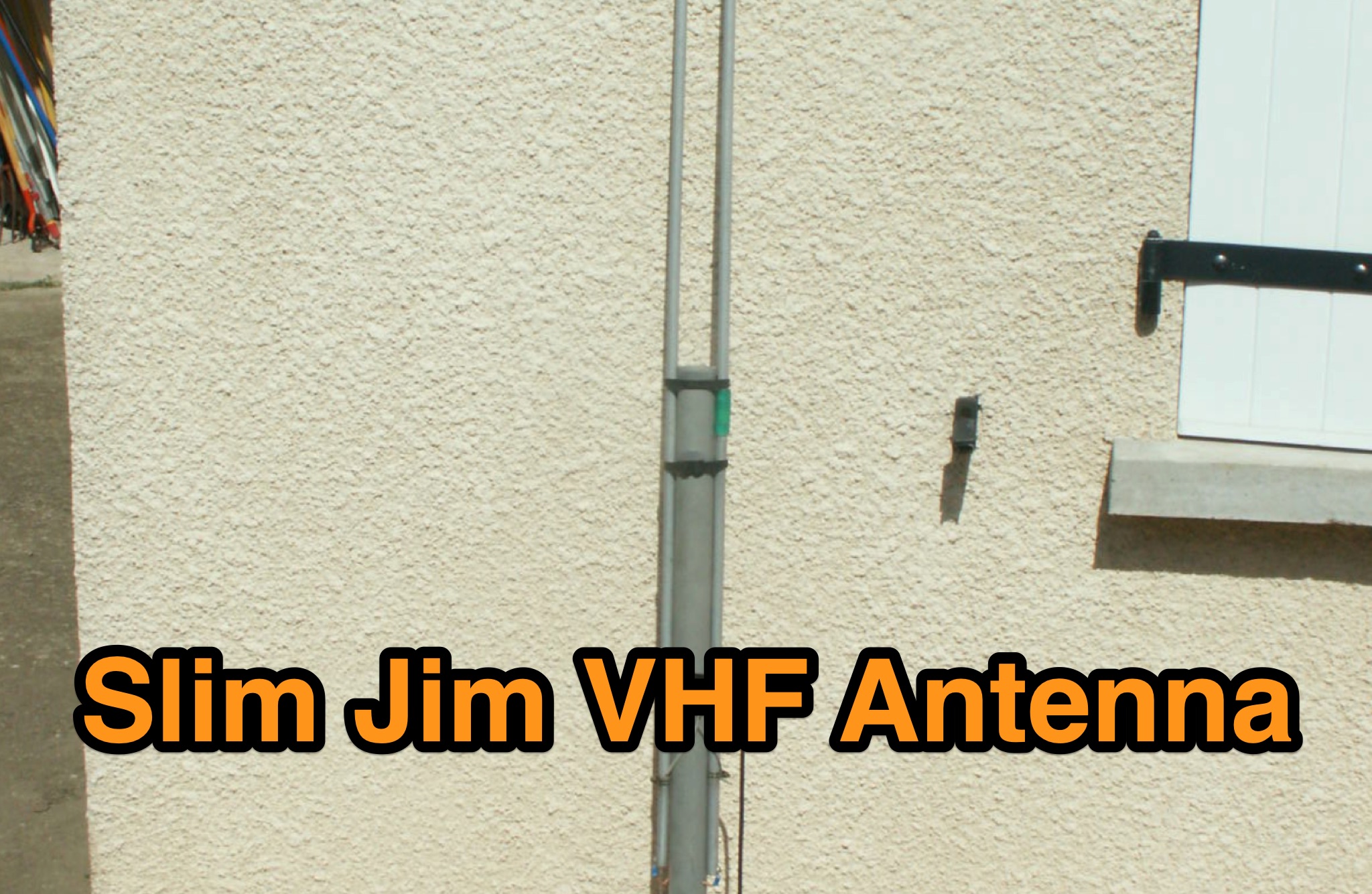 The Slim Jim VHF antenna, originally designed by G2BCX, is a folded half-wave dipole fed by a quarter-wave matching section. This version, built from a recycled professional aluminum dipole, demonstrates that various materials—such as copper, brass, or twin-lead—can be used. The article details the antenna’s construction, required materials, and tuning process, emphasizing mechanical stability and ease of assembly. With proper adjustment of the feed point, it provides excellent SWR across the band. Its durability and simplicity make it a practical and efficient VHF antenna solution.
 -
 Building an efficient antenna begins with selecting the right aluminum stock. This article provides a comprehensive guide to sourcing aluminum materials for antenna construction. It covers different aluminum grades, their tensile strengths, tempering options, and their suitability for various antenna components. The article also recommends reputable suppliers in the UK, making it a valuable resource for antenna builders seeking durable and high-performance materials.
 -
 The resource details the construction of a J-pole vertical antenna specifically engineered for motorcycle mounting, addressing the common issue of interference with top cases. It outlines the fabrication process, beginning with an aluminum angle bracket for secure attachment to the lateral support, followed by the creation of the antenna's base from an 8mm threaded rod bent into a U-shape, approximately **40mm** wide. The article specifies the precise method for coaxial cable connections using eyelets and 3mm screws, ensuring robust contact. Further construction steps involve fitting a 10mm aluminum tube onto the threaded rod, with a screw securing the radiating element and establishing core contact. The design prioritizes mechanical stability against vehicle vibrations over fine-tuning SWR with sliding collars. Initial testing yielded a _SWR_ of **1.2** across a significant portion of the band, with improvements noted by optimizing the coaxial braid contact point near the support bracket. The document provides practical insights into material selection and assembly, emphasizing durability for mobile operation. It concludes with aesthetic options, allowing the builder to paint the antenna or retain its natural aluminum finish, making it a functional and adaptable solution for UHF motorcycle communications.
 -
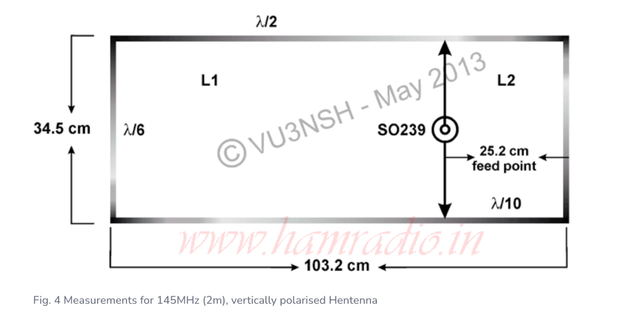 Provides a comprehensive overview of the Hentenna design, construction methods using aluminum tubing, and discusses its bidirectional characteristics with illustrative photos
 -
 Details the construction of a portable 6-meter 4-element quad antenna, specifically designed for VHF and Field Day operations. The design emphasizes portability and rapid field assembly, utilizing a 10-foot boom, #12 bare wire elements, and fiberglass electric fence post spreaders. It presents specific dimensions for reflector, driven element, and directors, including spreader lengths, circumferences, and corner marks, all derived from a G0KSC design and modeled in EZNEC. The resource outlines the fabrication of synthetic lumber hubs that allow post-assembly adjustments along the boom, and describes spreader clamps made from ¾” OD fiberglass rod, drilled and tapped for 8-32 nylon thumbscrews to secure element wires. It provides instructions for reducing spreader ends to 0.370” OD for proper fit and details the assembly of the boom from two 1½” OD x 6’ aluminum tubes. Performance data from EZNEC modeling indicates a gain of 10.25 dBi (8.1 dBd) and a 20 dB F/B ratio at 50.150 MHz, with SWR values of 1.08, 1.09, and 1.11 at 50, 50.15, and 50.5 MHz respectively. The document includes a field test report from Field Day 2010, where the antenna was deployed at 21 feet, showing an SWR resonance 200 KHz below EZNEC predictions. It notes successful 5-watt QSOs into New York and Canada from Tennessee, highlighting the antenna's excellent directivity and gain compared to a 4 dBd Moxon. The antenna breaks down into easily transportable components, including two 5’ boom sections, a 3’ boom connector, 16 spreaders, and four element/spreader clamp assemblies.
 -
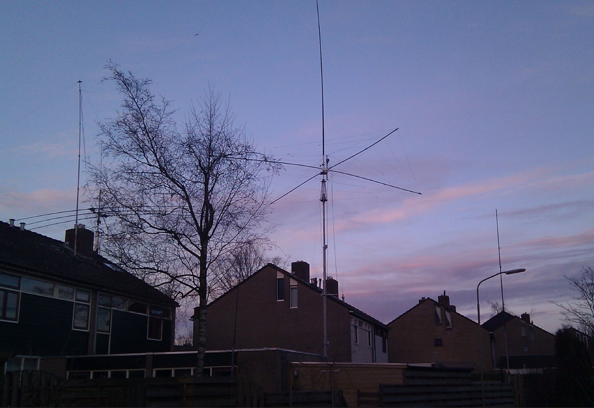 A custom center hub for a Spiderbeam yagi antenna, enabling side-mounting on an existing mast. Challenges included structural instability, limited reach for assembly, and interference with a pre-mounted Spiderpole. A new hub using 40x40mm aluminum tubing provided strength, allowed side assembly, and supported fiberglass pole guy lines. The solution facilitated efficient installation and removal, delivering excellent performance compared to a SteppIR yagi.
 -
 Aluminum telescopic masts and accessories. Discover high-quality telescopic masts and accessories for all applications. Perfect for amateur radio operators, our masts are ideal for fixed or portable antenna setups. Durable, versatile, and made in France.
 -
 VE1ZAC's analysis details the performance of **MFJ927** and **SGC239** autotuners with portable HF vertical antennas, specifically comparing 31 ft and 43 ft configurations. The resource originated from challenges encountered during a Maritime QSO Party roving operation, necessitating a lightweight and easily deployable antenna system. Target bands for the contest included 80, 40, 20, 15, and 10 meters, with a maximum power handling of 100 W CW. The author utilized a 30-foot carbon fiber push-up pole to support a vertical wire element, noting its 2 lb weight and reliability. EZNEC modeling was employed to predict performance, showing favorable results for a 30-foot vertical with elevated radials, particularly on 40 and 20 meters. Feedpoint impedance measurements, taken with an AIM4170C, are presented for various HF bands, both with and without a 41-foot RG6 stub designed to reduce reactance on 80 and 20 meters. The stub significantly improved matching on these bands, easing the tuner's workload. Operational tests revealed issues with the MFJ927's reliability during contest setup, leading to reliance on the K3's internal tuner. The SGC239, tested post-contest, performed flawlessly. A detailed side-by-side comparison covers mechanical aspects, connection options, power bias, impedance range, board quality, and documentation. Modifications to the MFJ927, including a new aluminum case, white paint for heat reduction, and upgraded impedance-measuring resistors, are also described.
 -
 The 2m 7 element Yagi antenna is a perfect beam antenna with 11dB gain and a front-to-back ratio of 20-25 dB. It has seven elements and requires a matching network built of 3/8" aluminum tubing and RG-8 cable. The gamma tube is adjusted to provide the best fit, and the gamma-driven element feeding clamp is tightened. If the beam is vertical, a non-conducting mast is utilized to prevent detuning and skewing of the radiation pattern. For optimal VHF operating, the antenna is installed at a height of 30 feet or higher.
 -
 145 MHz is the target frequency for this 2-meter Skeleton Slot Yagi Stack antenna project. The design focuses on feeding two stacked Yagi antennas using a skeleton slot radiator, which is a unique approach for VHF enthusiasts. The project details the construction process, including the loop tapered matching section for impedance matching, ensuring optimal performance. The use of specific components like the EH789 element holder and MB456 main mast bracket is highlighted, providing clarity on the assembly process. The construction utilizes 20x20 box aluminum bar for durability and precision. Key dimensions, such as the element length (ER-ED4) and main boom spacing (MM123), are meticulously outlined. This attention to detail aids in replicating the antenna design accurately. The downloadable PDF offers comprehensive instructions, making it accessible for amateur radio operators interested in VHF antenna construction. This project is particularly beneficial for those looking to optimize their 2-meter band operations. The inclusion of a skeleton slot radiator and loop tapered matching section demonstrates advanced techniques in antenna design, catering to both intermediate and advanced builders.
 -
 Fully functional weathervane conceals an efficient 2- meter base-station antenna. Your Neighbors and HOA won’t know it’s there and they will love the rooster-vane. The Rooster-Tenna is a covert 2-meter ham radio antenna disguised as a functional weathervane, ensuring seamless integration into residential environments. This improved version features a wide-spaced parallel-fed folded dipole in a compact skeleton slot design. Constructed from aluminum tubing and acrylic supports, it offers omnidirectional, vertically polarized performance suitable for repeater and satellite use. Easy to mount and tune, it achieves a low SWR across the 2m band. With 3D-printable parts available, the Rooster-Tenna blends practicality with stealth, making it an ideal solution for HOA-restricted areas
 -
 Galvanic corrosion, a destructive process triggered by dissimilar metal contact in a corrosive electrolyte, poses a significant threat in antenna manufacturing. With aluminum and stainless steel components commonly involved, unaddressed corrosion can lead to white particle accumulation, causing long-term damage. Awareness of the galvanic series and the application of protective coatings like Alumslip can mitigate this pervasive issue, ensuring a prolonged antenna lifespan.
 -
 The UHF J-Pole antenna described here utilizes an aluminum angle bar and 4mm galvanized threaded rod for its construction, with dimensions based on a previously published design. Assembly involves drilling the angle bar, securing threaded rod sections with nuts, and connecting the coaxial cable via cable lugs, ensuring the braid connects to the shorter element. ROS adjustment is achieved by manipulating nuts approximately **30mm** from the angle bar, allowing for fine-tuning of the impedance match. Once optimal tuning is established, _super glue_ is applied to seal the coaxial cable ends and protect the threaded rod cuts from corrosion, enhancing durability. This project emphasizes rapid realization with common hardware, providing a practical solution for radio amateurs seeking a simple yet effective antenna for the 70cm band.
 -
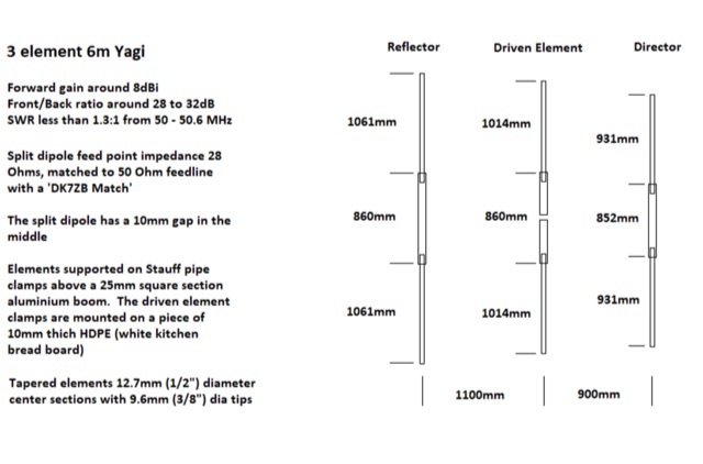 A small Yagi antenna for camper van. It is made of aluminum tubing, breaks down for storage, and works well for communicating with others. He built it in an afternoon and it gets good signal. The antenna is lightweight and can be packed up to fit inside his van while traveling
 -
 Presents the design and construction of a folding 5-element Yagi antenna specifically engineered for 144 MHz portable operation, particularly for VHF contest Rover categories. It details element dimensions, boom construction using ¾-inch pine, and a folding mechanism that reduces the 52-inch boom to 26 inches for transport. The document provides a table with precise element distances and lengths, including a 2.4 mm length correction for solid parasitic elements, and specifies the use of 3/16-inch solid aluminum for parasitic elements and brass tubing for the driven element. It also covers the bent dipole driven element design for impedance matching, balun implementation with Type 31 ferrite beads for common mode current suppression, and weatherproofing for the feed point. The resource includes predicted performance data from 4NEC2 modeling, showing SWR and return loss characteristics, as well as gain and front-to-back ratios at various frequencies across the 2-meter band. It reports a measured SWR of 1.2:1 at 144.2 MHz and 1.5:1 at 147 MHz, corrected for 25 feet of RG-8/M coaxial cable loss. The design offers approximately 1.5 dB more gain than a previous 4-element design, maintaining a decent SWR up to 147 MHz, and was successfully deployed in a winning June 2016 ARRL VHF Contest Rover entry.
 -
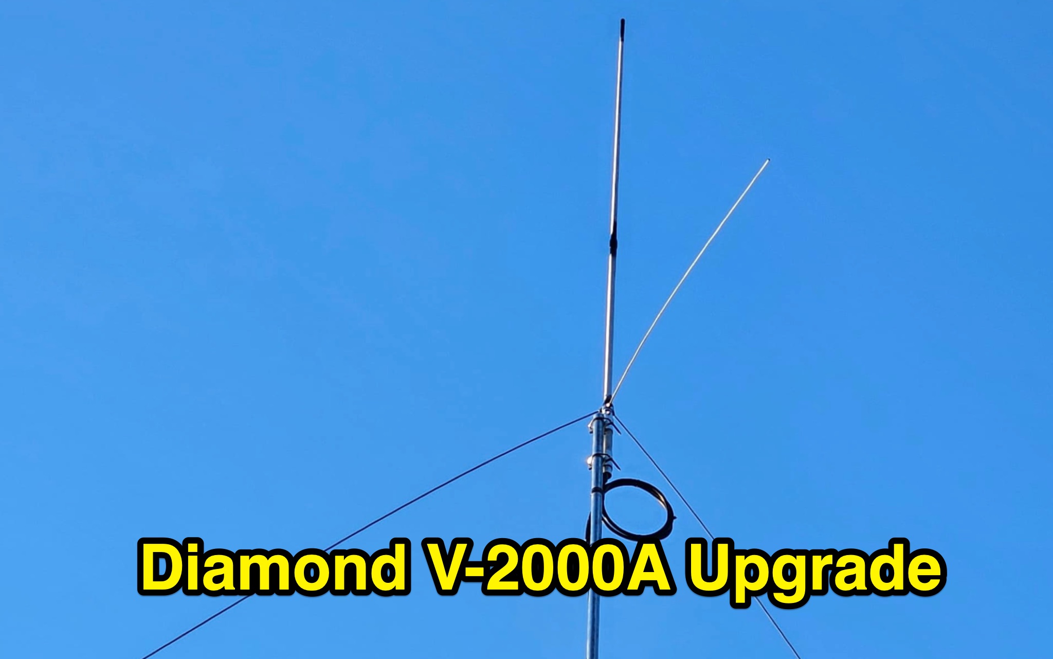 Learn how to enhance the performance of your Diamond V2000A antenna by optimizing the length of the radials. Discover a cost-effective method to create improved radials using simple materials like aluminum tubes and bolts. Explore the benefits of this modification for 6m band, unlocking triband capabilities and better SWR. Find out how a ham radio operator from Europe successfully upgraded their V2000 antenna and achieved impressive results. Save money by DIY-ing your radial enhancements instead of purchasing expensive replacements.
 -
 A common mode choke/balun, essential for mitigating common mode current on antenna feedlines, is detailed in this construction and measurement guide. It utilizes eight Fair-Rite #2643167851 Mix 43 ferrites housed within a Hammond 1598JSGYPBK plastic case, with RG-8X coax cable forming the windings. The document references design principles from Ian White, GM3SEK's article on cost-effective ferrite chokes. Specific construction details include the layout of three coils to minimize inter-coil coupling and methods for securing the ferrites with foam tape. The resource presents comprehensive measured data, including isolation impedance (magnitude, real, and imaginary components), Q factor, inductance, and phase angle across various frequencies. It also covers the choke/balun's coax frequency response and return loss characteristics. Techniques for measuring choking impedance are thoroughly explained, focusing on S21 transmission measurements with a Vector Network Analyzer (VNA) and testing ferrite beads in both S11 and S21 modes. The guide describes a practical setup using an aluminum sheet or baking foil for measurements and outlines the calculation of series impedance from attenuation in a 50-ohm system. Additionally, it details a method for determining the balun's equivalent L and C around resonance by adding a parallel capacitor.
 -
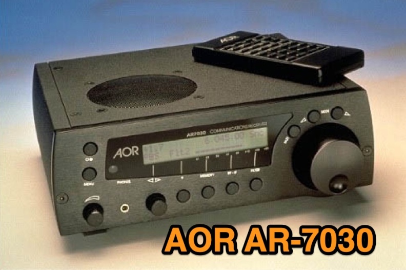 Examines the AOR AR-7030 communications receiver, detailing its technical specifications and operational characteristics. The resource describes its compact design, CNC machined aluminum cabinet, and a frequency range spanning 0-32 MHz. Key features include a ceramic metal cased 4 kHz AM filter, with typical bandwidths of 2.2 kHz, 4.0 kHz, 5.3 kHz, and 9.5 kHz, alongside 400 memory channels and multi-timer functionality. It emphasizes the receiver's high-quality components and a design philosophy focused on reliable performance without superfluous features, making it a dedicated tool for serious listeners. The review assesses the AR-7030's performance within its price class, particularly for **medium wave** and **shortwave** reception. It provides insights into how the receiver's design choices, such as its robust construction and specific filter options, translate into practical listening experiences. The analysis highlights its suitability for users prioritizing signal clarity and operational stability over extensive, complex features, offering a clear perspective on its utility for dedicated DXers and broadcast listeners.
 -
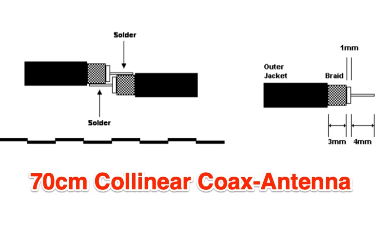 The 9 dB gain 70cm collinear antenna project details the construction of an 8-element array using RG58/U coaxial cable, designed for the 444 MHz band. Each half-wavelength section of RG58/U is precisely calculated, accounting for a velocity factor of 0.66, ensuring optimal resonance and performance. The design incorporates a quarter-wave wire element at the top and a quarter-wave aluminum or copper tube at the bottom, with specific length calculations provided for each component. Construction involves careful cutting and soldering of the coax elements, exposing the center conductor and braid, and tinning the braid for robust connections. The feed point connection to the main RG58/U coax is also thoroughly described, ensuring proper impedance matching for the UHF band. Encased in PVC pipe for weather protection, this homebrew antenna offers a cost-effective solution for amateur radio operators seeking a reliable UHF antenna. The article includes step-by-step instructions, making it accessible for those interested in building their own antennas.