Search results
Query: elements 6
Links: 245 | Categories: 0
-
-
 Presents the DBO274 Citizen Band mailbox, a digital communication hub accessible via HTTP and Telnet, specifically catering to **CB radio** enthusiasts in Germany. This resource outlines its functionality for Packet and other digital emissions on the 11-meter band, a segment often overlooked by traditional amateur radio operators but vital for CB users seeking advanced communication methods. The author, DH8YMB, provides insights into its operation, reflecting practical experience with digital modes in the CB spectrum. The DBO274 serves as a bridge, enabling users to exchange messages and data packets, extending the reach and utility of standard CB transceivers. It represents a localized digital infrastructure, demonstrating how the 27 MHz band can support more than just voice contacts, incorporating elements of early internet-like communication within the CB community. This setup highlights the enduring innovation within the CB realm, adapting technologies like Packet Radio for a different user base. It underscores the versatility of radio communication, even on less conventional bands, for those interested in digital data exchange beyond the typical amateur allocations.
 -
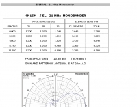
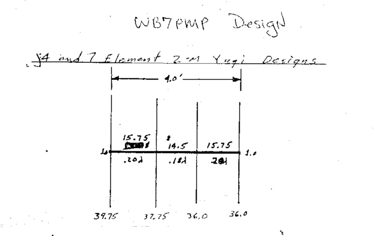 Original drawing and design of a 4 and 7 elements yagi antenna for 50 Mhz
 -
 SimSmith is a highly interactive, real time Smith chart graphing program. Circuits are constructed using drag-n-drop. Load files can be imported from the EZNEC and CocoaNEC antenna simulation software and from the AIM4170 and miniVNApro antenna analyzers. Circuits and load files can be of any size. Key Features: SimSmith is one of the few Smith chart packages which models transmission line losses. SimSmith also allows the description of circuit elements using algebraic equations. SimSmith has only one screen and allows the screen to be resized to increase workspace or readability.
 -
 Collection of different techniques to homebrew PVC yagi antennas, including elements assembling, baluns and chokes, radiator box tips and tricks by dk7zb
 -
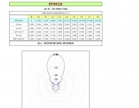
 This document details the design and construction of a Vinecom 6N4 dual-band Yagi antenna for the 50MHz (6-meter) and 70MHz (4-meter) amateur radio bands. The antenna features 9 total elements (4 elements for 50MHz, 5 elements for 70MHz) on a 4.236-meter aluminum boom. Computer simulations using MMANA software predict 7.21 dBd gain on both bands with front-to-back ratios of 16.01dB (6m) and 15.37dB (4m). The design uses 12.7mm diameter elements mounted on a 32mm square boom, weighing 5.7kg total. Practical measurements with an MFJ-269 analyzer confirmed good SWR performance across both bands after element length adjustments.
 -
 YF1AR multiband vertical antenna, based on orginal concept by VE7BS. Consist of 6 vertical elements and 6 base radials with a single 50 Ohm feed line.
 -

-
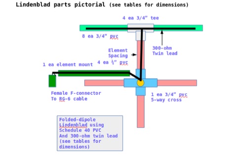 This document contains the detailed instructions to build a homemade lindenblad antenna using a twin-lead as dipole elements. This document contains 9 pages and includes a detailed construction sequence and some drawings to build this antenna for UHF and VHF ham radio bands
 -
-
 Utility program to verify, merge, and sort standard 2-line orbital elements files
 -
-
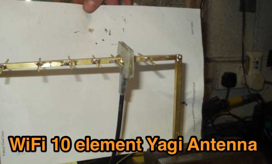 A DIY project of a WiFi 10 elements Yagi antenna
 -
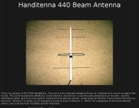 A 4 elements handitenna for 70 cm band. This is my version of the K5OE Handitenna. This one is a four Element instead of three, as I had less of a crunch on space than he did. The 1st three elements (Reflector, Driven Element, and Director 1) are the same dimensions as his were.
 -
 A 70cm and 2m 6 elements yagi antenna plan based on the IEEE Transactions on Antennas and Propagation
 -
 Operating on the amateur radio bands, DXers rely on timely information to chase rare contacts. This resource offers a specialized web interface for accessing DX cluster data, specifically designed for mobile phone displays. It presents real-time **DX spots** in a compact, easy-to-read format, stripping away extraneous elements often found on traditional cluster interfaces. The core functionality focuses on delivering essential spotting information—callsign, frequency, mode, and comments—without requiring complex navigation or excessive data loading, which is crucial for mobile data usage. The utility of this mobile-first design becomes apparent when operating portable or away from a shack. Unlike full-featured _telnet clusters_ or web-based aggregators, DXLite prioritizes quick access and readability on small screens. The interface displays a continuous stream of spots, allowing operators to rapidly identify potential DX opportunities across various bands. Its minimalist approach ensures fast loading times and efficient data consumption, making it a practical tool for on-the-go DXing and contesting.
 -
 Demonstrates the construction of a 144 MHz turnstile antenna, detailing its design for omnidirectional, horizontally polarized VHF operation. The resource outlines the physical dimensions and materials required, including specific lengths for the radiating elements and the use of _RG-58_ coaxial cable for phasing. It covers the assembly process, emphasizing the critical spacing and connection points to achieve the desired radiation pattern and impedance matching for the _2-meter band_. The article presents measured _SWR_ performance across the 144-146 MHz segment, showing a low SWR of 1.2:1 at 144.5 MHz, which is suitable for general VHF use. It compares the turnstile's performance to a 9-element Yagi, noting the turnstile's advantage in providing consistent signal strength from all directions without requiring a rotator. Practical application for local FM simplex and repeater operations is implied, offering a simple yet effective antenna solution for fixed or portable stations.
 -
 A simple and awesome wire monoband antenna, very usefull for portable and dxpeditions usage, consist of two elements, a driver and the reflector. This endfed halfwave gives a very low take off angle and is very suited for chasing DX.
 -
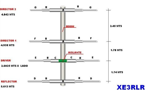
 The resource presents a detailed schematic for constructing a dual-band vertical antenna, specifically designed for operation on the 2-meter and 70-centimeter amateur radio bands. It illustrates the physical layout, critical dimensions, and component placement necessary for successful replication. Key elements such as the radiating elements, phasing sections, and feed point are clearly depicted, providing a visual guide for radio amateurs undertaking a homebrew antenna project. The diagram specifies the lengths for the VHF and UHF sections, indicating how these elements are integrated to achieve dual-band functionality from a single coaxial feedline. It also implies the use of common materials readily available to most experimenters, focusing on simplicity and effectiveness in its design. The visual format of a GIF image ensures direct access to the construction details without requiring extensive textual interpretation. This schematic serves as a practical reference for hams interested in building a compact, efficient vertical antenna for local and regional FM communications, offering a proven design for immediate implementation.
 -
 This is a plan for a 10 elements yagi antenna for 50 mhz
 -
 Phased antennas elements use radiated fields from multiple elements to produce nulls.
 -
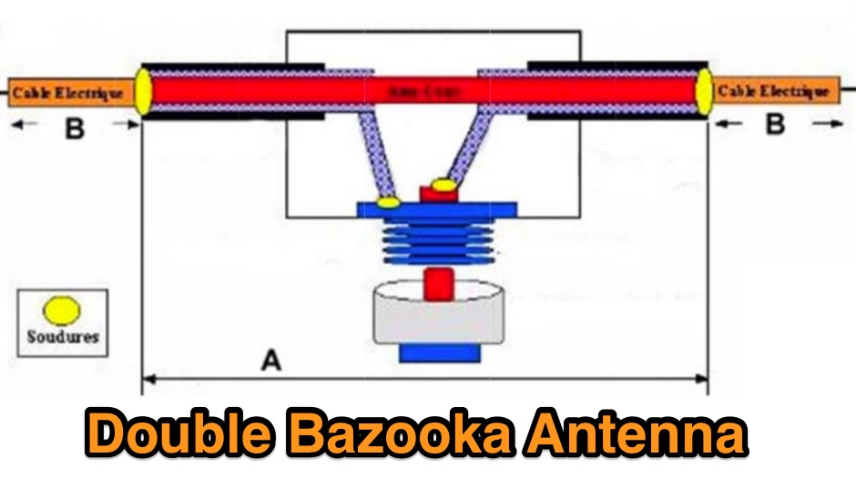 A page in french dedicated to the double bazooka antenna, with a short history of this antenna model and main characteristics including a comparison versus the dipole antenna and formulas to determine elements size.
 -
 Demonstrates the construction and implementation of a **two-element phased vertical array** for 40 meters, utilizing _Christman phasing_ techniques. The author, W4NFR, details the process from building individual 1/4-wave aluminum verticals to integrating them into a phased system. The resource covers antenna spacing of 32 feet, elevated radial design, and the critical steps for tuning each vertical to achieve a 1.1:1 SWR before combining them. It also provides insights into calculating precise coax lengths for feedlines and the phasing delay line, emphasizing the use of an MFJ-269 Antenna Analyzer for verification. The finished system exhibits good front-to-back nulls, with an overall SWR ranging from 1.6:1 to 2.2:1, which is managed by an antenna tuner. The project includes detailed photos of the relay box, showing 12 VDC relays capable of handling 5KV, and the control box in the shack for switching between three different antenna pattern configurations. Static bleed-off chokes are incorporated for protection, and the construction emphasizes robust weatherproofing for outdoor elements.
 -
 The Elecraft K2 transceiver requires specific modifications for optimal soundcard digital mode operation, particularly for PSK31. The original article, circa 2001, details initial challenges with manual PTT and speech compression settings. A key modification involves adding headphone audio and a compression disable signal to the K2's microphone jack, utilizing pins 4 and 5. The **COMP0** signal, active low, is shorted to ground via a non-inverting open collector switch circuit, comprising two resistors and two transistors, mounted on the SSB board near U3. This circuit provides effective control of an analog signal line with good noise immunity. The switchbox itself repurposes a computer COM port switch, using only two of its original connectors and four of the nine poles. It integrates a microphone preamplifier, a PTT circuit built with 'flying leads' construction, and RCA jacks for soundcard connections. A trimpot adjusts the audio drive to the K2. The central DB9 connector links to the K2's mic connector via a shielded RS232 serial cable, ensuring proper grounding and signal routing. An external footswitch PTT jack is also included. Further enhancements include a **noise-canceling microphone** preamp based on a QST December 2000 article, adapted for Heil mic elements. This preamp, built with pseudo-Manhattan style construction, provides a gain of approximately 2 by changing emitter resistors (R9 and R16) from 680 ohms to 330 ohms. A 10-ohm series resistor and 47 µF capacitor on the +5V supply mitigate noise spikes.
 -
 The design and feeding of driven elements for VHF/UHF Yagi antennas , modeling, observations and some case studies by Graham Daubney F/G8MBI
 -

-
 A 5 elements homemade DK7ZB yagi antenna for 4 meters band based on a 50MHz TONNA
 -
 Demonstrates the adaptation and construction of a 7-element DK7ZB Yagi antenna for the 4-meter band (70 MHz), utilizing components from a defunct 2-meter CUE DEE Yagi. The resource details the modifications made to the original DK7ZB design to fit the shorter CUE DEE boom length, specifically adjusting element lengths for 6mm rod elements while reusing existing mounting holes for the reflector and last director. It provides precise element lengths for the reflector, dipole (12mm aluminum tube), and five directors, along with a note on cutting elements for transport. The article includes a 4NEC2 simulation file for performance analysis and an SWR plot, confirming the antenna's electrical characteristics. It also specifies the calculation for the quarter-wavelength matching cable using SAT752F coaxial cable, resulting in a 909mm length. Practical application is shown with the finished antenna in operation at JO20XC, listing several activated Maidenhead squares such as JO56PA and JP40KS, validating its effectiveness for portable 70 MHz operations.
 -
 This PDF document details the construction of a **70 MHz** Big Wheel antenna, a horizontally polarized omnidirectional array. The design utilizes three full-wave loops, each approximately **2160 mm** in diameter, arranged in a triangular configuration. The resource provides mechanical dimensions for the antenna elements and a comprehensive bill of materials, specifying component quantities and types, such as M8 stainless steel bolts, 15x15x1.5 mm square aluminum tubing for spacers, and 8 mm aluminum rod for the arcs. The central hub is constructed from two 160x160x8 mm aluminum plates, with four 40 mm long polyamide insulators supporting the radiating elements. The feed system incorporates a 50 mm diameter aluminum pipe for mounting and a matching stub constructed from a 120x20x2 mm aluminum sheet, connected via M8x10 mm bolts. The resource includes a diagram illustrating the mechanical dimensions and assembly points, including the N-connector fixing point and the center conductor attachment. The project was published on May 25, 2011, by Peter OE5MPL and Rudi OE5VRL. DXZone Focus: PDF | 70 MHz Big Wheel | Mechanical Dimensions | **2160 mm** loop diameter
 -
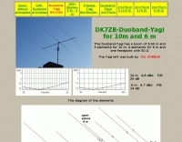 This Duoband-Yagi has a boom of 3.60 m and 3 elements for 10 m 4 elements for 6 m and one feedpoint with 50 Ohm
 -
-
 Article describing how to homebrew a yagi antenna for 50 MHz, includes plans for a four and five elements yagi beam and details how how match impedence with a gamma match
 -
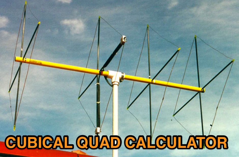 An online javascript calculator for cubical quad antennas, simply input the resonating frequency to calculcate up to a five element quad antenna. This quad antenna calculator let you determine the total length of each element and spacing among elements.
 -
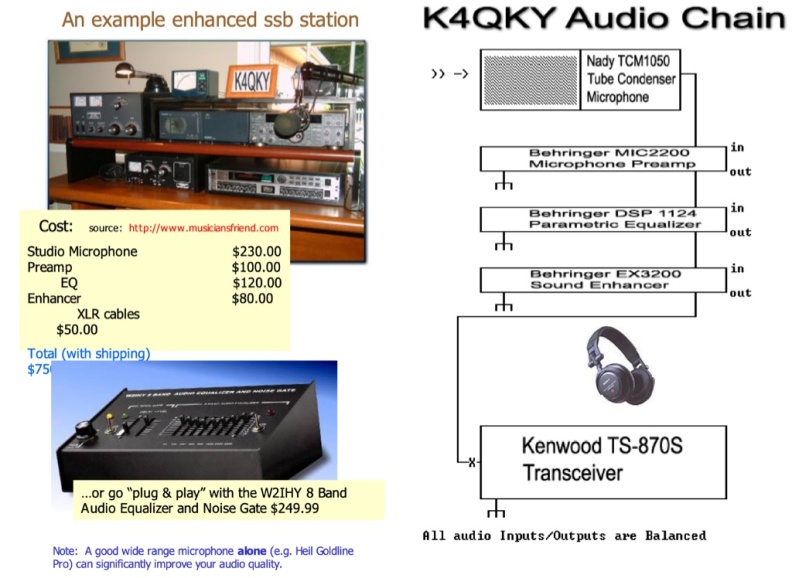 Enhanced SSB Audio (ESSB) is a specialized operating mode that extends the capabilities of traditional Single Sideband (SSB) voice transmissions. This presentation by K4QKY delves into the technical aspects of ESSB, discussing its advantages and the ongoing debates within the ham radio community regarding audio quality and bandwidth usage. ESSB aims to provide clearer and more natural-sounding audio, which can enhance the overall communication experience for operators. The presentation covers various topics, including microphone selection, audio processing techniques, and the importance of proper equalization. It also addresses the controversies surrounding ESSB, such as the potential for interference and the debate over whether it strays too far from traditional SSB practices. By understanding these elements, amateur radio operators can make informed decisions about their audio setups and contribute to discussions about the future of SSB operations.
 -
 A homemade 10 element Yagi Beam Antenna for 50 Mhz by Rod Mackintosh, a NBS Yagi on a 13.2 metre boom.
 -
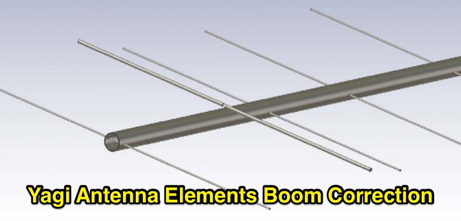 Dragoslav Dobricic, YU1AW antennex article on influence of Boom on frequency performance and how compensate it
 -
 In this PDF article Zack Lau describe how to homebrew a four element yagi beam antenna for 50 MHz band, including how to build mounting blocks and tubing clamps to hold elements.
 -
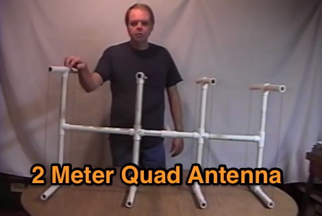 A four elements quad antenna for 144 MHz made with PVC pipes
 -
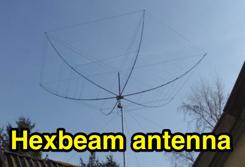 An HexBeam antenna project, a 2 full elements on six bands
 -
 A 5 element yagi beam antenna for ten meters band with full dimentsions, eznec file and coax match informations for 50 ohms feed line
 -
 An homebrew project for a 4 elements yagi monoband antenna for the 10 meters by 9M2MSO
 -
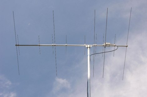
 An high gain long yagi antenna, seven elements, for six meters band
 -
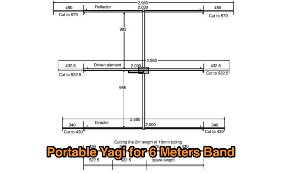 A portable three element 6M yagi for less than twenty pounds
 -
 Designing and constructing portable wire antennas for HF operations, this resource explores several configurations including the _foldback dipole_ for space-constrained setups and an inductively shortened dual-band dipole for 20m and 40m. It details the calculation of inductance for shortened elements, providing a Visual Basic 6.0 program screenshot that illustrates determining coil parameters like turns and length for a **25.5 uH** inductor. The document emphasizes practical considerations such as adjusting wire lengths for optimal SWR, noting that a dual-band dipole achieved SWR below 2:1 on both 20m and 40m, with careful adjustment bringing it under 1.5:1. Further, the resource describes a half-wave antenna matched with a coaxial stub, a method often referred to as the _Fuchskreis_ in German amateur radio circles, to transform the high feedpoint impedance to 50 Ohms. This monoband solution, for a 20m application, uses a stub length of **2.98m** (0.216 lambda multiplied by coax velocity factor) and a shorted stub of approximately 48cm. The coaxial stub design is highlighted for its resilience to ground proximity, allowing it to be rolled up or laid on the ground with minimal SWR impact, making it highly suitable for portable QRP operations.
 -
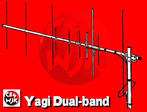
 Yagi with 5 Elements on 2 m, 8 Elements on 70cm and one Feedpoint by DK7ZB
 -
 Hi-Z Antennas offers specialized high-impedance receiving systems, primarily focusing on phased vertical arrays for HF reception. Their product line includes preamplifiers designed for shortened vertical antennas, featuring optimized 15dB gain and array-matched characteristics. These components are engineered to enhance weak signal reception and improve signal-to-noise ratio across the HF spectrum. The company provides controllers for managing multiple vertical elements in a phased array configuration, enabling directional reception patterns. These systems are particularly effective for mitigating local noise and interference, a common challenge in urban and suburban operating environments. Specific offerings include solutions for 160-meter and 80-meter bands, addressing the unique requirements of low-band DXing. Technical details often reference components like the 2N3866 transistor in preamp designs and discuss concepts such as out-of-band attenuation. The focus remains on optimizing receiving antenna performance through impedance matching and active amplification, rather than transmit capabilities.
 -
 Based on a simple project based on a 2 elements Yagi for 20m band, and then becomed a triband yagi with a open-sleeve feed system
 -
 50MHz Collapsible 2 Element Mini Beam antenna, an overview the development of the 6MBA.
 -
 A 4 elements Yagi-Uda antenna for 144.3 MHz plan with dimensions and yagimax dimension calculation
 -
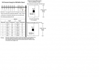
 50 MHz extended 6-7 element ZX-Yagi antenna. Dimensions for the 7 elements and information on performance of a 2 stacked antennas featuring a total max gain of 20.8 dBi