Search results
Query: low power
Links: 244 | Categories: 6
-
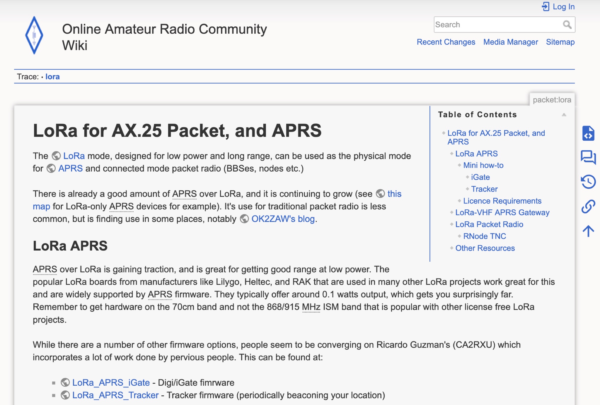 Learn how LoRa mode can be used for APRS and connected mode packet radio, offering low power and long-range communication. Discover the growing popularity of LoRa-only APRS devices and the use of LoRa boards from manufacturers like Lilygo, Heltec, and RAK. Find out about firmware options like Ricardo Guzman's CA2RXU firmware, which incorporates previous work and offers KISS for external APRS clients. Explore LoRa APRS frequency and modulation settings in the UK, and consider adding CA2RXU firmware to lora-aprs.live for more radio-specific information. Dive into the world of LoRa technology for ham radio operators and experiment with different firmware options.
 -
 The Wanted Alive (TWA) by OH2BUA is an online DX cluster service specifically tailored for digital mode enthusiasts, presenting real-time DX spots with a unique ranking system. Unlike traditional clusters, TWA sorts spots by decreasing DXCC most-wanted ranking, allowing operators to prioritize rare entities. It integrates data from various sources, including PSK Reporter and RBN, to provide a comprehensive view of current propagation conditions for modes like FT8, FT4, and JS8. This approach helps DXers quickly identify and pursue high-value contacts, optimizing their time on the air. OH2BUA's TWA provides a practical application for serious DXers by filtering the noise and highlighting the most sought-after DXCC entities. The service's focus on digital modes reflects the growing popularity of these efficient, low-power communication methods, offering a specialized tool that complements general-purpose DX clusters. By presenting propagation information through the lens of DXCC rarity, TWA assists operators in achieving DXCC awards and improving their overall DXing efficiency, particularly during contests or limited operating windows.
 -
 The DIY Power Meter project utilizes the _INA226_ high-side power monitoring chip, paired with an ATtiny85 microcontroller, to measure voltage, current, and power, displaying the results on a 128x32 OLED screen. The INA226 communicates via an I2C interface and is programmed with a calibration factor based on the shunt resistance and current register LSB. The project is designed to handle a maximum current of 500mA using a 0.16ohm shunt resistor, which can be adjusted to a 0.2ohm resistor, reducing the full-scale current range to 409mA with a resolution of **12.5uA**. The shunt resistor dissipates only 33mW at maximum current, making 1/4 watt resistors suitable for the setup. The PowerMeter.ino sketch configures the shunt resistance and maximum design current, automatically calculating the calibration factor. The project can be prototyped on a breadboard using an Arduino Uno, employing the Wire library for INA226 and OLED communication, and the u8g2lib library for the OLED display. For the ATtiny85 version, the Adafruit-TinyWireM and Tiny4kOLED libraries are used. The power meter is independently powered by a 3V CR2032 cell, with power switching options including manual switches or DC switched jacks. The low-side n-channel MOSFET switch configuration is tested but introduces voltage drop issues, making manual switching a more reliable option until a suitable DC switched jack is found. DXZone Technical Profile: INA226 | ATtiny85 | OLED Display | Power Meter
 -
 Integrating a _Software Defined Radio_ (SDR) into an existing ham radio setup involves connecting it with a standard transceiver (TRX), power amplifier (PA), and antennas. The core component is a splitter box that facilitates the connection between the TRX and the SDR, allowing for simultaneous operation without modifying existing equipment. In receive mode, the splitter ties the antenna inputs of both the TRX and a direct conversion receiver (DC RX) together. During transmission, the DC RX input is grounded via a fast telecom relay controlled by the transceiver's -SEND signal, incorporating a 10ms delay for safety. The splitter box includes a 3.7 dB input attenuator for impedance matching and acts as a protective fuse for the DC RX input. Ground loops are mitigated using common mode balun transformers, while the DC RX input is insulated with a broadband transformer. An audio switch box complements the setup, enabling users to listen to either the main transceiver, the SDR output, or both simultaneously. This configuration ensures noise immunity and safety, with the splitter housed in a screened box made from PCB material. On-air tests, such as the CQ WW 160m CW DX Contest, demonstrate the system's effectiveness, showcasing the SDR's ability to handle crowded band conditions with superior selectivity and dynamic range. The SDR's narrow bandwidth filters and waterfall display provide significant advantages, allowing operators to detect weak signals amidst strong interference. The integration of SDR with conventional radios offers enhanced operational flexibility and performance in challenging environments.
 -
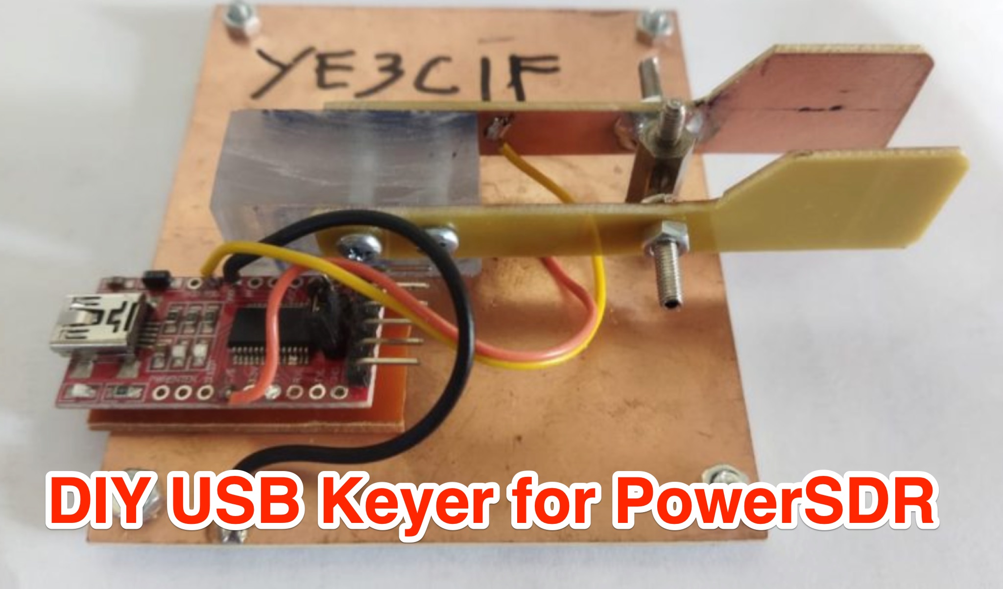 Learn how to create a USB Keyer for PowerSDR to enhance your CW experience. This article provides a step-by-step guide using affordable materials like a USB to TTL Module (FT232RTL) and a Keyer iambic. The tutorial includes a detailed wiring diagram and instructions for configuring the Keyer in the PowerSDR menu. The author also shares a helpful video demonstration to ensure smooth operation. Whether you're a seasoned ham operator or new to CW, this DIY project can improve your radio setup. Follow these instructions to build your USB Keyer and elevate your PowerSDR experience.
 -
 The POCKET TUNER V1.1 is a highly compact HF T-Match antenna tuner designed for QRPp and QRP portable operations. With a credit card-sized form factor, it is tailored for low-power setups, supporting HF bands from 10m to 40m. The tuner features a unique design using rotary switches for precise capacitor adjustments, allowing tuning in small increments. Its inductance selection is optimized for various bands, ensuring efficient performance. Equipped with a resistive tuning indicator, it protects the transmitter by reducing SWR during adjustments. This versatile and portable tuner is ideal for field operations, enabling efficient antenna matching for low-power rigs.
 -
 This project presents a compact QRP SWR meter featuring a 0.96" OLED display (128x64 pixels) for high-contrast visibility, updated with software fixes for display compatibility, improved low-power performance, and support for ATtiny45/85 microprocessors. A 1.3" OLED version accommodates visibility needs. Designed for HF QRP transmitters (3-15W), it uses a Breune coupler with germanium diodes for accurate SWR measurement. Powered by a AAA battery, the meter offers a standalone solution for impedance matching, with a 3D-printed enclosure enhancing portability.
 -
 If your FT-817 has stopped powering up from the internal battery but works from external power, then maybe the internal battery fuse has blown. There is a small PCB mounted fuse to protect the battery and radio. This fuse can blow, if it does your radio will not work from battery power. This page will describe how to test the fuse and describe how to make a repair.
 -
 This article discusses the evolution of portable amateur radio operations, focusing on optimizing backpack-carried equipment for outdoor use. The author shares his journey from using wheeled carts to developing an innovative backpack-mounted antenna system, emphasizing the transition from high-power (QRO) to low-power (QRP) operations to reduce weight. The piece details practical solutions for antenna mounting, equipment selection, and portable operations in challenging terrain, particularly along Ontario's Niagara Escarpment. The author's approach prioritizes mobility and functionality while maintaining effective radio communications in remote locations.
 -
 This software enables remote monitoring of the Kenwood TS-590SG HF transceiver. Based on a lightweight, text-based monitor was developed using Python and ncurses. It connects via rigctld, displaying key metrics like frequency, power, SWR, and TX/RX state with minimal data usage. Ideal for low-bandwidth remote operation, it works over SSH or mobile data. The software is open-source under GPL v3.
 -
 Demonstrates practical **rules of thumb** for selecting and utilizing ferrites and coils in amateur radio projects, particularly for RF applications up to 30 MHz. It addresses common challenges like determining appropriate ferrite grades and estimating L/C values without precise specifications. The resource details the author's experience with readily available grey ferrites, noting their suitability for HF work, and provides guidance on constructing **baluns** and RF chokes, balancing inductance for lower frequencies against inter-wire capacitance for higher frequencies. It also outlines a method for estimating power handling based on ferrite weight, suggesting a 1-gram ferrite can manage over 2 Watts, and offers a technique for evaluating unknown ferrites by winding 10 turns and measuring resonance with a 1 nF capacitor. This approach emphasizes a hands-on, iterative method for balun winding and adjustment, allowing operators to quickly approximate component values. The article compares the characteristics of ferrite-cored coils with air-cored coils, highlighting the reduced pickup and radiation of ferrite designs. It refines the air-coil estimation method for frequencies between 2.5 MHz and 10 MHz and provides a scaling factor for frequencies outside this range, aiming to get operators into the correct general area for their designs. The author's standardized ferrite choice (RND Components 165-00182) is presented as a practical example for reproducible projects.
 -
 This article demonstrates how to convert an existing tower into a dual-band vertical antenna for 80- and 160-meter DX operation. Using EZNEC modeling and practical design principles, the authors achieved a low-profile, efficient setup with a single coax feed line, no moving parts, and optimal radiation patterns. The system integrates an 80-meter vertical wire and a 160-meter shunt-fed gamma match for simultaneous operation. Detailed construction insights, including feed system and capacitor configurations, offer a reliable, full-legal-power solution.
 -
 This page discusses the potential risks and safety concerns related to antenna installations for ham radio operators. It emphasizes the importance of following electrical codes and regulations to prevent property damage, injuries, or even loss of life. The author shares personal experiences and advises against using trees for antenna support near power lines. The content serves as a cautionary resource for hams planning antenna setups to ensure safety and compliance with regulations.
 -
 The CW keyer with memories, inspired by SOTA activities, features three on-the-fly programmable memories for hands-free operation during logging or specific calls. Designed for low power consumption, it uses AAA batteries and an Arduino Mini, optimized for minimal energy use with a sleep function. The compact design fits in a small TEKO box, with a printed circuit board for easy assembly. The keyer includes customizable software for various CW modes and settings, programmable via paddles and command mode. It's an efficient, portable solution for amateur radio enthusiasts seeking enhanced CW functionality.
 -
 A versatile digital VFO design utilizing the Silicon Labs Si5351a oscillator chip and Nokia 5110/3310 graphics LCD display, operating from 1-160MHz with dual VFO capability. This microcontroller-based system, powered by an ATmega328 processor, features rotary encoder tuning, selectable step sizes, RIT control, and comprehensive band memory functions. Drawing less than 40mA at 3.3V, it significantly improves upon previous DDS designs' power consumption while offering advanced features like S-meter display, VFO lock, and programmable BFO/CIO offsets. The design achieves flexible functionality through simple hardware implementation and efficient software architecture, making it particularly suitable for QRP and portable amateur radio applications.
 -
 Tubes are a dying technology. All modern transmitters, even high power ones, do work with transistors and other semiconductors. But many fondly remember their first homebrew transmitter and its hard to forget warm glow of a vacuum tube. The Station QRP website is especially for you to come into touch with tube technology. This site is all about handcrafted QRP AM tube transmitters.
 -
 KISS703 is a 703 Hz narrowband digital mode for amateur radio, designed for simple, low-power operation without computers. A 500 Hz pilot tone ensures frequency alignment, replaced by unique tones for 37 symbols (letters, numbers, space). Built from common discrete components, it draws about 40 mA at 12 V, ideal for SOTA/IOTA use. The receiver uses amplification, wave shaping, and a pulse-counting frequency meter for manual decoding via a calibrated meter. Transmitter and receiver calibration involves marking meter positions for each tone, enabling fully self-contained messaging with minimal hardware in portable or fixed operations.
 -
 The RXC70/10 is a sensitive 70 MHz to 10-meterband converter using the Philips SA602 mixer IC. It operates with high stability and low noise, converting 70–72 MHz signals to 28–30 MHz for general coverage receivers. The compact, low-power design (15mA) supports various modulations and uses. Its versatility makes it suitable for amateur radio applications with proper tuning and antenna setup.
 -
 A dual insert microphone design for the Icom IC-7300 transceiver utilizes a **Besson BZ2400 M4 Rocking Armature** insert for frequencies from 500 Hz to 3 kHz, exhibiting a rising response of approximately 11 dB. A generic Electret Condenser insert, powered by the transceiver's microphone line, covers the low-frequency range from 100 Hz to 500 Hz. A Low Pass Filter is incorporated after the Electret insert to prevent frequency overlap, and a pre-set potentiometer (VR1) adjusts the low-frequency response, balancing the output of both inserts. The design emphasizes a "Close Talking" arrangement and addresses audio "colorization" by housing the Besson insert in a thick rubber holder with a foam boot, separate from the circuitry, with the Electret insert also wrapped in a foam boot. Critical importance is placed on using the correct BZ2400 M4 insert with 12 holes in its face plate. The frequency response table for the BZ2400 M4 insert shows 0 dB at 500 Hz, rising to +11 dB at 3000 Hz, while the Electret insert with the Low Pass Filter provides 0 dB at 100 Hz, rolling off to -9 dB at 500 Hz and -50 dB at 3000 Hz. This combination ensures a broad, balanced audio spectrum for SSB operation. The project includes a circuit diagram, a comprehensive parts list detailing components like a 1 Henry iron-cored inductor (L1) and various capacitors, and a board layout within the metal tube. The completed unit provides a tailored audio profile for the IC-7300, enhancing transmit audio quality.
 -
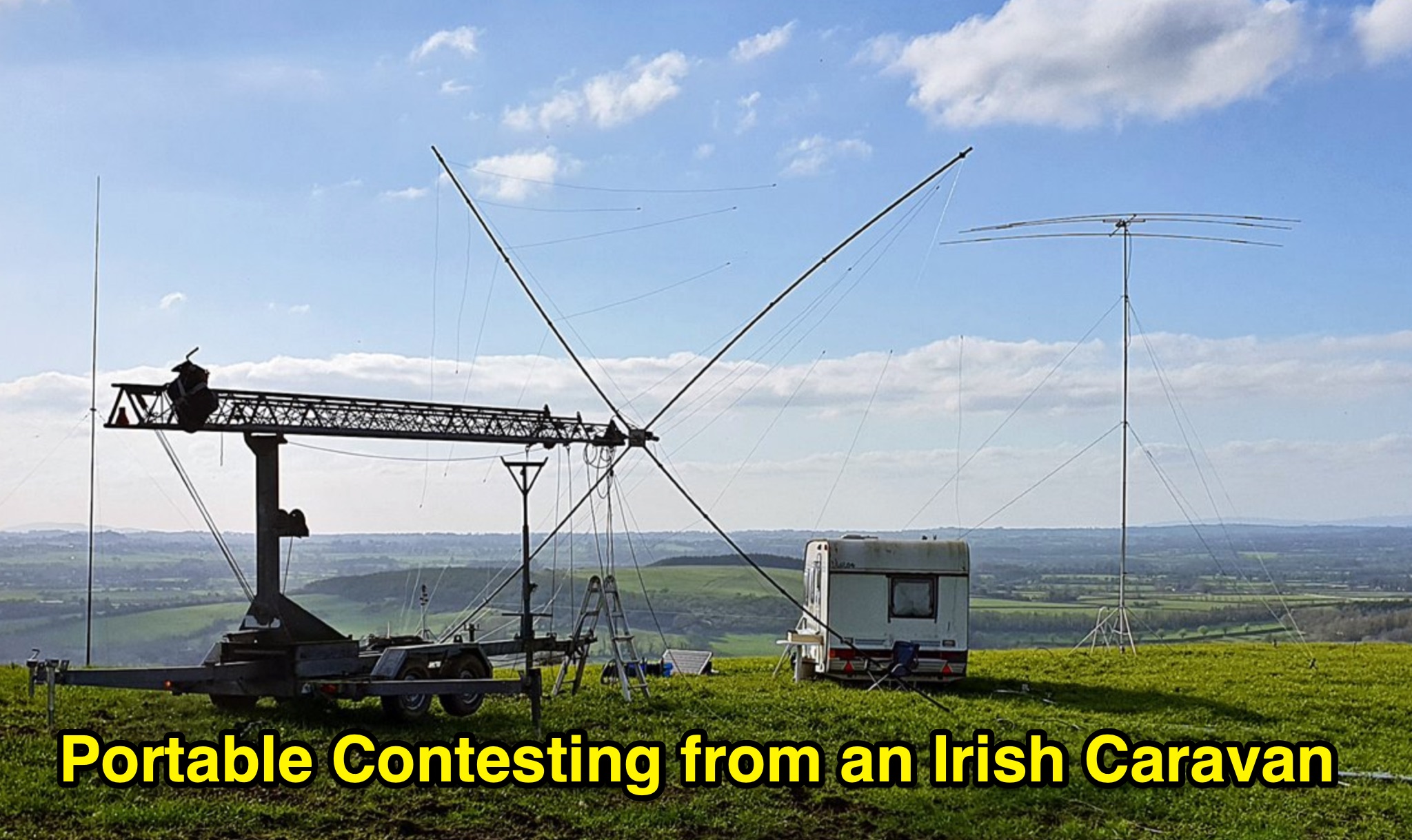 This blog chronicles over a decade of portable HF contesting from rural Ireland (2008–2019) by Olivier, operating under callsigns EI/ON4EI, EI8GQB, EI1A, and EI7T. Using only green energy from a caravan, he achieved top-tier results in major international contests—including 1st World in the 2018 IARU HF Championship (SSB LP) and multiple 1st-place finishes in CQ WW and CQ WPX SSB Europe. Operating in the demanding Single Operator All Band Low Power and SO2R categories, he deployed up to five antennas across five bands, often in remote or emergency-style conditions. The narrative blends technical detail, fieldcraft, and personal reflection, documenting triumphs, setbacks (including carbon monoxide poisoning), and the logistical challenges of sustainable portable operation—culminating in his decision to transition to team-based contesting and future DXpeditions.
 -
 The Olivia digital mode, a **Multi-Frequency Shift Keying (MFSK)** radioteletype protocol, is specifically engineered for robust communication under difficult propagation conditions on shortwave radio bands from 3 MHz to 30 MHz. Developed by Pawel Jalocha in 2003, Olivia signals can be decoded even when the noise amplitude exceeds the digital signal by over ten times, making it highly effective for transmitting ASCII characters across noisy channels with significant fading and propagation phasing. Early on-the-air tests by Fred OH/DK4ZC and Les VK2DSG on the Europe-Australia 20-meter path demonstrated intercontinental contacts with as little as one-watt RF power under favorable conditions. Common Olivia modes are designated as X/Y, where X represents the number of tones and Y is the bandwidth in Hertz, with examples including 8/250, 16/500, and 32/1000. The resource clarifies that Olivia, unlike some other digital modes, produces a constant envelope, allowing RF power amplifiers to achieve greater conversion efficiencies and making it less prone to non-linearity. Operators are advised that **Automatic Level Control (ALC)** can be set higher than no meter movement for MFSK modulation, as long as it's not driven past its high limit, contrary to common misinformation about other digital modes. The Olivia community encourages voluntary channelization on suggested calling frequencies, such as 14.0725 MHz for 8/250, to facilitate initial contacts, especially for signals below the noise floor. The Olivia Digital DXers Club provides links to Groups.io, Facebook, and Discord for community engagement and offers details on QSO parties.
 -
 Twenty 1-watt carbon film resistors are configured in parallel to construct a 50-ohm **dummy load** for amateur radio applications. The design incorporates a heatsink for thermal dissipation and an **SO-239 connector** for RF input, making it suitable for QRP operations. This budget-friendly project details component selection, soldering techniques, and mounting procedures, achieving a continuous power rating of 10 watts and intermittent handling of up to 100 watts across HF and VHF frequency ranges. The resource provides a step-by-step guide for assembly. This construction offers an economical solution for essential shack tasks such as antenna tuning, transmitter testing, and SWR meter calibration without radiating an RF signal. The utilization of readily available components significantly reduces the overall build cost compared to commercial alternatives, providing radio amateurs with a functional and reliable test accessory. While specific VSWR measurements are not provided, the design prioritizes practical utility for low-power transceiver diagnostics and general RF experimentation.
 -
 The project details the construction of a GM3OXX OXO transmitter, designed to accommodate **FT-243 crystals** using 3D-printed FX-243 holders from John KC9ON. It presents specific frequency adjustments, noting a 7030 KHz HC-49/s crystal could be tuned from 7029.8 KHz to 7031.7 KHz with an internal 45pF trimmer capacitor. The build incorporates a modified keying circuit to prevent oscillator run-on key-up and includes a TX/RX switch for sidetone via a connected receiver, with the transmitter output routed to a dummy load on receive. Practical construction aspects are thoroughly covered, including the process of cutting a rectangular opening in a diecast enclosure for the FT-243 socket and the selection of a **low-pass filter** (LPF) based on the QRP Labs kit, derived from the W3NQN design. The author achieved approximately 800mW output power from a 14.75V supply, measured with an NM0S QRPoMeter, using a 16.5-ohm emitter resistor in the 2N3866 final stage. The article also touches upon the potential for frequency agility across the 40M band using multiple FX-243 units with various crystals. The narrative includes a brief diversion into Bob W3BBO's recent homebrew projects, such as his Ugly Weekender MK II transceiver, highlighting the enduring appeal of classic QRP designs. The author reflects on the personal satisfaction derived from building RF-generating equipment, irrespective of DX achievements, and shares experiences of making local contacts with the 800mW OXO transmitter on 40 meters.
 -
 This article describes the implementation and testing of a low-power GPS tracker using LoRa technology in the 433MHz amateur band. The system, built with AIThinker RA-02 modules and Arduino controllers, demonstrated successful communication over non-line-of-sight distances up to 5km. Operating with a 125kHz bandwidth and spreading factor of 11, the tracker achieves a data rate of 500 bits/sec. Powered by a LiPo cell with power-saving features, the final compact design operates for approximately 1.5 weeks between charges with 3-minute reporting intervals, consuming just over 1mA in idle mode.
 -
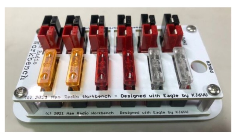 The **5-Port 12 Volt DC Power Strip Kit (Rev 4)** offers a practical solution for managing shack power distribution, providing one input and five fused outputs. All connections utilize the ubiquitous Anderson PowerPole connectors, a standard for many amateur radio operators, ensuring a clean, organized, and safe way to power multiple 12 VDC transceivers and accessories from a single source. This design mitigates the common issue of tangled wires and overloaded connections in a typical ham shack. Rated for a maximum current of 20 Amps at 12 VDC, the strip incorporates an integrated LED to indicate when external power is applied. Each output is individually fused, a critical safety feature that protects connected equipment from overcurrent conditions without affecting other devices on the strip. This level of protection is essential for preserving sensitive radio gear during operation. Assembly requires basic soldering skills and hand tools, with a high-power soldering iron and wide chisel tip specifically recommended for best results. The kit's compact dimensions of 4.13" x 1.78" allow for flexible mounting via screw holes, making it suitable for various shack configurations and portable operations.
 -
 Details the construction and performance of a phase-controlled receiving array, specifically a **MicroSWA** variant, optimized for QRP low band fox hunting on 40M and 80M. The resource documents the author's iterative design process, addressing significant regional noise challenges encountered during 0100-0230 UTC fox hunt periods. Initial experiments involved a director wire on a 40M vertical, yielding limited improvement, prompting a shift towards advanced null-steering techniques. The project leverages concepts from Victor Misek’s "The Beverage Antenna Handbook" and Dallas Lankford’s extensive work on phased receiving antennas for urban lots. A key modification involved integrating a new passive phase control box and a push-pull **Norton common base preamp** using 2N5109 transistors, designed for high third-order intercept performance to maintain weak signal integrity amidst strong adjacent signals. The system incorporates Faraday-shielded transformers with RG174 primaries on -75 ferrite cores, housed in ABS plastic pipe. Performance tests confirmed the MicroSWA's ability to produce deep, steerable nulls, achieving approximately 30 dB noise reduction on 160M, 80M, and 40M. This enabled detection of QRP signals undetectable on conventional transmit antennas. The final unit includes front panel controls, a 10-11 dB preamp, and a robust power conditioner, demonstrating effective noise mitigation for challenging low band QRP operations.
 -
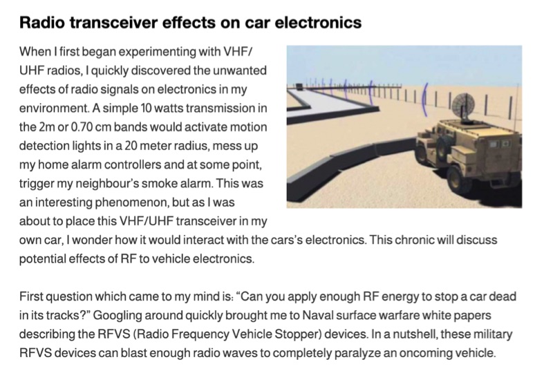 Illustrates the potential for radio frequency (RF) energy from amateur transceivers to interfere with vehicle electronics, drawing parallels to military _Radio Frequency Vehicle Stopper_ (RFVS) technology. The resource details personal experiences with VHF/UHF signals activating household devices and then pivots to the complexities of RF interaction with automotive systems, noting the development of multi-frequency RFVS (MFRFVS) to overcome vehicle-specific vulnerabilities. It highlights that while car manufacturers conduct RF immunity tests, the rigor varies, with luxury brands likely performing more extensive evaluations than others who merely meet minimal certification. The article explores practical considerations for mobile amateur radio installations, suggesting antenna placement over the car, using lower power output, and proper grounding to mitigate adverse effects. It acknowledges the lack of comprehensive data on RF/vehicle combinations but emphasizes that adherence to these basic principles can reduce risks. The author shares observations of unexplained car computer codes in a 2002 SUV, speculating on potential RF induction. Concerns are raised about the increasing complexity and interconnectedness of modern car electronics, including Bluetooth, remote access, and electronic control systems for critical functions like steering and braking. The article points out the diminishing space for third-party installations in contemporary vehicles and references the ARRL's stance on auto manufacturer policies regarding amateur radio installations, which generally advise against them.
 -
 An Arduino-based interface provides a remote tuner call command for Icom **IC7700** and **IC7800** transceivers, addressing the lack of a built-in function for external tuners such as the MFJ 998RT. This setup initiates a low-power transmit signal, typically 15 watts, allowing the remote autotuner to perform its matching sequence. The article details the required CI-V line communication and modifications to existing Arduino code, specifically referencing contributions from Jean-Jacques ON7EQ for improved Icom interrogation routines. The system involves a sequence of steps: storing the transceiver's current mode and power, disabling the internal autotuner, activating a control relay to interrupt the amplifier line, switching to RTTY mode at low power, and initiating transmit. The transmit duration is manually controlled by the operator, observing the SWR meter until a low SWR is achieved, then a second button press stops the transmission. A built-in 4-second transmit limit provides a safety measure. After tuning, the routine restores the original mode and power settings, re-enables the internal autotuner, and performs a brief 2-second RTTY transmission for internal tuner adjustment. The circuit diagram includes a Panasonic form 2 relay for amp control and emphasizes critical delays in the Arduino code for stable operation at 9600 baud CI-V communication. Compatibility with logging software like DXLab, N1MM, and N3FJP is noted, with specific interrogation time settings required to avoid conflicts.
 -
 The Gemini Amplifier Remote Control software operates on Windows 7 and above, facilitating remote management of the Gemini HF-1K and DX-1200 amplifiers. Users connect via Ethernet, configuring the amplifier's IP address through the front panel. The software allows seamless band and antenna selection, saving settings for each band without requiring transmission. Integration with _OmniRig_ from Afreet Software, Inc. enables automatic band adjustments based on the radio's frequency changes. Users can configure serial or virtual serial connections, with tracking options accessible through the ribbon bar. The software supports speech functionality, enhancing accessibility for operators. Firmware updates, such as version 2.5Ee, introduce features like background datalogging and power output control, uploaded via FTP. Version 1.2.0 allows users to offload internal parameter data for support purposes. The firmware upload process requires the amplifier's IP address and port 21, taking approximately 90 seconds. Users are encouraged to upgrade to the latest firmware for improved performance and remote diagnostics.
 -
 MeshCom 4.0 facilitates off-grid text messaging and data exchange via _LoRa_ radio modules, operating on low-power, low-cost hardware to establish networked communication capabilities. The system transmits messages, GPS positions, sensor values, and telecontrol data over significant distances with minimal power consumption. MeshCom modules can autonomously form a mesh network or integrate into a broader message network through MeshCom gateways, which ideally connect via _HAMNET_ to link disparate radio networks. Recent updates include MCMAP features, support for Lilygo T-Connect-Pro, and new firmware for T-ECHO, enhancing the system's versatility. The project provides basic specifications, detailed protocol information, and installation instructions for MeshCom 4.0, including guides for RAK WisBlock and HELTEC V3 hardware. Firmware and companion Android/iPhone applications are available for download, supporting a range of **10-20 km** line-of-sight communication.
 -
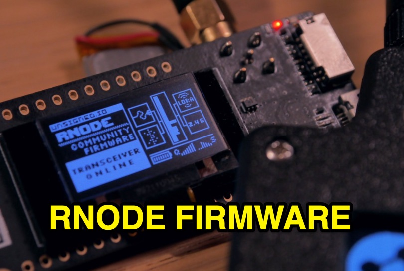 Enables digital radio transceivers to function as versatile data communication nodes, supporting applications like _Reticulum_ networking, messaging with Sideband, and acting as a LoRa-based KISS-compatible amateur radio TNC. This firmware transforms off-the-shelf development boards into powerful, long-range data radios, facilitating robust communication over significant distances, potentially achieving **hundreds of kilometers** with optimal setups. It supports a range of hardware, including unsigned.io's Handheld RNodes (v2.x and v1.x), LilyGO T-Beam v1.1, LilyGO LoRa32 (v2.0, v2.1), and Heltec LoRa32 v2 devices. Compatibility extends to transceiver modules utilizing Semtech SX1276, SX1278, SX1262, SX1268, and SX1280 chips, provided they have an SPI interface and exposed interrupt pins. Installation is streamlined via the `rnodeconf` utility, part of the `rns` package, simplifying the flashing process for users. The project operates under the GNU General Public License v3.0, promoting open development and user freedom. It encourages community involvement in building and deploying RNodes for various purposes, from personal communication to establishing resilient, decentralized networks. The firmware's design emphasizes flexibility, allowing for diverse configurations to suit specific operational requirements.
 -
 The project aims to create a remote control system for the VK5RSE beacons located near Millicent, South Australia. The beacons on 144.550, 432.550, and 1296.550 MHz can interfere with nearby amateur radio operations, particularly for EME work on 1296 MHz. The remote control system uses a DTMF decoder and PIC microcontroller to allow turning the beacons on and off individually or in combination. The system is housed in a diecast box and powered from 5-8V. The password-protected control allows authorized users to manage the beacon operations remotely, helping mitigate interference issues for local amateurs.
 -
 This resource details **cooling modifications** for Ameritron AL82, AL1200, and AL1500 HF amplifiers, specifically addressing heat issues encountered during high-duty-cycle digital mode operation. The author, WD4NGB, observed excessive heat in the tank area and band switch on an AL82, attributing it to insufficient exhaust over the 3-500 tubes and a complete lack of exhaust over the tank area. The modifications aim to prevent common failures such as damaged band switches and deformed insulating materials by increasing airflow and exhaust area. The page describes adding five holes to the chassis for enhanced cooling to the band switch and tank area, alongside enlarging the exhaust area over the inner 3-500 tube and the tank area on the amplifier cover, utilizing expanded metal for safety and RF shielding. The original cover featured 26.25 square inches of exhaust; the modified version significantly increases this to 48.5 square inches over the tubes and introduces an additional 15 square inches over the band switch. These changes are intended to resolve heating problems encountered during heavy, 100% duty cycle use in modes like RTTY or long SSB contests, which typically generate substantial heat. The article also discusses upgrading to a higher output fan, such as the G2E085-AA05-21, and modifying tube sockets for improved airflow and reduced back pressure, citing Tom Rauch (W8JI) of CTR Engineering as a source for parts.
 -
 This presentation explores the practice of QRP (low-power) amateur radio operation in outdoor settings. It guides operators to identify their specific objectives for portable operations, which inform equipment and antenna choices. The discussion covers considerations including portability, operating modes, power requirements, and weather resistance. Various antenna designs are examined, from vertical configurations to dipoles and end-fed options, with emphasis on deployment practicality in public spaces. The presentation concludes with practical advice on selecting operating locations, RF safety, and resources for equipment and community support for QRP enthusiasts.
 -
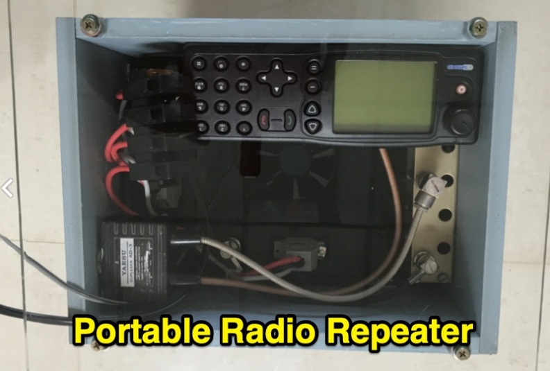 Demonstrates the construction of a portable 2-meter repeater system utilizing a **Yaesu DR-1X** transceiver, configured for both analog FM and C4FM digital voice operation. The design emphasizes portability, robustness, and effective thermal management, incorporating a "wind tunnel" airflow system with a fan to maintain transmit module temperatures at 38 degrees Celsius during continuous operation. The system integrates a diplexer, control head, and is housed in a compact, lightweight case weighing under 8kg, designed for single-person deployment. Covers practical considerations for field deployment, including power sources, antenna types, and the overall system architecture for public service events and emergency preparedness. The resource details the modular "wrap around" construction, showing how components like thermal switches for fan control and Anderson Powerpole connectors are integrated. It highlights the system's ability to provide reliable communications support for club activities and emergency communications.
 -
 The W6PQL 23cm Beacon Project describes a **1296 MHz** beacon designed for microwave propagation studies and equipment testing, capable of 30 watts output. It utilizes a PIC 16F628A microcontroller to generate CW and FSK keying for a crystal oscillator, followed by a series of frequency doublers and triplers to reach the target frequency. The final power amplification stage employs a Mitsubishi M57762 module, providing a robust 10-watt RF output. The design emphasizes stability and reliability for continuous operation, with the microcontroller code, written in assembly, provided for customization of the beacon's callsign and message. Originally located in CM97am and aimed at 140 true, the beacon used four 4-foot Yagis stacked vertically for a total ERP of 3kW. The article includes schematics, parts lists, and construction notes to guide builders, along with antenna pattern measurements. Although the beacon itself is no longer in service as of August 2010, the detailed documentation remains a valuable reference for amateur radio operators interested in building similar **microwave** projects or understanding beacon operation.
 -
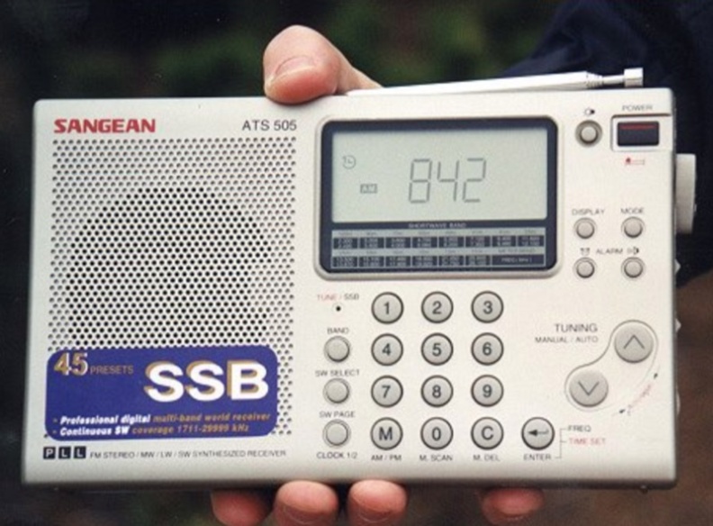 Examines the Sangean ATS-505 portable receiver, a unit introduced in March 2000, providing an in-depth analysis of its capabilities. The review details critical specifications such as its 6 Volt DC power requirement, utilizing 4 AA batteries, and its physical dimensions of 128 x 214 x 39 mm, weighing 840 g without power cells. Frequency coverage spans **LW** from 153-279 kHz, **MW** from 520-1710 kHz, **SW** from 1711-29999 kHz, and FM from 87.5-108 MHz, making it a versatile listener for various broadcast types. Key features highlighted include a backlit display for low-light operation, 45 memory presets for quick access to favorite stations, and the inclusion of Single Sideband (SSB) mode, which is crucial for serious shortwave listening and utility monitoring. The review also draws technical comparisons with other Sangean models, specifically the ATS-404 and ATS-909, pointing out differences in band coverage and operational features. This independent assessment offers practical insights into the ATS-505's performance, helping enthusiasts understand its place within the portable receiver market.
 -
 Heltec Automation specializes in the production of _ESP32-based_ LoRa development boards, wireless modules, and gateways, catering to various amateur radio applications. The product line includes devices suitable for _APRS LoRa trackers_, Meshtastic nodes, and general long-range, low-power RF projects, providing hardware solutions for digital communication experimentation. The company's offerings support diverse wireless protocols such as LoRa, LoRaWAN, Meshtastic, and Wi-Fi HaLow, enabling users to build custom communication systems. Specific products like the _Wireless Stick Lite_ and various Heltec LoRa boards are designed for integration into DIY projects, facilitating rapid prototyping and deployment of wireless solutions. Heltec provides detailed product specifications, documentation, and community support, which assists hams in leveraging their hardware for packet radio, digital modes, and IoT applications within the amateur bands. The focus remains on versatile, programmable modules that bridge traditional amateur radio interests with modern wireless technology.
 -
 Parks on the Air Canada page provides information about the popular Amateur Radio activity that involves operating portable radios from designated parks and nature reserves worldwide. The page presents the objectives of the program, lists over 400 national/provincial/territorial parks, and offers insights from Tracy McKim, VE3TWM, on low power communications and outdoor ham radio operation. It also includes links to YouTube channels with how-to videos on setting up portable stations, Field Day deployment, and POTA activation. Amateur radio operators interested in combining their love for radio with outdoor adventures will find valuable resources and learning opportunities on this page.
 -
 Presents an online retail platform for amateur radio operators, showcasing a diverse inventory of equipment and accessories. The site lists popular transceivers such as the _Icom IC-7300_ and _Icom IC-7610_, alongside various antenna solutions including base, HT, mobile, and end-fed designs. Operators can find coaxial cable, including bulk options and products from "The Wire Man," essential for shack setup. The platform also stocks crimping and stripping tools, adapters, and power supplies, crucial for station maintenance and construction. Test equipment like _RigExpert Analyzers_ and accessories such as Daiwa meters and _West Mountain Radio_ Power Poles are available. Additionally, the site offers software from _Ham Radio Deluxe_ and _RT Systems_, catering to logging and radio programming needs. Shipping policies include free shipping on C.Crane Radios and most orders over $100.00 within the lower 48 states, providing clear purchasing incentives.
 -
 Operating an **Echolink** gateway on the 4-meter band presents unique opportunities for extending VHF communications, as demonstrated by the EI4FMG node. Situated at Fieldstown, Monasterboice, this gateway provides coverage across a significant portion of Ireland's east coast, leveraging a Tait TM8100 radio and an EI4JR Echolink interface logic. My own experience with similar setups confirms the importance of strategic site selection for maximizing reach, particularly with a 122-meter elevation above sea level. Access to the EI4FMG gateway, identified by node 57006, requires a **CTCSS** tone of 88.5 Hz, a standard practice for managing access and minimizing interference on shared frequencies. The system transmits with 15 watts of power and utilizes a Sigma CAT70 @5MAGL antenna, a configuration well-suited for regional VHF coverage. The gateway also features an auto-ID every 8 minutes, ensuring compliance and clear station identification. Users can interact with the gateway using various DTMF commands, allowing for connections to specific nodes, random repeater/link or conference nodes, and managing disconnections. These functionalities streamline the process of linking into the broader Echolink network, enabling local VHF operators to communicate globally through the internet backbone.
 -
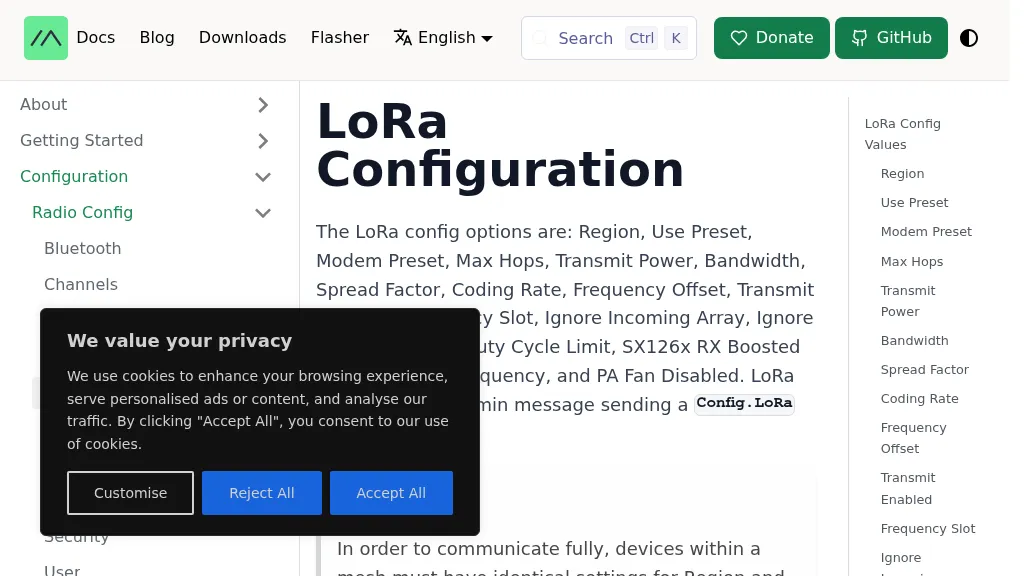 The Meshtastic documentation outlines critical LoRa configuration parameters for node operation, emphasizing regulatory compliance. It details settings such as Region, Modem Preset, Max Hops, Transmit Power, Bandwidth, Spread Factor, Coding Rate, and Frequency Offset. A comprehensive table provides region codes, frequency ranges (e.g., US **902.0 - 928.0 MHz**), duty cycles, and power limits (e.g., EU_433 **12 dBm**) for numerous countries, including the US, EU, China, and Japan, alongside a 2.4 GHz band option. It explicitly states that devices within a mesh must share identical _Region_ and _Modem Preset_ settings for full communication. Modem Presets, like _LONG_FAST_ (the default), optimize for either speed or range, directly impacting network congestion and message delivery delay. For instance, SHORT_TURBO offers the fastest speed and shortest range, while VERY_LONG_SLOW provides the longest range but is less reliable for mesh formation. The document also highlights specific duty cycle limitations, such as the 10% hourly limit for EU_433 and EU_868 regions, and provides command-line interface (CLI) examples for configuring these parameters.
 -
 This online construction guide details the assembly of a signal generator specifically for the **13cm band** (2.4 GHz). The curriculum focuses on the integration of a Voltage Controlled Oscillator (VCO), specifically the ROS-2400, to produce a stable RF signal. The resource outlines the necessary components for frequency generation and output, including the use of a Mini-Circuits MMIC amplifier for signal conditioning. The construction protocol involves configuring the ROS-2400 VCO to operate within the 2.3 GHz to 2.45 GHz range, ensuring frequency coverage for amateur radio _microwave experimentation_. The guide specifies the output power level, approximately 70mW, directly from the MMIC stage, indicating its application as a low-power instrumentation source rather than a transmit-capable device. This project provides a practical example of constructing a dedicated test instrument for microwave frequency measurements and system alignment on the **13cm band**. DXZone Focus: Construction Guide | 13cm Signal Generator | VCO Integration | Microwave Experimentation
 -
 Demonstrates firmware for microcontrollers like the _ESP32_ to implement a LoRa APRS iGate and Digipeater. This project leverages LoRa for packet radio communication, allowing amateur radio operators to bridge the gap between LoRa-enabled APRS stations and the global APRS-IS network via WiFi. It details the setup for both iGate and Digipeater modes, including features like transmitting APRS-IS packets over LoRa to local stations and a 30-second buffer in digipeater mode to prevent packet storms. This firmware offers an Ultra Eco Mode, achieving current consumption between **7mA** and **13mA**, making it suitable for remote, battery-powered deployments. The integrated WebUI simplifies configuration and management, providing an accessible interface for hams to deploy and maintain their LoRa APRS infrastructure. It supports sending weather telemetry packets and adheres to APRS protocols, released under the GPL-3.0 license.