Search results
Query: circuit
Links: 360 | Categories: 14
Categories
- Software > Circuit Design
- Technical Reference > Batteries
- Technical Reference > Batteries > Battery Charger
- Technical Reference > Electronics
- Manufacturers > Test Equipment > Impedance Analyzers
- Technical Reference > Morse Code Oscillator
- Technical Reference > Test Equipment > Multimeter
- Software > PCB Design
- Technical Reference > Receiver Front-End Protector
- Software > RF Design
- Technical Reference > Soldering and Desoldering
- Technical Reference > Transverters
- Technical Reference > Vacuum tube
- Software > Vector Network Analyzer
-
 The Pressure Paddle V2.0 simplifies the original 2019 design by using MOSFETs’ unique properties for reliable, minimalistic switching. When pressure sensors detect a press, they reduce resistance, activating the MOSFET and lowering voltage until it stabilizes at the MOSFET’s threshold. This ensures consistent “key down†signals for the transceiver. Compatible with 3-5V logic systems, the circuit operates independently of pull-up resistor size. The PCB is lightweight, easy to assemble, and can be packaged in heat shrink or mounted. This version maintains durability with fewer components and flexible packaging options.
 -
 The Yaesu VX-6R USB Programming Interface is a reliable solution for programming the Yaesu VX-6R handheld radio using USB. Based on the FT232RL chip, it replaces older RS232 interfaces and USB converters, ensuring stable communication. The design integrates a buffering circuit with a Sparkfun breakout board, featuring TX and RX LEDs for easy monitoring. The compact interface connects to the radio via a four-pin header, with a solder bridge option for radios requiring separate data lines. This setup has proven reliable and versatile, allowing the FT232RL to be repurposed for other projects.
 -
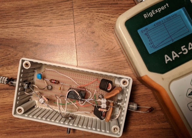 The article describes adding lightning protection to Beverage antennas, which are long wires susceptible to lightning strikes. The author reviews common lightning protection circuits and discusses their components. They then detail their design based on existing methods, highlighting choices for components and reasoning behind them. Finally, the author presents the completed design and its implementation on their Beverage antennas.
 -
 The article details how to eliminate Radio Frequency Interference (RFI) from the Behringer HA400 headphone amplifier when used in ham radio setups. While the HA400 is praised for its quality and affordability, it was not designed for RF environments, causing distortion when used with a 500-watt radio station. Initial attempts using clamp-on ferrites on the headphone and power cables only partially resolved the issue. Upon opening the unit, the author discovered the circuit lacked RF bypassing components. The solution involved installing 0.1μF (104) capacitors at key points in the circuit: the power supply input, audio circuits, and op amp inputs. This modification, combined with the external ferrites, completely eliminated the RFI problem, making the unit suitable for ham radio operations.
 -
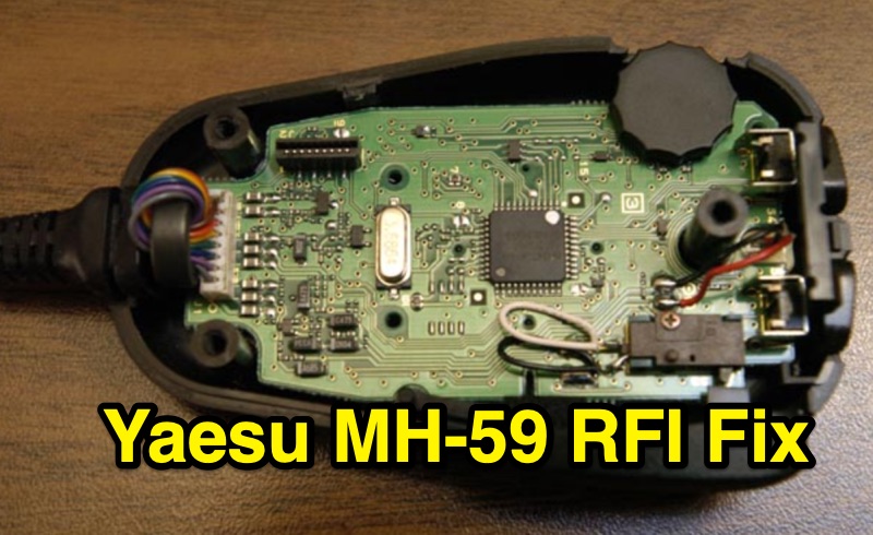 This resource details a practical RFI fix for the Yaesu MH-59 microphone, specifically addressing interference encountered during Field Day 2004 operations. The modification involves installing a small toroid core onto the microphone's internal cable connector. The author, AE7Q, describes the process: purchasing a ½" outer diameter, ¼" inner diameter toroid core from a surplus store, opening the MH-59, unplugging the cable connector from the circuit board, looping the cable through the toroid, and then reassembling the microphone. This fix is intended for amateur radio operators experiencing RFI with their Yaesu MH-59 microphone, particularly in environments with strong RF fields like those found at Field Day events. The page also directs users to the AE7Q message board for questions and comments.
 -
 VE2AZX's 2013 Radio Talk presentation details the technical aspects of baluns, including reasons for their use, various types, and methods for performance verification using an SWR analyzer. The document specifically examines 1:1 voltage baluns and 4:1 voltage baluns, outlining their winding configurations and typical impedance transformations. It presents empirical SWR measurements for W2AU 1:1 baluns and Unadilla 4:1 baluns, tested with both 50-ohm and 200-ohm resistive loads across the HF spectrum. The presentation further explores the measurement of ferrite impedance and their application in mitigating common-mode currents on feeders and household conductors. Key concepts addressed include balanced-to-unbalanced transformation, ensuring feeder independence from the antenna, and reducing unwanted feeder radiation. The content emphasizes practical testing procedures to ensure optimal antenna system performance and minimize RF interference. Discussions also cover open-circuit tests with SWR analyzers and VNAs to assess winding inductance, distributed capacitance, and insulation quality. The presentation differentiates between voltage and current baluns, explaining how current baluns, particularly those utilizing ferrite cores, reduce outer shield currents without affecting internal coaxial cable currents, thereby preserving the antenna's intended radiation pattern.
 -
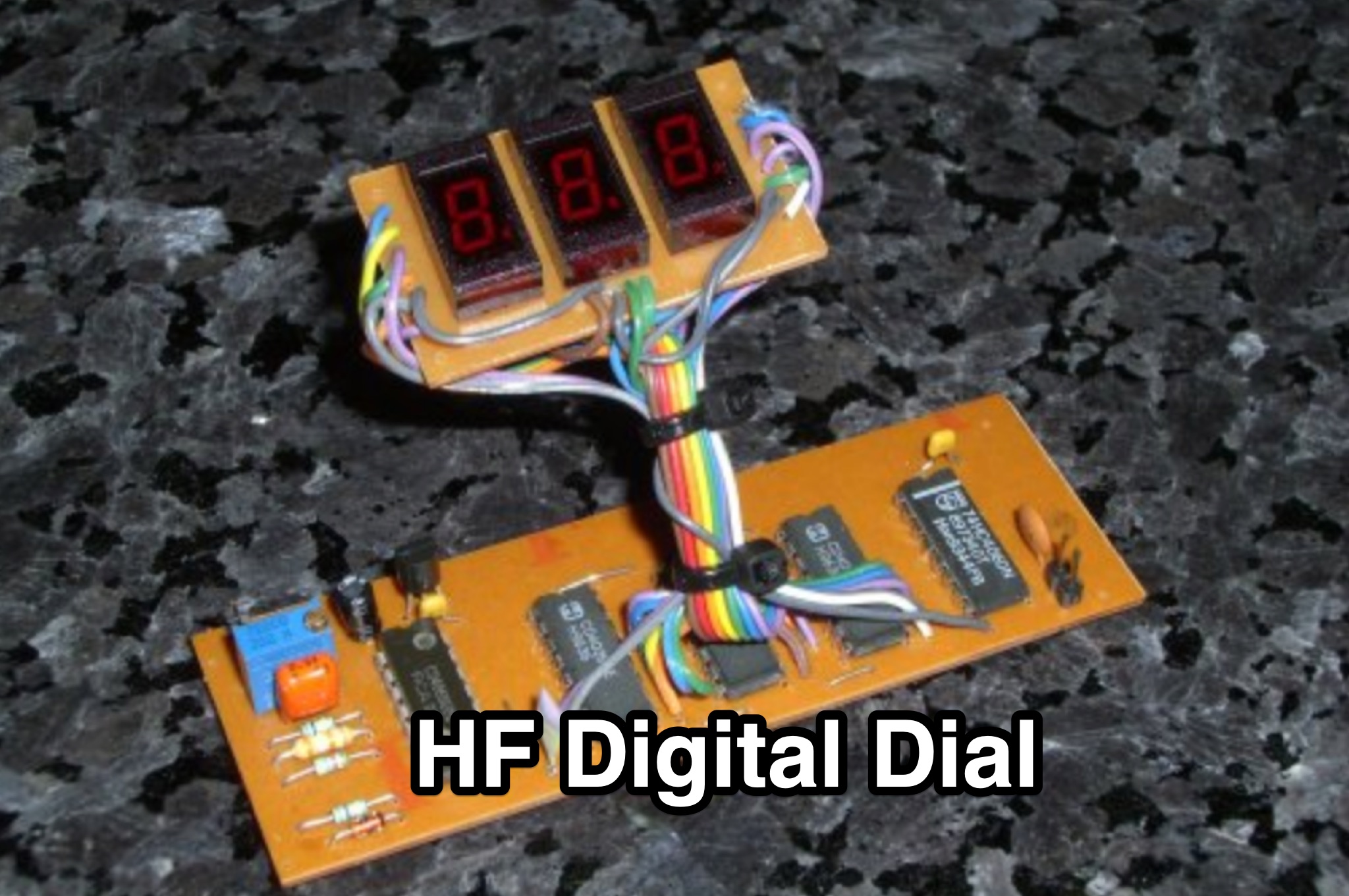 This page by Andrew Woodfield ZL2PD provides information on CMOS HF Digital Dial for hams. It covers design options, circuit description, construction, alignment, and operation. The page also includes references and downloads. Whether you're looking to build or understand a digital dial for your HF rig, this page offers valuable insights and resources.
 -
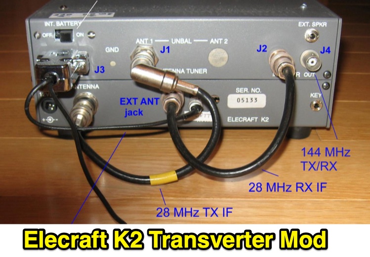 Demonstrates the conversion of an _Elecraft K2_ QRP HF transceiver to serve as a 2-meter Intermediate Frequency (IF) rig for microwave transverters, addressing the obsolescence of older _Yaesu FT-290R_ units. The project integrates a _DEMI 144-28DC_ transverter board, configured for a 28 MHz IF, and details the necessary modifications to the K2, including the installation of the K160M module for a separate receive-only antenna input and the KSB2 SSB module for voice operation. The modified K2 provides a stable 1-watt output for the 2m IF, utilizing the QRP antenna jack for transmit and the K160M input for receive, with a custom PTT control circuit. The article outlines the physical integration and electrical interfacing, including the design of an internal attenuator for the 28 MHz IF output and a control circuit for the 144 MHz interface. It also covers the construction of a medium power amplifier using an _MGA-31389 MMIC_ to boost the 2m output to 100 mW, matching the original FT-290R performance. Performance measurements for the amplifier, including output power versus input power and gain versus frequency, are presented. The project culminates in a fully integrated solution, with schematics and photos illustrating the internal wiring and external connectors. The modified K2, dubbed the "K290R," was successfully deployed in the 2017 _ARRL 10 GHz and Up Contest_ with a _Kuhne 10 GHz_ transverter, demonstrating reliable operation for CW and SSB modes.
 -
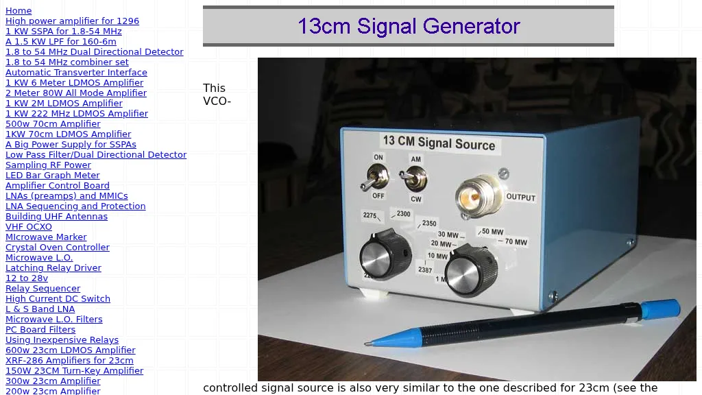 This online construction guide details the assembly of a signal generator specifically for the **13cm band** (2.4 GHz). The curriculum focuses on the integration of a Voltage Controlled Oscillator (VCO), specifically the ROS-2400, to produce a stable RF signal. The resource outlines the necessary components for frequency generation and output, including the use of a Mini-Circuits MMIC amplifier for signal conditioning. The construction protocol involves configuring the ROS-2400 VCO to operate within the 2.3 GHz to 2.45 GHz range, ensuring frequency coverage for amateur radio _microwave experimentation_. The guide specifies the output power level, approximately 70mW, directly from the MMIC stage, indicating its application as a low-power instrumentation source rather than a transmit-capable device. This project provides a practical example of constructing a dedicated test instrument for microwave frequency measurements and system alignment on the **13cm band**. DXZone Focus: Construction Guide | 13cm Signal Generator | VCO Integration | Microwave Experimentation
 -
 W4EEY offers specialized preparation materials focused on the mathematics and electronics theory portions of ham exams. Their approach breaks down complex formulas into step-by-step processes, making them accessible even to those without strong math backgrounds. The site includes calculators for common ham radio formulas, interactive circuit diagrams, and in-depth explanations of electronic principles. Their materials are particularly valuable for the Amateur Extra exam, where technical content becomes more challenging.