Search results
Query: 20m vertical
Links: 36 | Categories: 1
Categories
-
 This antenna is fed for vertical polarisation, to give a low angle of radiation for DX and also a nearly omni-directional radiation pattern.
 -
 An effective 10-20m DX antenna for deed restricted lots. The article by K7ZB introduces a simple 10-20m DX antenna suitable for deed-restricted lots. The antenna, a 15' vertical design, facilitated contacts with over 200 countries worldwide. Its design employs a telescopic aluminum tube and radial wires for multi-band operation, requiring an external antenna tuner for optimal performance. The mounting scheme and construction details ensure effectiveness and ease of use.
 -
 A self-supporting vertical antenna design for stationary-mobile HF-VHF operation is presented, emphasizing ease of construction with common materials like a fiberglass fishing rod and PVC pipe. The design focuses on creating a set of no-tuner monoband radiators for bands such as **2m**, **6m**, 10m, and 12m, with an overall radiator support length of 3.3m. The construction process details the assembly of the antenna base using a magnetic mount, PL-259 connector, and PVC pipe sections, which then supports the telescopic fishing rod. Radiator extensions are cut to achieve quarter-wave resonance on specific bands, with detailed instructions for 6m (50-51 MHz), 10m (28.5 MHz), and 12m (24.9 MHz). For lower HF bands like 15m, 17m, and 20m, the design incorporates base-loading coils, with specific turn counts provided (e.g., 21 turns for 20m). The project also suggests using an _antenna analyzer_ for precise tuning of extensions and coils, moving beyond theoretical values to achieve optimal performance. The author, _IK1ZYW_, notes that for 80m and 160m, the antenna becomes less efficient as a vertical, suggesting alternative configurations like an inverted-V dipole or asymmetrical inverted-L.
 -
 20m T-Monopole short vertical antenna for 20 meters by AA5TB
 -
 This multiband wire antenna it is an off centre fed dipole, with 10 feet of vertical radiator, needs no tuner on 40m, 20m and 10m and works fine on all bands above 40m with a tuner, and even below 40m on 60m, and 80m.
 -
 20 meter wire j-pole for 14.2 MHz, a vertical, end-fed half wave antenna by N1LO
 -
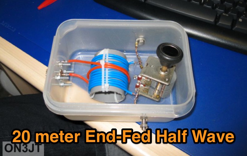
 Constructing an HF End-Fed Half-Wave (EFHW) vertical antenna, the resource details the winding of a monoband matching unit, inspired by _AA5TB_, designed to provide a 50 Ohm impedance match without a ground plane or antenna tuner. It specifies the use of a _T200-2_ ferrite core for the transformer, outlining the 13-turn secondary and 2-turn primary winding process with enamelled copper wire. The document also describes the integration of a coax capacitor, whose length is critical for tuning and varies by band, with specific starting lengths provided for 20m, 17m, 15m, 12m, and 10m operation. The practical application section guides the builder through tuning the antenna using an antenna analyzer, emphasizing the iterative process of spacing secondary windings and trimming the coax capacitor to achieve resonance at the desired band frequency. It highlights the antenna's low angle of radiation, beneficial for DX, and claims up to 2 S-points improvement over a _G5RV_ or similar doublet when used as an omnidirectional vertical. A comprehensive shopping list, including specific part numbers from _Rapid Electronics_, is provided, along with advice on selecting fiberglass fishing poles for support and suitable antenna wire.
 -
 A simple and low cost multiband vertical hf antenna covering 5 bands (20m-10m) from an old CB antenna
 -
 5 Band 1/4 wave Telescopic Antenna. The 20m to 10m, antenna is simple and cheap to make, and has a performance that matches commercial antennas but at cost considerably lower. The design was purposely based on a telescoping fibre glass fishing rod as this allows it to be easily stowed away in the car.
 -
-
 The document details the optimization and construction of the _Maria Maluca_ antenna, a compact 6-band (20m-6m) directional beam. It presents a comparative analysis of shortwave antenna principles, highlighting the efficiency gains achieved by using an open feeder line and tuner as a resonant unit, contrasting this with the losses associated with traps or capacitive loads in multiband antennas. The resource specifically revisits an older South American 2-element design for 10, 15, and 20 meters, applying modern NEC-based software to develop a six-band version. Performance data is meticulously tabulated, showing impedance, free space gain, gain at 12m height, elevation angle, and front-to-back (F/B) ratio for each band from 20m through 6m. For instance, on 15m, the antenna achieves 5.1 dBd free space gain and 13.72 dB F/B ratio. The construction section provides practical guidance on element assembly using aluminum pipes and hose clamps, detailing the use of a heavy-duty glass fiber reinforced polyamide rod for electrical separation and bending strength. It also specifies the use of 450-ohm _Wireman_ line CQ 552 for the transmission line. The document includes diagrams for rod fixing, an air-wound balun, and a vertical elevation diagram for the 15m band, illustrating its DX qualification. It also discusses the antenna's suitability for portable and expedition operations, noting its compact transport dimensions (max 1.50m length, 12 lb weight) and quick assembly time (under 15 minutes). The author, Dipl.Ing. Helmut Oeller, DC6NY, is identified as a source for material kits.
 -
 An homemade portable vertical antenna with a trap near the mid point of the main element. The trap is made with 42mm diameter PVC pipe with 9 turns of wire on it
 -
 Demonstrates the product line of _LZ Antenna Ltd._, a Bulgarian manufacturer specializing in amateur radio antennas and custom electronic devices. The company focuses on robust, high-quality HF multiband Yagi and vertical antennas, leveraging over 20 years of experience from founder Georgi Georgiev in radio amateur development. Featured models include the LZA 8-4, LZA-10-3, and the LZA-7-3A WRTC 2022, alongside various rotary dipoles like the LZA1 40/30m. Provides specifications for several Yagi antennas, such as the LZA-9-5, LZA-13-7, and LZA-6-3 (a 6-element, 3-band design). The company emphasizes applying "leading edge technology" to high-frequency communication equipment production, with products designed for durability and performance. The LZA-10-5 Yagi offers **12.5 dBi** gain on 10m, while the LZA-13-7 provides **13.2 dBi** on 20m, showcasing competitive gain figures for DXing and contesting.
 -
 A Half wave antenna has a high impedance feed point. This can be matched using a 1/4 wave stub matching section and converts the 40m vertical into an L-shaped 20m J-Pole antenna. The 300 ohm feeder used for this purpose must be kept away from the ground.
 -
 GW4ALG's _136 kHz Pages_ document the evolution of vertical antennas for the 2200m band, starting with a prototype mounted on a house wall. This initial design, despite achieving the first **395 km** GM-GW QSO, suffered from significant insulation breakdown, high RF losses due to proximity to the house, and difficult tuning adjustments. The author details the challenges of maintaining resonance and matching with a variometer in the loft, noting that adding three earth spikes offered no measurable improvement over a simple water tap connection. The subsequent experimental 12m vertical, relocated away from the house, significantly reduced dielectric losses and proved far more effective. This antenna enabled GW4ALG to set a world DX record on 136 kHz with a **1916 km** QSO to OH1TN, and an intra-UK record of **703 km** to GM3YXM/P. The resource further explores the use of helium-filled balloons to extend the vertical radiator, achieving heights up to 27m, typically 20m, for enhanced low-band performance. Practical advice on balloon types, inflation, and critical insulation between the wire and balloon is provided, emphasizing safety and avoiding arcing.
 -
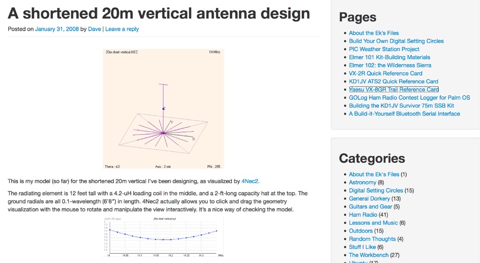 A shortened 20m vertical antenna design made with 4Nec2
 -
 An off centre fed dipole, with 10 feet of vertical radiator. It needs no tuner on 40m, 20m and 10m by M0UKD
 -
 Demonstrates the construction and implementation of a **two-element phased vertical array** for 40 meters, utilizing _Christman phasing_ techniques. The author, W4NFR, details the process from building individual 1/4-wave aluminum verticals to integrating them into a phased system. The resource covers antenna spacing of 32 feet, elevated radial design, and the critical steps for tuning each vertical to achieve a 1.1:1 SWR before combining them. It also provides insights into calculating precise coax lengths for feedlines and the phasing delay line, emphasizing the use of an MFJ-269 Antenna Analyzer for verification. The finished system exhibits good front-to-back nulls, with an overall SWR ranging from 1.6:1 to 2.2:1, which is managed by an antenna tuner. The project includes detailed photos of the relay box, showing 12 VDC relays capable of handling 5KV, and the control box in the shack for switching between three different antenna pattern configurations. Static bleed-off chokes are incorporated for protection, and the construction emphasizes robust weatherproofing for outdoor elements.
 -
 Which is better a 20m antenna for an island DXpedition: Yagi at 25', or a vertical or two on the beach?
 -
 Documents the OC1I and OC6I IOTA DXpeditions to Peru, specifically highlighting operations from SA-098 (Isla La Leona) and SA-076 (Isla Lobos de Afuera). The OC1I team logged over **8000 QSOs** from SA-076, while OC6I made 1400 QSOs from SA-098, despite challenging propagation conditions. The resource details the equipment used, including an _IC-7000_, an IC-706mkIIG, and a TS-440SAT, along with various antennas such as a 160m dipole, FD4, G5RV, and a multi-band vertical for 17m, 20m, 30m, and 40m. The DXpedition dates are specified: OC6I operated from SA-098 between December 28 and December 30, while OC1I was active from SA-076 from January 2 to January 7. Both operations are confirmed as valid for IOTA credit. The page also includes a video link for the OC6I operation and a photo gallery from the DXpedition. Feedback is welcomed, and the webmaster is identified as Bodo Fritsche, DL3OCH.
 -
 Top Loaded Vertical Antenna 3,5 MHz 80m and a 14 MHz Trap for the 20m band. The weight of this portable vertical antenna is less than 1 kg, including the ground network. The weight of the telescopic fiberglass fishing rod is another 1kg. The rod expands from 1.5 meters to 8 meters.
 -
 The PAC-12 Antenna, a multi-band portable vertical, is meticulously detailed in this construction article by James Bennett, _KA5DVS_. The design emphasizes ease of homebrewing using readily available components from local hardware stores, including replaceable loading coils. It outlines the preparation of the 72-inch telescoping whip (originally from Radio Shack, with an alternate source now provided by _Pacific Antenna_), the construction of the loading coils from PVC risers, and the fabrication of the aluminum rod base sections. Specific instructions cover threading aluminum rod with a _1/4-20 threading die_ and assembling the feedpoint insulator with a BNC connector, along with recommendations for radial deployment. KA5DVS, an avid traveler and QRP enthusiast, developed the PAC-12 to address the bulkiness of random wire setups and the limitations of commercial portable antennas like the Outbacker or SuperAntennas MP1. His goal was a lightweight, packable antenna that disassembles into 12-inch sections, achieving an assembled length of approximately 8 feet. The design strategically places the loading coil away from the base for improved efficiency. The PAC-12 notably placed first in efficiency compared to a quarter-wavelength wire vertical at the HFPack antenna shootout during the Pacificon conference in October 2001, demonstrating its practical performance for field operations. Appendix C showcases various _NJQRP Club_ members' PAC-12 constructions, including a 20m beam made with multiple PAC-12 elements.
 -
 Operating as FY/F5UII, Christian F5UII conducted a DXpedition to French Guiana (FY) from January 13 to 30, 2013. The primary operation utilized the FY5KE radio club station in Kourou, with activity focused on voice modes during specific weekday hours. The resource details the operator's intent to transmit before 12:00z and after 22:00z, or as availability permitted, from the mainland. A significant aspect of this operation involved a dedicated weekend activation of the Salut Islands, specifically **IOTA SA-020**, from January 19-20, 2013. This segment of the DXpedition was conducted from Royal Island (Ile Royale), part of a group including Devil's Island (Ile du Diable) and St. Joseph Island (Ile Saint Joseph), located 14 km offshore from Kourou. The station setup for the IOTA activation included 100 Watts of power, a GPA-030 vertical antenna for 10m, 15m, and 20m, and dipole antennas for 17m and 40m, with antenna deployment contingent on site conditions and propagation. The operator anticipated strong interest for the SA-020 entity.
 -
 This article documents the author's journey in building, modifying, and testing a DIY short vertical antenna for 40, 30, and 20 meters, with potential 80m capability. Initially inspired by Parks On The Air (POTA), the author explores pedestrian mobile operation and details various experiments to enhance antenna performance. The piece highlights challenges, SWR tuning, portability, and practical results, emphasizing a balance between efficiency and size. Ultimately, it showcases the adaptability of DIY antennas for portable ham radio applications.
 -
 Constructed in May 2008, this innovative 4m tall electrically full-size halfwave vertical dipole, tunable to multiple bands, offers HF coverage despite its space-saving design. Inspired by cost-effective DIY alternatives, the antenna design departs from conventional center-fed approaches, utilizing asymmetrical dimensions. Despite resonance challenges, the antenna's performance remains viable, boasting broad bandwidth and adaptability, as demonstrated through SWR measurements and EZNEC predictions.
 -
 a 20M quarter-wave vertical antenna with a 6m telescopic mast, 1:1 balun, and spiral-wound driven element. Designed for QRP at 14.285 MHz, the antenna’s performance exceeded expectations, delivering low SWR and surprisingly quiet reception. Initial testing yielded successful contacts with European stations and EC1KR, showcasing its effectiveness. Compact and easy to deploy, the antenna promises to be an excellent portable solution for future hilltop operations.
 -
 A coaxial cable trap is a fundamental component in multiband antenna design, enabling a single radiator to resonate efficiently on multiple frequencies by electrically shortening or lengthening the antenna element. This project focuses on constructing such a trap for a vertical antenna operating on the 10 MHz (30m) and 14 MHz (20m) amateur bands, providing practical insights into its fabrication and integration. The article outlines the specific dimensions and winding techniques for the coaxial trap, emphasizing the use of readily available materials. It details the physical construction of the vertical element, including the mast and radiating sections, to achieve optimal performance across both target bands. The author shares personal experiences with similar trap designs, noting their effectiveness in previous horizontal dipole configurations. Key construction steps are illustrated with _original photos_, showing the assembly of the trap and its incorporation into the overall antenna structure. The design aims for a compact footprint, making it suitable for limited space installations while still delivering effective DX capabilities on the **30-meter** and **20-meter** bands.
 -
 This blog chronicles the development of an 80-meter vertical antenna for amateur radio operation. The author constructs a top-loaded vertical using fiberglass poles, achieving significant performance improvements over their previous end-fed wire antenna. Comparative testing using the Reverse Beacon Network and on-air contacts demonstrates 8-10 dB gain on the east coast. The project evolved to include 40-meter capability through a modified design featuring a four-wire vertical cage, loading coil, and strategic guying system. Despite challenges with signal wobble during windy conditions, the vertical consistently outperforms the end-fed wire, particularly for reaching distant stations during nighttime propagation.
 -
 The reason for making this antenna was the desire for a vertical (hence DX-ish) antenna that would cover at least 20m that would fit on my 5m fishing pole. This antenna can work on 20m 17m 15m bands and it is suitable for SOTA operations
 -
 WB8LZR details the construction and initial field results of a multi-band vertical wire antenna, designed to complement his existing horizontal loop for improved DX on 80 meters. The antenna utilizes a 67-foot vertical wire, configured as a quarter-wave radiator on 80m, and employs a 1:1 current balun for RF isolation on 80m, 30m, and 17m. For bands like 40m, 20m, and 10m, where the wire acts as a half-wave or full-wave radiator, an additional impedance transforming _unun_ is integrated to manage the significantly higher feedpoint impedance and voltage. The author notes the vertical's performance as a receiving antenna, observing reduced noise compared to his main horizontal loop, particularly on 80m, and even hearing some long-path signals the loop missed. Initial QRP contacts, including a **1-watt** QSO with a _VP2 station_ on 30m, demonstrate its transmit capability. While the radial system is currently rudimentary, the project outlines practical considerations for multi-band vertical deployment and impedance matching.
 -
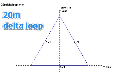
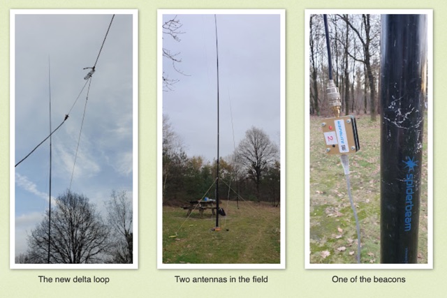 Intrigued by a German OM positive experience with a 20m delta loop, the author replicated the design, noting its favorable 50-ohm impedance compared to their 40m version. Testing against a vertical EFHW, the delta loop excelled within EU but lagged at longer distances. Despite needing more testing, the user leaned towards the EFHW for its overall performance and practicality.
 -
 This study details a reception comparison between vertical and horizontal active loop antennas, specifically two identical _Wellgood active loop antennas_, on various HF bands. The experiment, conducted in a densely populated QRM-prone area, monitored FT8 signals over a 24-hour period using two identical receivers. The methodology involved direct comparison of signal reception across the HF spectrum, aiming to identify performance differences based on antenna orientation. The results indicate that vertical loops demonstrated superior performance on higher bands (10m, 15m, 20m), while horizontal loops excelled on lower bands (30m, 40m, 160m), particularly for receiving long-distance (DX) signals. The horizontal loop's advantage on lower bands is attributed to potentially better low-angle performance and reduced sensitivity to man-made noise, yielding a **2-3 S-unit** improvement on 160m. The study provides practical insights for optimizing antenna placement in challenging urban environments, noting that the horizontal loop consistently showed a **10-15 dB** signal-to-noise ratio improvement on lower bands.
 -
 The Butternut HF2V, originally a two-band vertical antenna for 80m and 40m, was enhanced by the user to include 30m and 20m bands for better digimode DX work during the solar minimum. The additions used components adapted from the HF6V and innovative methods for the 20m addition, either through a parallel vertical element or a lower-mounted independent element, minimizing band interaction. This modified four-band antenna now supports high power across popular HF bands using a single feedpoint.
 -
 PH0NO conducted field tests comparing a mobile antenna (DX-UHV) to an end-fed half-wave wire. Results on 20m showed the end-fed wire outperforming the mobile antenna, with a significant difference in signal strength. On 40m, the end-fed wire surpassed the mobile antenna in spots and reach. While the mobile antenna is more practical, the end-fed wire offers superior performance. Further testing is planned.
 -
 The 1/4 wavelength vertical antenna project, initially designed for 20 meters, has evolved into a versatile portable solution covering 10 through 60 meters. K0BXB details its construction, emphasizing a bottom-loaded design with a tapped loading coil and four 10-foot counterpoise wires. The author shares personal experiences and field results, including **18 QSOs** during a park activation on 17m and 30m with 10 watts, and a **2,435-mile** contact with a contest station in Bonaire on 20m using 5 watts. Comparisons are drawn to commercial offerings like the _Wolf River Coils TIA_ and _QRPGuys Triband Vertical_, highlighting the DIY antenna's small footprint, light weight, and ease of tuning for POTA activations. The resource includes insights into using test equipment such as the _NanoVNA_ for SWR optimization and discusses various radiator lengths, from 17-foot wire to a 102-inch whip, demonstrating adaptability for different portable setups. Construction tips cover coil winding, tap placement, and connecting feedlines and radials using common components.
 -
 This article presents a novel Top Loaded End-Fed Half-Wave (TLEFHW) antenna design for 20-meter ham radio operation. The antenna features a compact 14-foot vertical radiator with a capacitance hat configuration, eliminating the need for radials or ground systems. Using EZNEC modeling and field testing, the design achieves a 1.5:1 SWR across the 20m band with a 4.11 dBi gain. Key features include quick deployment, lightweight construction, and directional radiation pattern with 110-degree beamwidth. The design, while requiring a 45-foot footprint due to the top hat, offers an effective portable solution for amateur radio operators seeking a no-ground, no-tuner 20m antenna option.