Search results
Query: 70 cm
Links: 163 | Categories: 2
-
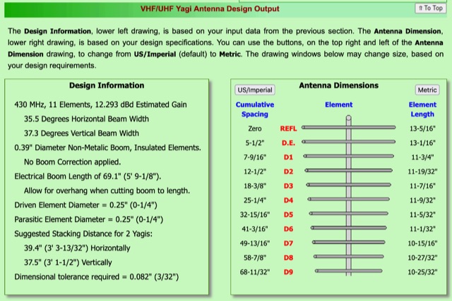 Design your VHF UHF Yagi antenna online, a JavaScript enhanced web page that implements the design of an antenna for 2m and 70cm bands. This page offers a streamlined experience for Yagi antenna design enthusiasts. It assumes prior knowledge of Yagi design principles, minimizing distractions with a user-friendly interface. Equipped with essential equations, it provides instant design feedback. Red font warnings indicate design limitations, ensuring practical results. Constraints include Gain (11.8-21.6 dBd) and Boom Length (2.2-39 wavelengths), with additional frequency-dependent restrictions noted in input fields.
 -
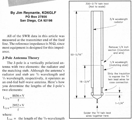 An Easy Dual-Band VHF/UHF vertical Antenna made with a TV twin lead and coax cable
 -

-
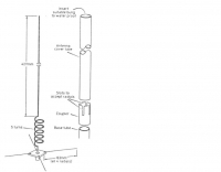
 A 9 dB gain 70cm collinear antenna construction is detailed, utilizing eight half-wavelength sections of _RG58/U_ coaxial cable. The design incorporates specific calculations for velocity factor (0.66 for RG58/U) to determine precise element lengths, such as 223mm for a half-wavelength at 444 MHz. A quarter-wave radiating element of #16 solid wire, 169mm long, is added to the top, and a 160mm aluminum tube acts as a quarter-wave counterpoise at the feed point. RF choke baluns, constructed from three _FT50-43_ toroids, are positioned a half-wavelength from the feed point to mitigate common mode current. Assembly involves soldering the coax sections in series, followed by SWR testing during construction and final mounting within a ¾-inch PVC pipe. The article suggests using four half-wave elements for a shorter antenna, noting a potential slight increase in SWR, which can be mitigated with quarter-wave ground radials. The design principles and formulas are scalable for other VHF/UHF bands like 6m, 2m, or 1¼m, providing a versatile homebrew solution for enhanced gain.
 -
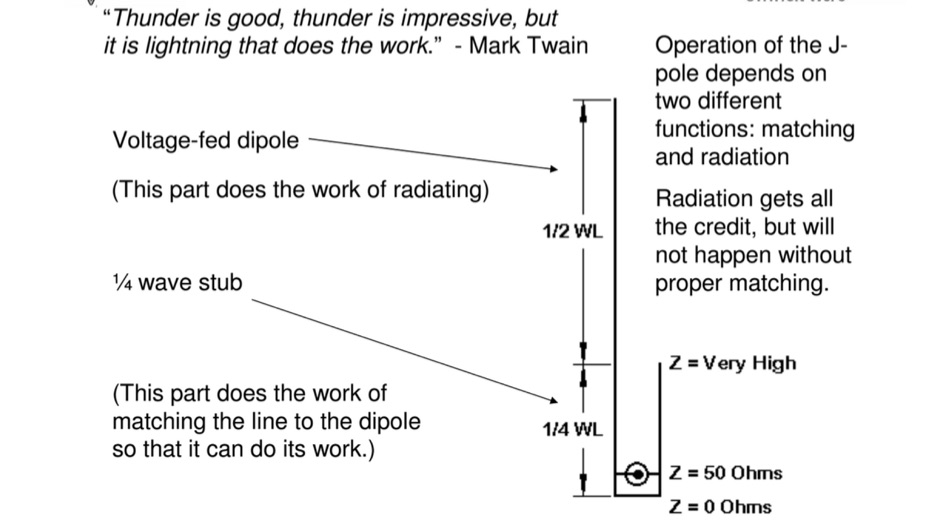 How to Build a Dual-Band Antenna for 2M/70cm presentation PDF file
 -
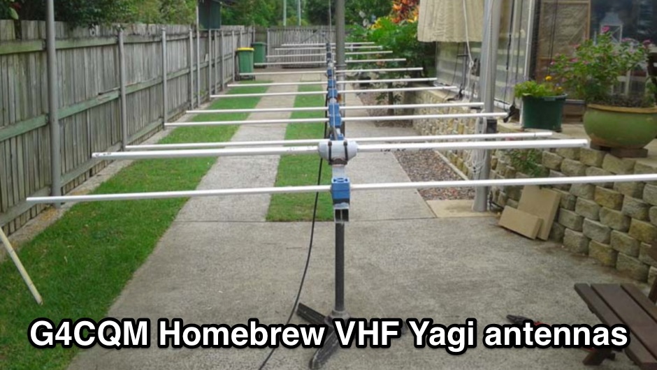 Homebrew VHF Yagi 50MHz 144MHz 432MHz 1296MHz 2320MHz 6M 2M 70CM 23CM 13CM Yagis
 -
 Here is a 70cm (440 Mhz) J-Pole antenna that is inexpensive, and easy to build. Author use 1/2 inch copper pipe, and the associated fittings necessary. The dimensions aren't typical however, this is what it took to get its SWR low.
 -
 Over 25,000 amplifiers and sub-assemblies were produced by Angle Linear for the communications industry over a 40-year period. The company specialized in **high-linearity RF products**, focusing on preamplifiers, bandpass filters, and receiver multicouplers. Specific product lines included PHEMT and GaAs FET preamplifiers, offering both quadrature and single-ended configurations for various signal levels. The offerings encompassed coaxial and combline bandpass filters, along with integrated filter-preamplifier assemblies. The company also provided custom RF assemblies, addressing applications such as MRI preamplifiers, passive radar, and EME (moon bounce). Their product range covered VHF and UHF frequencies, including specific designs for 2m, 70cm, and 23cm bands, often featuring high IP3 performance. Technical documentation, such as filtering application notes and duplexer theory, was also associated with their product offerings.
 -
 Yagis for homemade with a new match-system, for 6m, 4m, 2m, 70cm and Shortwave
 -
 Here is a very simple 70cms dipole from Harald PD2HFE, which uses a single piece of RG-213 coaxial cable 34 cms in length.
 -
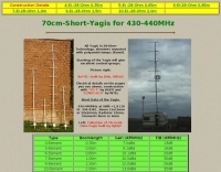
-
 The Flower Pot Antenna project details a portable dual-band antenna primarily operating on 10 meters, with secondary resonance near the 30-meter band. Construction involves winding RG58 coaxial cable uniformly around a large plastic flower pot, approximately 70cm high with a 60cm top diameter. The design eliminates the need for radials, contributing to its compact and lightweight nature. Key construction steps include soldering the inner conductor to the shield at one end of the wound cable and connecting the wound cable's shield to the rig cable's inner conductor at the base. An LC network, comprising a variable capacitor (0-200pF) and an inductor (10 coils, 5cm diameter, 2mm wire), is inserted between the wound cable's inner conductor and the rig cable's shield. Tuning is performed with an antenna analyzer, adjusting cable length and the variable capacitor for optimal impedance on 10 meters. The antenna performs effectively when installed horizontally.
 -
 Here is a high-performance hand-held beam antenna that is easy to build and guaranteed to improve your downlink from the LEO satellites over ANY rubber duck or mobile whip
 -
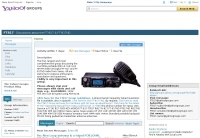 Members discuss the operation of and modifications to this outstanding QRP rig that covers 160m 70cm with all modes. Site contains a large database of FT-817 FAQs and data files. Antennas, tuners, and power sources are also covered as related to this ultra-compact transceiver.
 -
 Build your own antenna for the 23cm band ( 1250Mhz - 1280Mc ) using some aluminium and this simple design.
 -
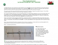 A suitable high gain 70cms antenna for SOTA operation by Richard Price GW0VMW
 -
 A portable antenna for mode B and J satellites
 -
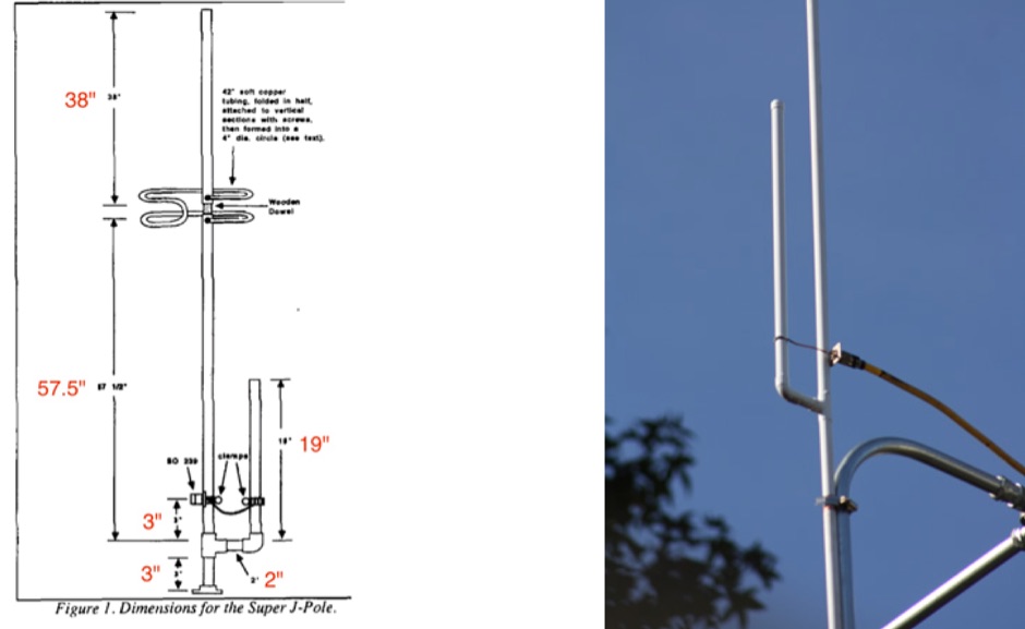 Homebrew a j-pole 2mt and 70 cm antenna project. Make it cheap. This article includes homebrewing instructions, parts lists, tools needed and printable documentation.
 -
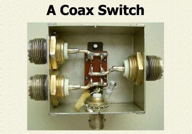 An inexpensive coax switch. shows a proven inexpensive home-made antenna selection switch. If you question the use of a cheap slide switch and SO239 coax sockets, read on. Measurements in a physics lab showed there to be practically no reflection on HF and even on 70 cm the SWR was below 1.3 : 1
 -
-
 An AO-10 antenna by K5OE, this design is optimized for 436.8 mHz with a 50 Ohm feed
 -
 Demonstrates a **DX cluster** web service providing real-time amateur radio spot reports, propagation information, and solar data. The platform integrates features such as a gray line map, **DXCC** tracking, and a personal logbook, allowing users to manage their confirmed entities and contacts. It supports various bands from 160m to 70cm, including specific filters for modes like FT8/FT4, and offers both web and Telnet access for spotting and monitoring. The service provides graphical representations of spot reports, detailing activity across different frequency bands and modes (CW, SSB, digital). Registered users gain access to advanced functionalities, including personalized filters and tools for calculating DXCC status. The platform also includes a classifieds section and options for mobile access, catering to a broad range of amateur radio operators interested in DXing and contesting.
 -

-
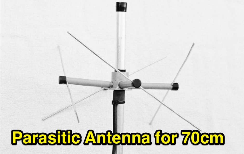 A Parasitic Lindenblad Antenna for 70cm by Anthony Monteiro, AA2TX. This is the official 16 pages PDF File published by AMSAT about the 70cm Parasitic Lindenblad Antenna.
 -
-
-
-
 PA3FWM's software defined radio (SDR) page documents his extensive hardware and software development efforts between 2004 and 2009. Initial experiments utilized a direct conversion receiver with 90-degree phase difference, feeding a PC soundcard at 48 kHz sample rate, covering 24 kHz of spectrum around a 7080.5 kHz local oscillator. This setup, similar to AC50G's QEX 2002 article, allowed for basic I/Q signal processing to distinguish signals above and below the LO frequency. Limitations included fixed crystal frequencies, 16-bit dynamic range, and narrow bandwidth. Subsequent hardware iterations aimed for enhanced performance, incorporating external 24-bit ADCs with 192 kHz sample rates, connected via 10 Mbit/s Ethernet. A **MC145170-based PLL** and programmable octave divider provided a 58 kHz to 30 MHz tuning range. The **Tayloe mixer** was employed, with differential outputs feeding a PCM1804 ADC. An ATmega32 microcontroller handled serial data conversion to Ethernet frames, though without CRC calculation due to processing constraints. Later designs integrated AD7760 2.5 Msamples/second ADCs and a Xilinx Spartan-3 FPGA, enabling direct reception of 0-1 MHz spectrum and eventually 2.5 MHz bandwidth across the shortwave spectrum. Software was refactored to use an initial 8192 non-windowed FFT for efficient high-bandwidth processing. The project culminated in a two-way QSO on 21 MHz using the developed hardware and software, demonstrating transmit capabilities with a D/A converter. The system exhibited a 2.5 MHz wide spectrum display and a zoomed 19 kHz display, capturing signals like ionospheric chirp sounders and RTTY contest activity. Challenges included noise leakage from digital circuitry and cooling for high-power dissipation components.
 -
 Designing a compact directional antenna for the 70cm band involves balancing gain, front-to-back ratio, and physical size. This resource details the construction of a 2-element Moxon rectangle antenna for 432 MHz, outlining the specific dimensions for the driven element and reflector, and discussing the advantages of its folded dipole configuration. The article provides insights into the historical context of 70cm operations and the author's personal experiences with early 432 MHz transceivers and antenna setups, such as a Jaybeam 48-element TV antenna. It also touches upon the practical aspects of building and deploying such an antenna for local and weak-signal work. The Moxon antenna design is compared to a 3-element Yagi, noting its superior front-to-back ratio and broader bandwidth for a given boom length, making it suitable for portable operations or restricted spaces. The construction uses readily available materials like copper wire and PVC tubing, emphasizing simplicity and ease of replication. Performance characteristics, including a reported gain of approximately 5.5 dBi and a front-to-back ratio of 20 dB, are discussed in the context of its compact footprint. The resource includes a visual representation of the antenna's dimensions and construction, aiding in practical implementation.
 -
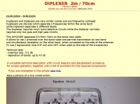 This DIPLEXER separates 2m from 70cm on the same coax cable, and allows to use 2 antennas over the same cable and permits transmission on one band and simultaneous receiption on the other band by hb9abx
 -
-
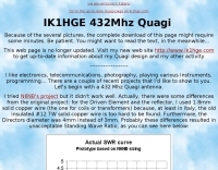 Quagi 8el 70cm improved 13.77dBi by IK1HGE
 -
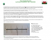 A suitable high gain 70cms antenna for SOTA operation was sought that did not have the drawbacks of a long Yagi antenna, principally a narrow beamwidth and bandwidth.
 -
 Constructing a compact UHF Moxon antenna for portable radio or TV applications demands a small, easily transportable aerial. This project focuses on a straightforward build method rather than a specific frequency design, leveraging _MoxGen_ software by AC6LA to derive precise dimensions. The author's approach utilizes an epoxy printed circuit board as the support, with traces drawn by a special felt-tip pen for soldering the antenna elements after an etching bath. For high-frequency work, particularly in the GHz range, the choice of insulating material is critical; the article emphasizes the necessity of quality UHF or SHF-grade insulation. A standard SMA connector is integrated, with one element making electrical contact via the nut and the other soldered to the central pin. This ensures a robust feedpoint for the coaxial cable. The coaxial cable, fitted with its connector, is threaded through a 12mm PVC tube that functions as a mini-mast. This tube also defines the antenna's forward direction, which should be aimed at the target signal. A sanitary clamp at the base of the tube secures it to a photographic tripod via its 7mm thread, providing a stable and portable mounting solution.
 -
-
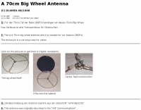 This is a 70cm big wheel antenna which is used at DB0FAI beacon
 -
-
 Constructing a compact, two-band magnetic loop antenna for HF operation, especially from constrained locations like a balcony, presents unique challenges. OK1FOU's design, inspired by DJ3RW's 50 MHz loop, addresses these by employing an unusual side-fed configuration and placing the symmetric, two-section variable tuning capacitor at the bottom of the loop, directly connected to the coax shield. The article provides specific material recommendations, including two 1-meter wooden pales and about 3 meters of thick loudspeaker cable, noting the high current (60A at 100W) in the loop. Construction steps detail forming two turns with a 5 cm gap, using a GDO to pre-tune the open loop to a frequency slightly above the desired highest band, and then integrating the tuning and coupling capacitors. For 10/14 MHz, an open loop resonance of 16-17 MHz is suggested. Practical experience with the 10 MHz band from a third-floor balcony in Prague (JO70GC) shows a 1:1 SWR across most of the band without an external ATU. While DX traffic was modest due to the urban environment, QSO examples with RA6WF, LA6GIA, G0NXA, and LZ1QK on 10 MHz are provided, demonstrating its operational capability.
 -
 The Discovery series of amplifiers are designed and built in the UK by Linear Amp UK Ltd, one of the world's leading amplifier manufacturers, specializing in high power RF tube amplifiers. The amplifiers use large GS31 or GS35 ceramic triode tubes. Band coverage 6m, 2m and 70 cms
 -
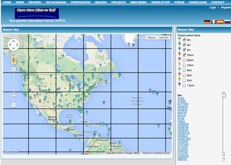 MMMonVHF maintains the data for 6m, 2m, 70cm and 23cm bands in collaboration to LA0BY. This site allow display of a beacon map and latest beacon spots.
 -
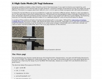
 Antenna was designed for SO-50 satellite operation but can be used for any VHF/UHF activity. It's a mix of a Moxon Antenna and a Yagi antenna. It has gains 4 dBd on 2m and 6.5 dBd on 70cm bands and it is fed via single 50 Ohm cable.
 -
-
-
 A _Topfkreis_ antenna, also known as a "bicycle pump" antenna, is presented as a simple vertical design for the 70 cm band. This variant of the J-pole antenna is notable for not requiring a ground plane, simplifying deployment. The construction details specify using aluminum tubing for the radiating element, with precise measurements for the quarter-wavelength outer tube (32 mm diameter) and the three-quarter wavelength inner sliding tubes (10 mm and 8 mm). Feeding is via a 50-ohm coaxial cable connected 90 mm from the base of the central tube. This design can achieve a gain of **4 to 6 dB** when properly tuned using the adjustable radiating element. The article details the fabrication of a critical aluminum washer, suggesting a method using a hole saw and a drill press as a lathe for precise adjustment. The illustrated example is specifically for the 70-centimeter band, and the author, Pop, clarifies construction points in the comments, including material choices and assembly techniques, ensuring a robust build for VHF/UHF operation.
 -
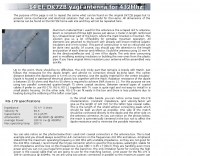
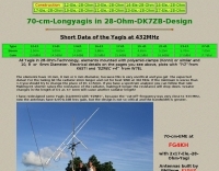
 Demonstrates the design and construction of a 9-element Yagi antenna for the **70 cm band** (432 MHz), based on the DK7ZB concept. The resource details EZNEC+ calculations for a single antenna, providing gain, sidelobe suppression, and front-to-back ratio figures. It also presents a comprehensive analysis of stacking two such antennas, including optimal stacking distance (1000 mm) and the resulting performance enhancements for the stacked array, such as an increased gain of 17.03 dBi. The article includes detailed drawings, wire file dimensions in millimeters, and azimuth/elevation plots for both single and stacked configurations. Practical construction steps are documented with original photographs, illustrating element mounting, the **28 Ohm matching system** using two quarter-wave 75 Ohm transmission lines, and the critical N-connector wiring. It also covers the iterative process of fine-tuning the driven element length to achieve a return loss of 20 dB, validating the EZNEC+ simulation results with actual measurements.
 -
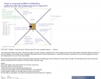
 The antenna is a vertical dipole, around which four parasitic elements are forming a circle.
 -
 The **70cm Moxon Beam** project outlines the construction and testing of a compact, directional antenna for the 432 MHz band. G3XBM recounts his early 1980s experience with a 4W FM321 transceiver and a Jaybeam 48-element TV antenna, which provided a baseline for his later UHF antenna experiments. This project focuses on a simpler, yet effective, design for local and regional contacts, emphasizing ease of construction and practical field results over complex theory. The article details the specific dimensions and materials used for the Moxon rectangle, including 6mm diameter aluminum tubing for the elements and a PVC boom. G3XBM notes that the antenna was built for portable use, making it lightweight and easily deployable for field operations. The feedpoint impedance was measured at 50 ohms, ensuring a direct match without the need for an external tuner, which simplifies setup. Performance tests included comparisons against a commercial 5-element Yagi, revealing that the Moxon provided comparable forward gain and an excellent front-to-back ratio, crucial for reducing local QRM. The author's observations confirm the Moxon's reputation as a robust performer for its size, suitable for both fixed and portable 70cm operations.
 -
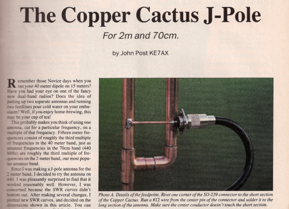 Original article published on February 1992 on 73 Amateur Radio Today about the 2m and 70 cm copper cactus J-pole antenna
 -

-