Search results
Query: attenuation
Links: 36 | Categories: 0
-
 ERP Calculator is an Amateur Radio software utility designed to perform a side-by-side comparison of two Ham Radio antenna systems. ERP Calculator comes pre-programmed with data files including published data for several popular brands and types of coax cable as well as several popular antenna system brands and models. ERP Calculator displays values of ERP, Antenna Power Gain, Antenna Feed point Power, Antenna System Gain in dB, Antenna Gain in dBd, SWR Attenuation in dB, SWR Power Attenuation, Coax Loss in dB, and Coax Power Loss
 -
-
 Various publications through the years have shown how the SWR measured on a shorted (or open) feed line can be used to calculate feed line attenuation
 -
 Industrial Communication Engineers (ICE) was a manufacturer specializing in **RF components** and solutions for amateur radio and commercial applications. Their product line included a range of RF parts, various types of filters, and RF switching products designed to enhance station performance and mitigate interference. These components were critical for hams engaged in contesting, DXing, or general operating, providing means to improve signal integrity and manage complex antenna systems. The company's offerings addressed common operational challenges such as RFI and TVI, with products like **low pass filters** and antenna filters. While the specific technical specifications of their product range are no longer available, such components typically provided significant attenuation of unwanted harmonics and out-of-band emissions, crucial for maintaining a clean signal and preventing interference with other electronic devices. The current status indicates the domain is for sale, suggesting the manufacturing operations have ceased.
 -
 Operating an 80/40/20M fan dipole for DX is analyzed through EZNEC modeling, focusing on the antenna's performance in a real-world, low-height installation. The resource details the physical construction and SWR measurements of the fan dipole, comparing them against EZNEC simulations. It also incorporates High Frequency Terrain Analysis (HFTA) data to illustrate typical DX elevation angles for various regions from New England, providing a crucial context for evaluating antenna patterns. The analysis presents EZNEC-generated azimuth and elevation patterns for each band (80M, 40M, 20M) at specific frequencies, showing gain figures at different elevation angles relevant to DX propagation. It compares the modeled SWR with measured SWR, attributing discrepancies to coax attenuation. The study concludes with observations on the antenna's azimuth performance (omnidirectional within ±1.5 dB) and its less optimal elevation gain at desired DX angles, highlighting the impact of low antenna height on DX capabilities.
 -
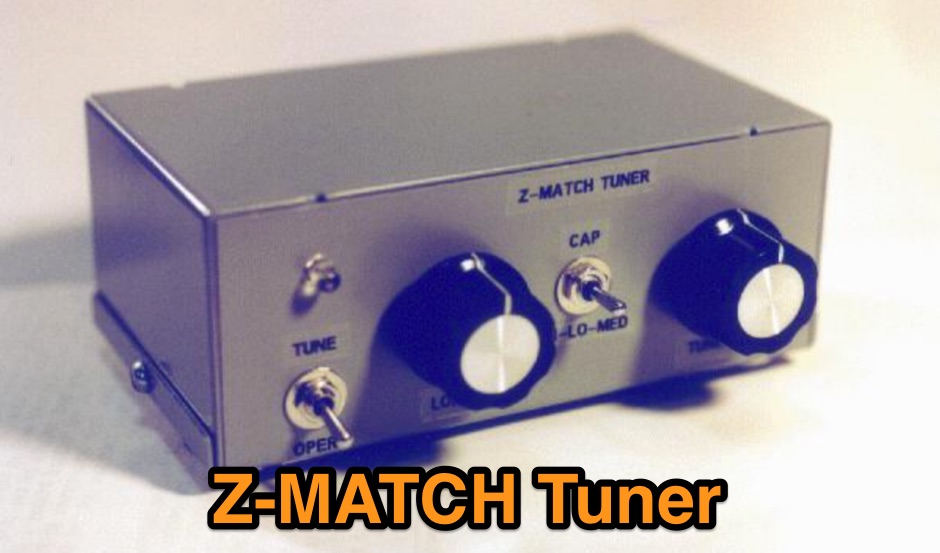 A home made antenna tuner based on the W6JJZ basic concept that ,atches balanced loads without the use of lossy baluns, can provide band-pass filtering and harmonic attenuation.
 -
 Stub sketch notes. Attenuation coax stub schematics
 -
 Hi-Z Antennas offers specialized high-impedance receiving systems, primarily focusing on phased vertical arrays for HF reception. Their product line includes preamplifiers designed for shortened vertical antennas, featuring optimized 15dB gain and array-matched characteristics. These components are engineered to enhance weak signal reception and improve signal-to-noise ratio across the HF spectrum. The company provides controllers for managing multiple vertical elements in a phased array configuration, enabling directional reception patterns. These systems are particularly effective for mitigating local noise and interference, a common challenge in urban and suburban operating environments. Specific offerings include solutions for 160-meter and 80-meter bands, addressing the unique requirements of low-band DXing. Technical details often reference components like the 2N3866 transistor in preamp designs and discuss concepts such as out-of-band attenuation. The focus remains on optimizing receiving antenna performance through impedance matching and active amplification, rather than transmit capabilities.
 -
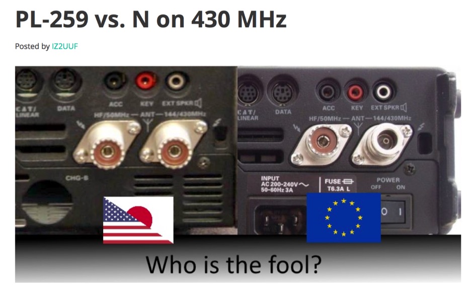 A test and comparison of real attenuation of N-type connectors and PL-259 connectors on UHF bands, domonstrating that connectors are almost equivalent.
 -
 Optimizing weak signal reception on the HF bands, particularly in the presence of strong local QRM, often necessitates specialized receiving antenna systems. This resource details the _HI-Z Antennas_ product line, focusing on phased vertical arrays designed for superior noise rejection and directivity. It covers components such as the 4-Square and 8-Element array controllers, which allow for rapid switching of receive patterns, and dedicated low-noise preamplifiers to improve system sensitivity. The site also presents various bandpass filters, crucial for mitigating out-of-band interference and enhancing the dynamic range of the receiver. The HI-Z systems are engineered to provide significant front-to-back and side rejection, often yielding **20-30 dB** of attenuation to unwanted signals, which is critical for DXing and contesting. Users can achieve a notable reduction in local noise, allowing for the discernment of signals that would otherwise be buried. The array controllers facilitate quick pattern changes, enabling operators to null out interference or peak weak signals from distant stations, effectively extending the reach of their receive capabilities by improving the signal-to-noise ratio.
 -
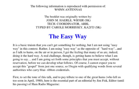 This document is a must read for anyone considering building a good low cost HF multi-band antenna system. The author combine in this document four important ingredients to produce simple but effective antenna system, like antennas of non resonant length, line attenuation, the transmatch and the balun
 -
 Two tables comparing several coax cables on attenuation and power ratings
 -
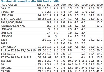
 The resource provides coaxial cable attenuation data, listing signal loss in dB per 100 feet for various cable types across a frequency range from 1 MHz to 5.8 GHz. The initial table details attenuation for cables such as _RG-58_, _RG-8X_, and RG-213, with impedance values of 50 ohm or 75 ohm, at frequencies up to 1 GHz. For example, _RG-58_ exhibits **0.4 dB** loss at 1 MHz and **21.5 dB** loss at 1 GHz per 100 feet. A subsequent table expands on this data, including LMR series cables like _LMR-400_ and LMR-600, along with other types such as 9913F7 and RG214. This section covers frequencies from 30 MHz to 1,500 MHz, also noting the outer diameter of each cable. For instance, _LMR-400_ (0.405" diameter) shows **0.7 dB** loss at 30 MHz and 5.1 dB loss at 1,500 MHz per 100 feet. The final section focuses on VHF/UHF/Microwave amateur and ISM bands, presenting attenuation in dB per 100 feet (and meters) for frequencies including 144 MHz, 450 MHz, and 2.4 GHz. This table includes larger diameter hardline options like 1/2" LDF and 7/8" LDF, in addition to flexible coaxial cables. For example, 1/2" LDF cable demonstrates **0.85 dB** loss at 144 MHz and 6.6 dB loss at 2.4 GHz per 100 feet. DXZone Focus: Coaxial cable attenuation | LMR-400 | RG-58 | 5.8 GHz
 -
 The collinear antenna, or Marconi-Franklin antenna, is an omnidirectional, high-gain antenna composed of in-phase half-wave dipoles aligned vertically. By using quarter-wave transmission line segments, it maximizes gain at a low horizon angle, outperforming a half-wave dipole. Adding segments increases gain but narrows bandwidth. A popular DIY version, the CoCo antenna, uses half-wave coaxial cable segments connected by non-radiating transmission lines. Built with stable velocity factor cables, a matching quarter-wave sleeve balun, and ferrite rings for attenuation, the antenna achieves performance comparable to commercial models.
 -
 1.5 dB of matched line loss can be calculated for a given transmission line using this online tool, which employs a model calibrated from empirical data. The calculator allows radio amateurs to input specific transmission line types, such as _RG-8_ or _RG-58_, and then determine the expected signal attenuation. This is crucial for optimizing antenna system efficiency and understanding power delivery to the radiating element, especially for HF and VHF operations where feedline losses can significantly impact performance. Beyond matched loss, the calculator also provides an estimate for mismatched loss if the Standing Wave Ratio (SWR) is specified. This feature helps operators quantify the additional power loss due to impedance discontinuities between the transceiver, feedline, and antenna, which is a common concern in amateur radio installations. Accurate loss calculations are vital for effective station design and for predicting actual radiated power. The tool's utility extends to various operating scenarios, from fixed station setups to portable deployments, aiding in the selection of appropriate feedline lengths and types to minimize signal degradation. Understanding these losses is a fundamental aspect of maximizing the effectiveness of any amateur radio antenna system.
 -
 Tables comparing attenuation of common coax cables on amateur radio bands
 -
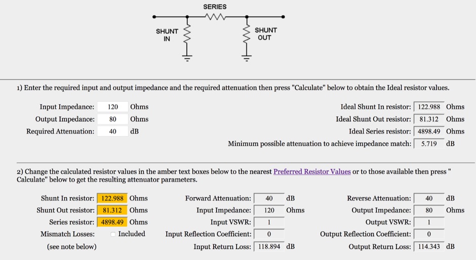 This is an on-line rf attenuator calculator provided free in order to promote the FLEXI-BOX. Calculates the resistor values, attenuation, minimum attenuation, impedance, reflection coefficient, VSWR and return loss of a matching Pi attenuator
 -
 The Kenwood TS-870S HF transceiver features two state-of-the-art 24-bit 20 MIPS DSP chips, providing over 100dB out-of-passband attenuation and CW bandwidth adjustable to 50 Hz. It operates across 160-10 meters with 100 watts output, incorporating digital filtering, a beat canceller, and 100 memory channels. The radio also includes a transmit equalizer, RX antenna input, and a K1 Logic Keyer, enhancing signal processing and operational flexibility for amateur radio operators. Advanced capabilities include IF stage DSP, dual noise reduction, and an auto notch filter, all contributing to superior signal reception and clarity. The TS-870S offers a variable AGC, voice equalizer, and an RS-232C port for computer control, with Windows™ software supplied. Its built-in automatic antenna tuner functions on all bands for both transmit and receive modes, streamlining station setup and operation. Available accessories such as the DRU-3A digital recording unit, SO-2 high stability crystal oscillator, and VS-2 voice synthesizer option further extend the transceiver's utility. The unit requires 13.8 VDC at 20.5 Amps and is supplied with an MC-43S hand microphone, making it a comprehensive station component.
 -
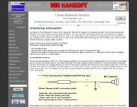 Demonstrates the fundamental principles for connecting a personal computer to a ham radio transceiver, specifically for utilizing sound card-based digital mode software like those in the MM Hamsoft suite. It details the basic hardware setup, emphasizing the use of shielded leads and proper audio routing from the radio's output to the sound card's input, and from the sound card's output to the radio's microphone or data input. The resource highlights the critical need for transmit attenuation, suggesting a 100:1 voltage divider to prevent overdriving the transmitter's audio stage, and mentions the optional addition of ferrite beads and decoupling capacitors for RFI mitigation. The guide also points to external resources for more detailed pin-outs and interface schematics, such as a specific QSL.net page, and recommends consulting the help files within MM Hamsoft programs for interfacing specifics. It underscores that while the process is straightforward, understanding the audio level management and proper cabling is key to successful operation. The author, VE5KC, provides practical advice drawn from common issues encountered by operators setting up digital mode stations.
 -
 The 40dB fixed attenuator is derived from two 20dB Pi attenuation pads
 -
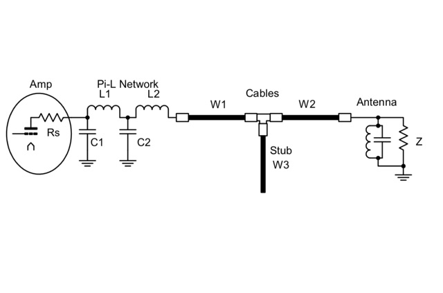 Optimizing the Performance of Harmonic Attenuation Stubs
 -
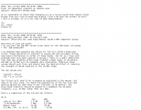
 A 0-30 MHz step attenuator, constructed from switchable Pi attenuation pads, provides a practical tool for evaluating receiver sensitivity and calibrating S-meters. The design utilizes readily available 5% tolerance resistors, with values derived from paralleled components to achieve specific attenuation steps. A schematic (Fig 1) illustrates the circuit, including PCB pad shielding, while a table details required and actual resistor values, along with percentage differences. Measurements of voltage input versus output at various frequencies are used to calculate dB attenuation, presented in a graph (Fig 4). The resource includes formulas for determining output voltage from a known input and a comprehensive 0-40 dB voltage multiplier table, which is crucial for precise signal level management. The project also references external attenuator calculators and equations for further study. Photos (1-3) provide visual guidance for the assembled unit, showing bottom, top, and front views. The project emphasizes the use of **Pi attenuation pads** and **receiver sensitivity** evaluation, offering a hands-on approach to RF signal management.
 -
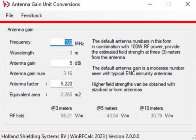 A multi tool Windows program that has been designed to offer the EMC RF and Radio Engineer a large variety of tools for Attenuation calculation, VSWR analysis, FIR Filter calculations, EMC system configuration, Radar testing , RF Filter calculation and much more without the need of a live internet connection.
 -
 The Linked Dipole is a multiband antenna designed for 80/60/40/30/20m bands, optimized for the (tr)uSDX low bands configuration. It incorporates a 1:1 Balun to prevent common mode currents, ensuring balanced operation with coaxial cable. The Balun, wound on an FT140-43 core, achieves 37-40dB attenuation. The design includes a 3D-printable housing for compactness and waterproofing, with labeled link insulators for ease of use. Wire lengths were meticulously adjusted for optimal performance with a 7m pole and 3m rope extension, ensuring the antenna's ends are off the ground for improved behavior. The project includes downloadable printables for DIY construction.
 -
 Messi & Paoloni offers a range of RF coaxial cables, including the _Ultraflex_ series, specifically engineered for amateur radio applications. These cables feature advanced dielectric materials and high-density braiding, resulting in significantly reduced attenuation across HF, VHF, and UHF bands. For instance, the Ultraflex 7 exhibits a loss of only **2.5 dB per 100 feet** at 144 MHz, making it suitable for demanding DX and contesting operations. The company's product line also includes specialized connectors, such as N-type and PL-259, designed to maintain optimal impedance matching and minimize signal reflections. Each connector is precision-machined to ensure a secure, weather-resistant termination, crucial for outdoor antenna installations and long-term reliability. Messi & Paoloni emphasizes rigorous quality control, with all cables undergoing testing to ensure consistent performance and durability, supporting effective two-way radio communication.
 -
 F5NPV introduces a variant of the W8JK antenna design, employing the MOXON principle. With extended monopoles, it outperforms the Open-Folded W8JK, yielding a 1dbd gain improvement, enhanced performance on 30m and 10m bands, bi-directionality, and lower side attenuation. The design's focus on higher radiation impedance results in increased antenna efficiency and reduced losses. Despite these improvements, the bill of materials remains unchanged.
 -
 Elecraft K2 mod. Narrower bandpass filter, better stopband attenuation
 -
 The video delves into the significance of interference reduction in ham radio setups by utilizing ferrite materials. It demonstrates the use of spectrum analyzers and tracking generators to showcase the performance of ferrite devices in minimizing noise levels. The analysis includes insights on resistance levels, attenuation factors, and the impact of using multiple ferrite clamps or rings to enhance noise reduction capabilities. Viewers gain a deeper understanding of ferrite composition, characteristic curves, and winding techniques for effective noise attenuation in different frequency ranges. Overall, the video serves as a comprehensive guide to optimizing interference reduction in radio environments through the strategic use of ferrite materials.
 -
 Operating an amateur radio station effectively requires reliable coaxial cable to minimize signal loss between the transceiver and antenna. SIVA Cavi, an Italian manufacturer, produces a range of coaxial cables, including specific 50 Ohm low-loss types suitable for amateur radio applications. Their product line features cables like **RG 58 SHF1**, **RG 213 SHF1**, and **RF 400 SHF1**, which are commonly deployed in HF and VHF/UHF setups. The company also offers specialized cables such as the **HF 214 UF Ultraflex**, a high-performance broadband low-loss 50 Ohm cable designed for flexibility and reduced attenuation across various amateur bands. These cables are engineered with solid or foam dielectric materials, impacting their electrical characteristics and suitability for different power levels and frequency ranges. For instance, foam dielectric cables often exhibit lower loss at higher frequencies, a critical factor for VHF/UHF operations. Beyond amateur radio, SIVA Cavi manufactures cables for digital video broadcast, offshore marine use, and fire detecting systems, demonstrating a broad engineering capability in coaxial cable technology.
 -
 The 222 MHz Transverter project, based on Zack Lau's (W1VT) original July 1993 QEX magazine design, provides an IF of 28 MHz for both transmit and receive paths. Rick Bandla (VE3CVG) contributed supplemental notes and construction details, including modifications to achieve 10 mW output power from an initial 4 mW PEP. The design incorporates three distinct boards: a Local Oscillator (LO), a Transmitter (Tx), and a Receiver (Rx), with an estimated parts cost of just over $150 CDN, significantly less than commercial kits. Construction involves both through-hole and surface-mount components, with specific guidance on mounting MAV and MAR devices, grounding techniques, and component selection. The project details include parts lists, schematics for the LO, Tx, and Rx, and board layouts. Troubleshooting advice emphasizes sequential testing, starting with the LO, then Tx, and finally Rx, using a 194 MHz and 222.100 MHz capable FM handheld for signal tracing. Further enhancements are discussed, such as an optional Tx driver stage to boost output to 100 mW and the potential modification of a Motorola Maxor 80 PA for 222 MHz SSB/CW operation. The resource also covers practical aspects like power attenuation pads for IF radios (e.g., FT817) and considerations for enclosure design, including repurposing a Maxor 80 case. Performance reports indicate successful 70 km contacts with only 4 mW output.
 -
 The PA0FRI Unbalanced/Balanced ATU is a home-built antenna tuner designed to efficiently match a W8JK 2-element beam antenna fed with a 450-ohm twin lead. Based on PA0FRI’s S-Match design, it optimizes energy transfer while maintaining balance, reducing losses, and ensuring proper radiation. The tuner uses a roller inductor, air variable capacitors, and a T200 iron powder coil, allowing fine-tuning across 14-50 MHz. Extensive lab tests confirm minimal attenuation and precise impedance matching, making it a reliable and efficient ATU for balanced antennas.
 -
 Learn how to enhance your 160 meter reception by building and using a custom band pass filter. Discover how this filter can reduce interference from strong AM broadcast signals, improving the overall performance of your receiver. Find out about the challenges of creating a filter that balances signal loss and attenuation at specific frequencies, and how it can benefit hams operating near powerful transmitters. Whether you're experiencing IMD issues or looking to optimize your 160 meter setup, this article provides practical insights and solutions for ham radio operators.
 -
 This project involved designing a 7-pole Chebychev broadcast band filter to address severe interference issues caused by a new horizontal loop antenna on the KN-Q7A transceiver. The interference overwhelmed the transceiver’s front end, so a custom filter with a 3.5 MHz cutoff was built using silver mica capacitors and type 6 T130 toroidal cores. Encased in a diecast box with SO239 sockets, the filter blocks strong signals from the broadcast band, achieving over 100 dB attenuation. Tested up to 100W, it reduces interference effectively while maintaining low insertion loss across HF bands.
 -
 This project documents the construction of a coaxial 50 MHz notch filter to eliminate inter-band interference between 50 and 70 MHz transceivers. Using RG-213 coax and based on quarter-wave stubs, the filter achieved a 44 dB attenuation at 50.060 MHz while maintaining low insertion loss on 70 MHz. A dual-stub design broadened the notch response and minimized attenuation on 70 MHz to 0.2 dB. Fine-tuned using an FA-NWT network tester and Elecraft XG3 signal source, the filter effectively resolved interference for seamless dual-band operation.
 -
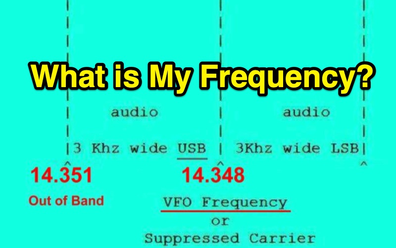 Single Sideband (SSB) operation requires careful attention to the relationship between a radio's displayed frequency (suppressed carrier) and the actual 3 kHz wide audio signal. This resource clarifies how Upper Sideband (USB) and Lower Sideband (LSB) signals occupy spectrum above or below the indicated frequency, respectively. It provides practical examples for General Class operators on the **20m** and **40m** bands, such as setting a VFO to 14.226 MHz for USB on 20m or 7.178 MHz for LSB on 40m, to maintain a safe margin from band edges. The resource emphasizes the critical importance of staying within allocated band limits to prevent out-of-band emissions, particularly when operating close to band edges. It includes relevant excerpts from **FCC Regulation Part 97**, specifically section 97.307, which details emission standards, necessary bandwidth, and spurious emission attenuation requirements. The text explains that unused sidebands are considered spurious emissions and notes that modern HF equipment typically exceeds the 43 dB spurious emission reduction standard, often achieving 60 dB or more.
 -
 The FF-501DX LPF, a high-performance VHF and 10m filter, was obtained at a friend's SK sale. After becoming more active on 10m, the author reexamined the LPF and discovered it to be of high quality. The filter's efficiency was outstanding and the return loss/VSWR was better than estimated. The LPF was connected to a Bird 50R dummy load to evaluate insert loss, cutoff, attenuation over 70MHz, and return loss. The original specifications were found in an old radio magazine, along with a link to the original one-page information sheet. Comparing the results to the original specs confirms the LPF's quality.