Search results
Query: copper hf antenna
Links: 24 | Categories: 0
-
 Demonstrates the construction of a **multi-band HF mobile antenna** utilizing a modified CB whip antenna base. The resource details the process of stripping a commercial CB whip, winding a new helical coil with 0.7mm insulated copper wire, and identifying tapping points for various HF bands. It emphasizes the importance of a rugged, slim design for mobile operation, discussing mechanical length, power handling (up to 200 watts), and coil diameter considerations. The article includes a graphic illustrating the antenna's operational principle, where sections of the helical coil are shorted from bottom to top to maintain efficiency and high Q. The resource presents a practical approach to achieving **band switching** without an external tuner, by manually adjusting tapping points on the coil. It provides a table with reference lengths in centimeters from the feedpoint for 7 MHz (40m) through 28.7 MHz (10m), including WARC bands. The author details mounting techniques, suggesting a Diamond bracket for secure attachment to a vehicle trunk, and stresses the critical role of proper grounding for optimal performance. The design allows for operation on 75m and 80m bands by adding a 110mm steel whip.
 -
 Build your mobile antenna which outperforms Hustler by 10db and ATAS-100 by 18db. From 80 to 10m. The HB9ABX mobile HF antenna, designed for 10 to 80 meters, was developed by Felix Meyer and outperforms commercial antennas like HUSTLER and YAESU ATAS-100/120 in field tests. Made from fiberglass rods and enamelled copper wire, it includes a loading coil with adjustable taps for tuning across bands. Installation requires solid grounding, and adjustments are made via whip length and coil settings. An antenna tuner ensures optimal SWR. Users must handle fiberglass with care due to health risks. This design proved highly effective in South America and Europe.
 -
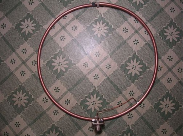
 The boomless quad antenna is a unique design that offers versatility for amateur radio operators. This antenna consists of two half-wave dipoles arranged in a square or circular shape, allowing for both vertical and horizontal polarization depending on the feed point. The design facilitates easy installation and rotation, making it suitable for various operating conditions. The construction utilizes strong materials, such as bamboo, and incorporates waterproofing techniques to enhance durability. This project outlines the necessary dimensions and materials, including copper wire and insulators, to successfully build the antenna. It emphasizes the importance of tuning each radiator element for optimal performance. The boomless quad is particularly effective across multiple HF bands, including 14 MHz, 21 MHz, and 28 MHz. By following the detailed instructions, operators can achieve a reliable and efficient antenna setup that enhances their DXing and contesting capabilities.
 -
 Conejo Valley Amateur Radio Club, article edited by Rory Eikland, KG6HCU and Ken Larson, KJ6RZ, they have had excellent experience building and using J-Pole antennas, and share their experience on planning VHF and UHF Jpole antennas.
 -
 The resource provides detailed information about a five-band indoor magnetic loop antenna designed for amateur radio operators. This antenna is capable of operating on the 20, 17, 15, 12, and 10 meter bands, making it a versatile choice for various HF communications. Constructed from a single 3-meter length of 22 mm copper tube, the design emphasizes compactness and efficiency, which is particularly beneficial for operators with limited space. The page includes insights into the construction process, tuning, and operational tips, catering to both novice and experienced users. In addition to the technical specifications, the resource also discusses the advantages of using a magnetic loop antenna indoors, such as reduced interference and improved performance in urban environments. It serves as a practical guide for those interested in building their own antenna, offering a straightforward approach to antenna design and construction. Overall, this resource is a valuable addition to the toolkit of amateur radio enthusiasts looking to enhance their station with an effective indoor antenna solution.
 -
 A simple dual band VHF UHF jpole antenna Projects by Dale Kubichek
 -
 Demonstrates the construction and performance of an updated ZS6BKW multiband dipole, a variant of the _G5RV_ antenna, specifically designed for HF operation. The article details a real-world installation using 13.5m copper wire elements and 12.2m of 450 Ohm ladder line, configured as a sloping inverted-V with the apex at 10m and ends at 4m above ground. It covers the critical aspect of impedance matching, incorporating an 8-turn choke balun at the feedline transition to RG-58U coax to mitigate RF common mode current. Measurements confirm favorable SWR readings below **1.3:1** on 7.1 MHz, 14.11 MHz, 18.06 MHz, and 24.8 MHz, indicating effective resonance across 40m, 20m, 17m, and 12m bands. The installation also shows usable SWR dips on 3.55 MHz (5:1), 29.02 MHz (2:1), and 50.84 MHz (3:1), extending its utility to 80m, 10m, and 6m with an antenna tuning unit. Initial on-air results report clear reception of stations over **5000km** away, validating its DX potential.
 -
 A 10-meter J-Pole antenna, detailed in QST February 1950, offers a straightforward solution for hams operating with restricted space. This design, originally presented by W1BLR, is a **half-wave radiator** fed by a quarter-wave matching stub, providing a low-angle radiation pattern beneficial for DX. The article describes building the antenna from readily available materials like copper pipe, emphasizing its simplicity and effectiveness for **single-band operation**. The J-Pole's inherent design provides a good impedance match to 50-ohm coaxial cable without the need for an external tuner, a significant advantage for portable or minimalist stations. Its nondirectional pattern ensures coverage in all directions, making it a versatile choice for general operating on the 28 MHz band. The construction plans are clear, allowing even those with basic workshop skills to assemble a functional antenna.
 -
 Constructing a **2-meter** J-pole antenna from readily available copper plumbing components offers a robust and cost-effective solution for VHF operation. This design, dubbed the "Plumber's Delight," functions essentially as a half-wave dipole fed by 50-ohm coax via a **gamma match**. It incorporates a quarter-wave copper tubing support, which, when affixed to a metal mast or tower, enhances forward power in the direction of the radiating elements. The original configuration utilized a small ceramic trimmer capacitor for the gamma match, suitable for up to 10 watts. A subsequent modification replaced this with a 50 pF variable capacitor housed in a plastic enclosure, accommodating higher RF power and improving weather resistance. The antenna elements are secured using a copper "T" fitting, and an SO-239 connector mounts directly to this fitting. Performance includes gain away from the support mast, and tuning is straightforward by adjusting the gamma match capacitor for a 1:1 SWR. The total cost for materials, excluding the capacitor and coax, can be under $10.
 -
 Constructing an HF End-Fed Half-Wave (EFHW) vertical antenna, the resource details the winding of a monoband matching unit, inspired by _AA5TB_, designed to provide a 50 Ohm impedance match without a ground plane or antenna tuner. It specifies the use of a _T200-2_ ferrite core for the transformer, outlining the 13-turn secondary and 2-turn primary winding process with enamelled copper wire. The document also describes the integration of a coax capacitor, whose length is critical for tuning and varies by band, with specific starting lengths provided for 20m, 17m, 15m, 12m, and 10m operation. The practical application section guides the builder through tuning the antenna using an antenna analyzer, emphasizing the iterative process of spacing secondary windings and trimming the coax capacitor to achieve resonance at the desired band frequency. It highlights the antenna's low angle of radiation, beneficial for DX, and claims up to 2 S-points improvement over a _G5RV_ or similar doublet when used as an omnidirectional vertical. A comprehensive shopping list, including specific part numbers from _Rapid Electronics_, is provided, along with advice on selecting fiberglass fishing poles for support and suitable antenna wire.
 -
 Autotena, a Taiwanese manufacturer, offers a diverse product line focused on RF communication antennas and related accessories. The resource details various antenna types, including **4G/3G LTE wideband high-gain low-profile antennas**, land mobile wideband antennas, fiberglass omnidirectional designs, and GPS mobile and marine antennas. Specific amateur radio offerings include NMO VHF load coil gain antennas, VHF whip gain antennas with PL-259 connectors, and UHF NMO mount antennas with 3dB/5dB gain. The company also produces antennas for CB and 10-meter amateur bands, such as aluminum broadband 26-30MHz antennas and big copper coil broadband 26-30MHz antennas. Additionally, the site showcases **RF amplifiers** for CB, HF, VHF, and UHF bands, including professional-grade base station amplifiers with 100% EIA duty cycle. Handheld antennas, PL-259 type mobile antennas, magnet mount antennas, and external CB speakers are also presented, alongside various mounting kits and cable assemblies.
 -
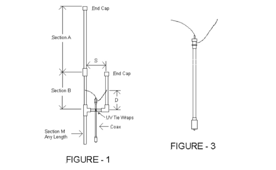
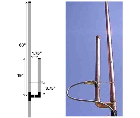
 Plans and drawings of common amateur radio antennas, like jpoles, copper cactus, super jpole, omnidirectionals and quads
 -
 Optimizing a G5RV or ZS6BKW multiband wire antenna for HF operation often involves addressing common SWR issues and understanding feedline characteristics. This resource chronicles the construction and performance evaluation of a G5RV, initially built for 80m, 40m, 15m, and 10m bands, by a newly licensed Foundation operator. The author details the selection of materials, including 3.5 mm stainless steel wire for the doublet arms and enameled copper wire for the open-wire feeder, and the initial decision to omit a balun based on common online information. The narrative highlights the initial disappointing performance, characterized by high receive noise and poor signal reports on 80 meters, despite the transceiver's internal ATU achieving a 1:1 match. This led to experimentation with a coax current balun and further research into G5RV myths, such as SWR claims and the necessity of a balun. The author then describes modifying the antenna to the ZS6BKW configuration, which involves specific changes to the doublet and feedline lengths, and integrating a 1:1 current balun wound on a ferrite toroid. The modifications resulted in improved reception and transmit performance across the bands.
 -
 One point eight MHz to 30 MHz is the operational bandwidth for this 4:1 Ruthroff voltage balun, designed to interface an unbalanced T-Match network with a balanced antenna system. The project details the construction using a _T200-2_ powdered iron toroid core, tightly wrapped in PVC electrical tape for insulation, and wound with 17 double bifilar turns of 1.25mm enamelled copper wire. This outboard balun offers flexibility, allowing hams to trial various baluns based on antenna system and impedance characteristics, rather than integrating it directly into the tuner. The resource includes a schematic of the balun, a wiring diagram showing winding connections, and a table suggesting alternative toroid cores like the T80-2 or T400-2 with corresponding winding counts. Component sourcing is straightforward, listing items such as the _Amidon_ T-200-2 core, SO-239 connector, and a sealed polycarbonate enclosure from Jaycar. Performance evaluation was conducted using an _AIM 4170C_ antenna analyser, demonstrating efficient 1:4 voltage transformation across the specified HF spectrum. Further efficiency tests involved measuring RF power loss at various frequencies, revealing minimal loss—less than 0.7 dB from 3.6 MHz to 30 MHz, and only 2.0 dB at 1.8 MHz. These measurements, performed under ideal 50-ohm conditions, confirm the balun's effectiveness as a low-loss interface for multi-band antenna systems. The page also links to several other balun and unun projects, including 1:1 current and voltage baluns, and 9:1 voltage ununs, providing a broader context for impedance matching solutions.
 -
 The ZS6BKW multiband antenna, an optimized variant of the classic G5RV, features a 102-foot (31.1 m) horizontal span and a 39.1-foot ladder line matching section. This design, derived by G0GSF (formerly ZS6BKW) in the early 1980s using computer programs and _Smith charts_, aims for improved SWR across multiple HF bands compared to its predecessor. Construction details specify Wireman 554 ladder line and #14 AWG THHN copper wire for the radiators, with precise instructions for determining the velocity factor (VF) of the ladder line using an antenna analyzer or dip meter, ensuring accurate physical length for the matching section. The radiator length is electrically 1.35 wavelengths for the 20-meter band, requiring careful trimming during tuning. Field measurements with an _AIM-4170C_ analyzer by KI4PMI and NC4FB demonstrated good SWR curves and bandwidth on 6, 10, 12, 17, 20, and 40 meters. The antenna was deemed unusable on 15 and 30 meters due to very high SWR, but an LDG AT-100PRO autotuner successfully brought 6 and 80 meters into tune. Contacts were made on 80, 40, 20, and 17 meters, including a **17-meter** contact to Spain. EZNEC models for 80-6 meters are provided, along with an AutoEZ model by AC6LA, which predicted good SWR for 80-10 meters. W5DXP's modifications for an all-band HF ZS6BKW are also referenced.
 -
 K1JJ presents a compilation of insights regarding vertical radial ground systems, specifically applied to 160m vertical arrays. The resource details 19 distinct observations and recommendations, emphasizing that ground radials primarily reduce ground losses rather than influencing pattern formation. It explains that RF current flows inefficiently through average soil, necessitating copper radials to create a low-resistance path back to the antenna base. The content suggests that **50-60 radials** are generally sufficient to achieve optimal efficiency, with diminishing returns beyond that number, and that radials should be laid on the surface for best performance. The discussion also addresses practical aspects such as wire gauge, installation techniques using 'U' shaped staples, and methods for connecting radials in multi-element arrays. It highlights the importance of radial length, stating that 1/4 wave radials are a crucial minimum, and that for 160m, radials should be at least _100 feet_ long. The resource critically examines the efficacy of elevated radials versus ground radials, noting that while a few elevated radials may suffice for VHF, HF applications, particularly on 160m, require extensive ground radial systems to efficiently collect RF currents in the near field. It also touches on the impact of radial systems on parasitic elements and the significance of symmetrical radial patterns for minimizing losses. Further practical advice includes wire type recommendations, proper soldering and weatherproofing techniques for radial connections, and considerations for integrating steel towers into the ground system. The author shares personal experience with installing 60 quarter-wave and half-wave radials under each of three in-line verticals, expressing satisfaction with the results.
 -
 A small, easy to build, copper tube magnetic loop antenna for the 2 meters band. In Italian
 -
 The simple balcony vertical HF antenna made with plastic fishing pole. Just along the pole I install copper wire in 7 meter length. Then was installed ATU. It was used home brew tuner. For each band was used one counterpoise in length 0.8 x lambda/4
 -
 Building an End-Fed Half-Wave (EFHW) antenna from a kit, as detailed by Frank Bontenbal, PA2DKW, with process photos by Bob Inderbitzen, NQ1R, offers a practical approach for hams. This specific kit, a collaboration between ARRL and HF Kits, targets 10, 15, 20, and 40 meters, making it a versatile option for HF operations. Unlike a center-fed dipole, the EFHW is a half-wavelength antenna fed at one end, which simplifies deployment, particularly for portable use. The construction guide meticulously outlines the assembly of the 49:1 impedance matching network, crucial for transforming the antenna's high impedance (around 2,500 Ohms) to a transceiver-friendly 50 Ohms. Steps include preparing the enclosure by drilling holes for the coaxial connector and antenna connections, followed by the precise winding of enameled copper wire onto a toroid to create the transformer. The guide emphasizes careful insulation removal and soldering for reliable connections. Final assembly involves integrating a 100 pF capacitor for higher band compensation, soldering the transformer's primary and secondary sides, and conducting SWR tests with a 2K7 resistor or a half-wavelength wire. The document also provides examples of wire lengths for different bands, such as 16 feet for 10 meters or 66 feet for 40 meters, demonstrating the transformer's adaptability for various half-wavelength configurations.
 -
 An homebrew HF Magnetic loop made with 2m length of 6mm diameter copper pipe formed into a near circle as the low loss inductor, a short length of coax as a capacitor,a short length of mains cable, again as a fixed tuned capacitor, a tunable 365pF air spaced capacitor, and a small Jackson C804 airspaced variable with a small 3-35pF trimmer in parallel
 -
 Pro Audio Engineering (PAE) supplies products for broadcast and amateur radio applications. The company manufactures heatsinks for _Elecraft_ **KX2** and **KX3** transceivers. PAE also produces AC power supplies for HF transceivers, remote power relays, and Ethernet relays. Machined products from PAE are manufactured in the **USA**. PAE distributes _Fair-Rite_ Mix 31 ferrite snap-it cores and toroid cores in various internal diameters. The product inventory includes commercial monitoring antennas, UQUI transformers, ULP AC power filters, and 3M conductive adhesive copper tape. Offerings also include the AM1 Portable Antenna Mount System. Pro Audio Group, LLC holds the copyright for the company as of 2024 DXZone Focus: _Elecraft_ | _Fair-Rite_ | Heatsinks | Ferrite Cores
 -
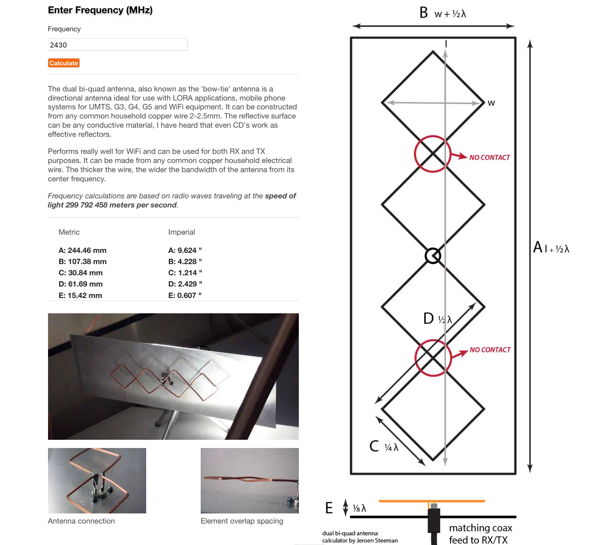 This webpage offers an online antenna designer tool to calculate the dimensions for constructing a double bi-quad antenna for various frequencies. The directional antenna is suitable for UHF and higher frequencies, such as WiFi, UMTS, LORA, and mobile phone networks. It provides dimensions based on the input frequency, making it ideal for hams looking to build their own antennas for specific applications. The tool also mentions using common household materials like copper wire for construction, making it accessible for amateur radio operators with basic equipment.
 -
 The Slim Jim VHF antenna, originally designed by G2BCX, is a folded half-wave dipole fed by a quarter-wave matching section. This version, built from a recycled professional aluminum dipole, demonstrates that various materials—such as copper, brass, or twin-lead—can be used. The article details the antenna’s construction, required materials, and tuning process, emphasizing mechanical stability and ease of assembly. With proper adjustment of the feed point, it provides excellent SWR across the band. Its durability and simplicity make it a practical and efficient VHF antenna solution.
 -
 This project outlines a simple, cost-effective 40m band HF dipole antenna design, ideal for beginners. Constructed with insulated copper wire and a 1:1 balun, it offers a 50-ohm impedance, suitable for both 40m and 15m bands due to the harmonic relationship. Calculations account for a K factor, ensuring optimal length and performance. Antenna modeling with 4NEC2 confirms practical access to both bands, though real-world results may vary. Lightweight materials and straightforward assembly make it an accessible and versatile amateur radio solution.