Search results
Query: element
Links: 528 | Categories: 3
-
 Build a space efficient trapped dipole antenna for 40-80-160 meter bands using RG-58 and PVC pipe. The document provides a brief guide on building a compact dipole antenna appropriate for the 40, 80, and 160-meter amateur radio bands. It explains the materials, building processes, and tuning methods required to provide best performance while preserving space. The paper also discusses theoretical elements of dipole antennas, such as impedance matching and feedline selection.
 -
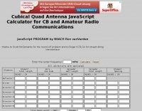 Cubical quad antenna calculator in java script let you calculate elements size and spacing in inch and meters.
 -
 Build this home made yagi antenna for your 2.4ghz wireless ethernet.
 -
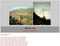
 This resource provides comprehensive instructions for constructing a 2 element quad antenna specifically designed for the 10, 12, and 15 meter bands. The antenna features a diamond configuration, which offers improved gain compared to a square configuration. The author shares insights into the materials used, including a square-aluminum boom and bamboo poles, along with construction techniques that ensure durability and optimal performance. This project is ideal for amateur radio enthusiasts looking to create their own antennas at home. In addition to construction details, the author discusses the antenna's performance, noting its effectiveness even at a height of 8 meters. The quad antenna reportedly performs comparably to a 3 element yagi, with excellent SWR readings and strong signal reports from European stations. This project is suitable for beginners and offers a cost-effective solution for those interested in enhancing their amateur radio setup with a homemade antenna.
 -
 Dissects the internal components of the popular _Antron 99_ vertical antenna, revealing its unique design elements. The analysis details the construction of the coaxial phasing sections, which contribute to its multi-band performance across 10, 12, 15, and 17 meters. Observations include the use of fiberglass tubing for weather protection and the specific arrangement of conductors within the antenna's structure. The examination highlights the antenna's reliance on a series of coaxial stubs to achieve resonance on multiple HF bands without external tuning. This internal architecture provides insights into how the _Antron 99_ manages impedance matching and radiation patterns for effective DX operation. Further details cover the antenna's base mounting and overall physical dimensions.
 -
 A simple design of a 9 elem. yagi antenna for 2 meters band
 -
 Details the construction of a **multiband vertical** antenna, specifically designed for stealth operation in a rented property, covering 80m, 60m, 40m, and 30m. The author, N3OX, leverages a 12m Spiderbeam telescoping fiberglass pole as the primary support, noting its sturdiness compared to typical fishing rods while remaining light enough for quick deployment and takedown. The radiating element is a 14 gauge Flex-Weave wire, attached to the pole's top with a rubber grommet, and fed by 27 bare 18 gauge radials spread across a 40-foot square backyard. N3OX describes the impedance matching solution, opting for custom-built L-networks over a remote tuner to enable fast bandswitching. Using an MFJ-259B and EZNEC modeling, base impedances were measured and component values calculated with G4FGQ's L_TUNER and SOLNOID_3 programs. The 80m coil is wound on a 3.5-inch PVC form, while the 30m, 40m, and 60m coils are air-wound, self-supporting #10 wire. Variable capacitors are incorporated for 40m and 30m shunt elements, with the 60m impedance matched by a series inductor. The project includes a **servo-controlled** homebrew band switch, utilizing a two-pole 12-position ceramic wafer switch for remote operation, addressing the limited 80m bandwidth. The entire matching network is housed in a weather-resistant shelter constructed from lumber and aluminum flashing. N3OX reports good DX results at 100W, estimating the total cost between $150 and $250, depending on existing parts.
 -
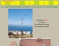
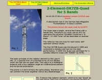
 2-Element parasitic Yagis for the Shortwave-Bands 10-12-15-17-20-30m. The antennas are feeded with the DK7ZB-match. A quarter-wave choke of coax is grounded at the socket.
 -
 The **Extended Double Zepp** (EDZ) antenna, a simple wire design, is presented as a means to achieve 3-4 dB of gain on 10 meters, with an overall length of just 43 feet. This resource, authored by WB3HUZ, details several gain antennas suitable for the 29 MHz AM segment, all modeled using EZNEC software at 30 feet above ground. Other designs include a compact rectangular loop, offering more gain than the EDZ and a lower take-off angle, and the **Lazy H**, a bidirectional antenna providing 6 dB gain, which is also workable on 20, 17, 15, and 12 meters. The Bisquare, a diamond-shaped open-top loop, is also featured, providing approximately 4 dB gain and requiring only a single support. These designs are primarily fed with ladder line or open-wire line to simplify matching, though a coax feed option for the EDZ is shown for 10-meter-only operation. The Lazy H, for instance, requires about 16 feet of open-wire line for its half-wavelength elements spaced a half-wavelength apart. An enhanced EDZ Lazy H variant is also discussed, achieving an additional 1-2 dB gain by extending element length to 1.28 wavelengths and increasing spacing to 0.64-0.75 wavelengths. The Bisquare, while primarily a 10-meter antenna, can be adapted for 20 meters by closing the top connection.
 -
 This PDF article from April 2001 QST details the construction of the "NJQRP Squirt," a reduced-size 80-meter inverted-V dipole antenna. The resource provides a general construction sketch, a photograph of the assembled antenna, and specific dimensions for PC-board insulators. The antenna consists of two wire legs, each approximately **34 feet long**, separated by 90 degrees, fed at the center. It is designed for operation on 80 meters (3.5-4.0 MHz) as a quarter-wavelength antenna, requiring a low-loss feedline and an external antenna tuner due to its non-resonant feedpoint impedance. Construction utilizes readily available materials, including 1/16-inch glass-epoxy PC board for end and center insulators, and #20 or #22 insulated hookup wire for the elements. The feedline specified is 300-ohm TV flat ribbon line, with a note on potential trimming for tuner compatibility. N2CX reports the antenna's center should be elevated to at least **20 feet**, with ends no lower than seven feet above ground, resulting in a ground footprint of approximately 50 feet wide. The design prioritizes NVIS propagation for local 80-meter contacts. DXZone Focus: PDF Article | 80m Inverted-V Dipole | Construction Notes | 34 ft element length
 -
 The QM7 antenna is a simple 7 elements Yagi with 3.7 m boom length for the lower 144 MHz SSB/MGM band, in PDF Format
 -
 Plans for 3 elements beam antenna and gamma matches
 -
 Details the construction of a J-vertical antenna specifically for the 10-meter band, offering a practical alternative to a _Slim Jim_ design for 28 MHz. The resource outlines the use of aluminum tubing for the half-wave vertical section and coaxial cable for the quarter-wave matching section, providing specific calculations for element lengths based on frequency and coaxial cable velocity factor. It contrasts the performance of the J-vertical with center-fed dipoles and end-fed verticals, noting superior results in previous comparisons. The article further presents a more recent iteration of the J-vertical, constructed using a fiberglass pole and insulated wire, with updated dimensions for 28.8 MHz. It includes practical advice on weatherproofing connections and securing the antenna for durability against adverse conditions, referencing the survival of an original _J Vertical_ during 110 MPH winds in 1987. The SWR performance is reported as 1.1:1 at 28.6 MHz, maintaining below 1.5:1 across 28.3 to 29 MHz.
 -
 The boomless quad antenna is a unique design that offers versatility for amateur radio operators. This antenna consists of two half-wave dipoles arranged in a square or circular shape, allowing for both vertical and horizontal polarization depending on the feed point. The design facilitates easy installation and rotation, making it suitable for various operating conditions. The construction utilizes strong materials, such as bamboo, and incorporates waterproofing techniques to enhance durability. This project outlines the necessary dimensions and materials, including copper wire and insulators, to successfully build the antenna. It emphasizes the importance of tuning each radiator element for optimal performance. The boomless quad is particularly effective across multiple HF bands, including 14 MHz, 21 MHz, and 28 MHz. By following the detailed instructions, operators can achieve a reliable and efficient antenna setup that enhances their DXing and contesting capabilities.
 -
 calculates the dimensions and spacings of the elements needed to build a log periodic antenna, given tao, sigma and the lower and upper cutoff frequencies.
 -
 40 Meter 2 element full size parasitic delta loop wire beam construction and switchable
 -
 The Cubical Quad antenna is a popular choice among amateur radio operators due to its robust design and excellent performance characteristics. This resource provides essential scaling formulas that help determine the lengths of the antenna elements and the necessary gamma match values for various frequencies. The design is adaptable, allowing operators to optimize for gain or front-to-back ratio by adjusting the spacing between elements. The accompanying Excel files facilitate precise calculations, making it easier for both beginners and experienced hams to construct their own Cubical Quad antennas. In addition to the design formulas, the resource includes practical insights from the author, who has successfully built and utilized these antennas in various field events. The document outlines the tuning process for achieving minimum VSWR, ensuring optimal performance. With detailed illustrations and performance data, this guide serves as a comprehensive reference for anyone looking to delve into Cubical Quad antenna construction and optimization, enhancing their amateur radio experience.
 -
 8 elements quad antenna for 2 meters band, centered on 145 Mhz
 -
 4 Element Cubical Quad, Yagis, LZA Circular Quad, Shrunken Quad , quarter wave, J-Pole, beam mounting , changing polarity
 -
 Build a portable VHF yagi antenna for 2 meters. All you need is two rabbit ear antennas from Radio Shack, two CATV baluns, four feet of 3/4 CPVC pipe with one tee.
 -
-
-
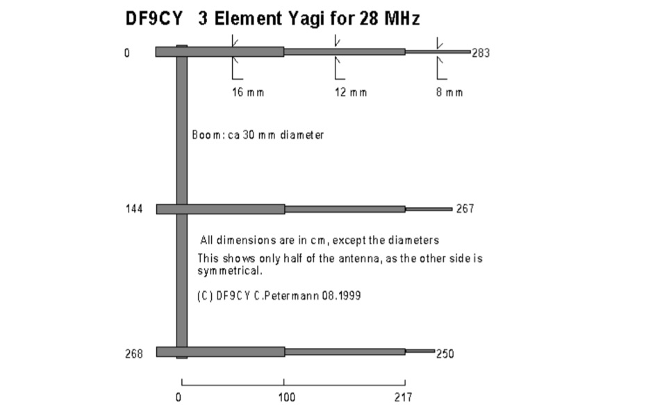 The DF9CY three-element antenna for 28 MHz by Christoph Petermann DF9CY
 -
 A JavaScript to calculate the dimensions for a seven element Yagi-Uda Antenna
 -
 The RXO Unitenna, a vertical wideband antenna, offers operation across the 7-21 MHz spectrum, covering the 40, 30, 20, 17, and 15-meter amateur bands. This design focuses on achieving a low SWR across a broad frequency range, making it suitable for general HF operation without requiring an external antenna tuner for minor SWR variations. The antenna utilizes a unique loading coil and matching network to maintain efficient radiation characteristics across its operational bandwidth. Construction details within the PDF document include specific dimensions for the radiating element and the counterpoise system, which is critical for vertical antenna performance. The design incorporates readily available materials, simplifying the build process for radio amateurs. Performance graphs illustrate the SWR characteristics across the 7 MHz to 21 MHz range, demonstrating the antenna's wideband capabilities. The document also provides guidance on feedline connection and grounding considerations for optimal field deployment. This vertical antenna configuration is particularly useful for hams with limited space, offering a compact footprint compared to horizontal wire antennas.
 -
 This is a vertical multiband antenna made up of several aerial elements lambda/4 length, feeded with just a coaxial cable in French.
 -
-
 Two well performing 50 MHz antennas designed with W7EL EZNEC along to many other antenna projects and related articles
 -
-
 Pictures comments and detail on a 2 elements antenna for 2 meters band
 -
-
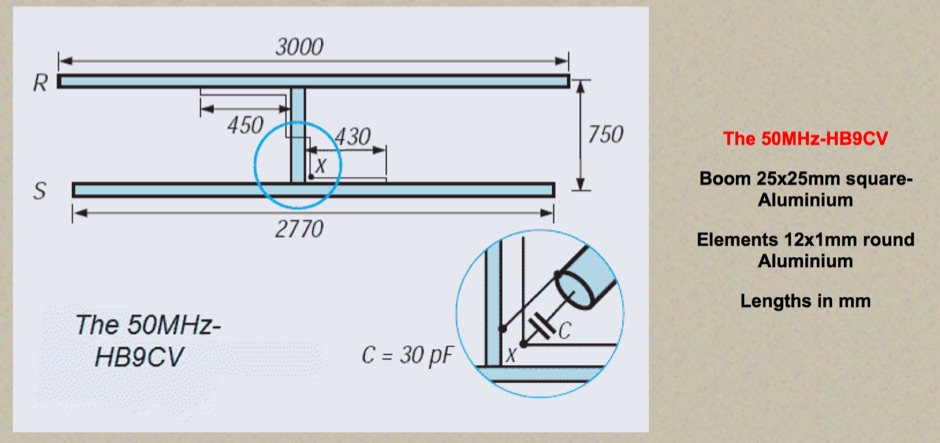 The HB9CV-Beam is a 2-Element-Yagi with two driven elements and was introduced by Rudolf Baumgartner, HB9CV in the 1950ies. This beam antenna is a coax-feeded version of the ZL-Special construction by DK7ZB for 2m, 6m and 10m
 -
 Details the construction and optimization of antenna systems for amateur radio satellite operations, focusing on practical, homebrew solutions for VHF/UHF bands. It covers building _groundplane antennas_ from salvaged materials, recycling old beam antennas into new configurations like a 2-meter crossed yagi, and constructing a 10-meter horizontal delta loop. The resource also explains antenna matching techniques, including folded dipole driven elements and quarter-wave transformers, along with the importance of accurate SWR measurements and minimizing coax loss. Demonstrates how to achieve a **1:1 SWR** by carefully trimming elements and adjusting radial angles on groundplane antennas. It provides insights into selecting appropriate coax and connectors, highlighting the benefits of Belden 9913 for low loss and the proper installation of _N-connectors_. The article also addresses RFI mitigation from computer birdies and presents a design for a silent triac antenna control circuit, offering practical solutions for common satellite station challenges.
 -
 The G3JVL 6 Meter ground plane vertical is a compact antenna that is ideal for portable operations. If needed, it can be disassembled into a very small bundle no longer than the longest element.
 -
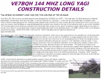
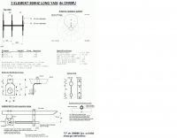
 If you want a top-performance VHF/UHF Long Yagi, you will probably have to build it yourself.
 -
 Presents a practical design for a **crossed-dipole turnstile antenna** specifically engineered for 2-meter Amateur Radio Direction Finding (ARDF) events. The author, WB6RDV, details a robust, omnidirectional, horizontally-polarized antenna, addressing the international ARDF rules requiring such characteristics at a height of two to three meters above ground. This contrasts with the vertical polarization often used in Southern California, highlighting the design's adherence to specific event requirements. The electrical design employs a classic crossed-dipole with a 75-ohm phasing section, resulting in a slight impedance mismatch and an SWR of approximately 1.3:1 with a 50-ohm feedline. Construction utilizes readily available and inexpensive PVC plumbing components and 1/8-inch bronze welding rod for elements. The guide provides step-by-step instructions for mechanical assembly, including drilling element holes at precise 90-degree spacing and preparing the RG-179 matching section. WB6RDV shares insights from his own build experience, discussing the use of plated brass versus aluminum spacers for element attachment and the effectiveness of crimping as an alternative to soldering. The document also covers final assembly, including the integration of ferrite beads as a choke balun and options for weatherproofing and alternative mounting configurations, emphasizing the adaptability of the design for other VHF bands through scaling.
 -
 This article describes how to make a quadrifilar helix (QFH) antenna easily, from inexpensive materials: uPVC plumbing pipe and RG-58U co-axial cable. A low-cost, easy-to-build Quadrifilar Helix (QFH) antenna for weather satellite reception using uPVC plumbing pipe and RG-58U coaxial cable. Unlike traditional designs requiring copper pipe and plumbing skills, this approach enables construction with basic tools and minimal technical expertise. The antenna's shorter, wider proportions favor higher elevation angles, reducing interference from horizon-level pager transmitters. Electrical connections are simplified at the antenna's apex, with the coaxial cable forming the radiating elements. Testing demonstrated consistent signal strength throughout satellite passes, proving effective weather satellite reception is achievable without precision engineering to sub-millimeter tolerances.
 -
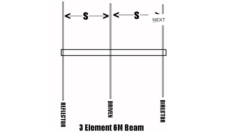
 Complete plans and drawings to build a small 3 elements Yagi antenna for six meter band by Ken Willis
 -
 Examines the operational differences between **quad** and **Yagi** antenna designs, focusing on their respective performance characteristics for amateur radio applications. The document highlights key metrics such as forward gain, front-to-back ratio, and bandwidth, which are crucial for effective DXing and contesting. It discusses how element configuration, boom length, and material choices impact the efficiency and radiation patterns of each antenna type across various HF bands. Practical considerations for antenna builders are addressed, including structural integrity, wind loading, and overall weight, particularly when using fiberglass spreaders for quads. The resource also covers precipitation static reduction in quads due to their closed-loop design and their ability to operate efficiently at lower elevations compared to Yagis. It provides insights into dual-polarization feed systems for quads, offering independent vertical and horizontal feed points for enhanced operational flexibility.
 -
 HF Wire Yagi antenna with notes and eznec file on original article of a Portable 3-Band Yagi antenna for 10-15-20 meter band made with wire elements. Include link the original to QST article.
 -
 10-12-15-17-20m A description was in the German Ham-Magazine "Funkamateur" in Issue 11/2003
 -
 The dipole antenna is an easily designed and made antenna usually used on HF, although can be (and sometimes is) made for VHF and UHF antennas, and in varying forms is also used as part of different designs of antennas i.e. as the driven element for directional antennas.
 -
 A wire yagi antenna for 20 and 40 meters band suitable for outdoor and field day operations
 -
 A new perspective on the analysis and design of this popular antenna element. By Karl-Otto Muller, DG1MFT
 -
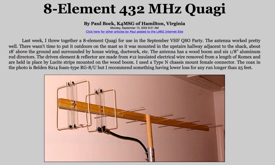 How to build a 432 Mhz Quagi, using a wood-made boom, and gives a 13 DBI Gain
 -
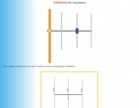
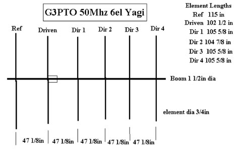 G3PTO antenna drawing plan for a 50MHz 6 Element Yagi beam
 -
 3 elements VHF Yagi homebrew antenna designed with YAGIMAX 3. Maximum forward GAIN is about 8,17 DBi. This antenna offering an effective radiation power 4 times greater of the transceiver output by SV1BSX
 -
 Presents the KE4UYP linear-loaded vertical antenna design, which introduces very little loss on 80 or 160 meters, achieving an overall radiation efficiency of 80% to 85%. This design addresses common pitfalls of traditional base-fed verticals by placing the majority of the current at the top of the antenna, eliminating the heavy reliance on extensive ground radial systems. The author's initial 10-meter model, only three feet tall, yielded 5/9 signal reports to Anchorage, AK, and Europe, confirming its effectiveness. The antenna incorporates both vertically and horizontally polarized radiators, with a 1/4 wavelength horizontal counterpoise located at the feed-point, near the top, to create an almost totally omnidirectional pattern with high wave angle horizontally polarized radiation. This dual polarization ensures even illumination across all take-off angles, making it effective for both local contacts and **DXing**. The vertical element is linear loaded, adding capacitance reactance and making it longer than the horizontal element to achieve resonance and raise the feed-point impedance to 50 ohms. Fine-tuning the antenna requires careful adjustment, as tower reactance can vary. The article suggests starting with 80 feet for 80m and 170 feet for 160m for the vertical wire, then trimming for resonance. Bandwidth specifications include 300 kHz under 2:1 **SWR** on 80m and 100 kHz on 160m when suspended between trees, or 150 kHz on 80m when side-mounted on a tower.
 -
 Pictures and plans of a 4 elements yagi beam antenna for 14 Mhz
 -
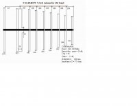
 A 3 elements long yagi antenna for 6 meters band by ON6MU