Search results
Query: four ty meter
Links: 25 | Categories: 0
-
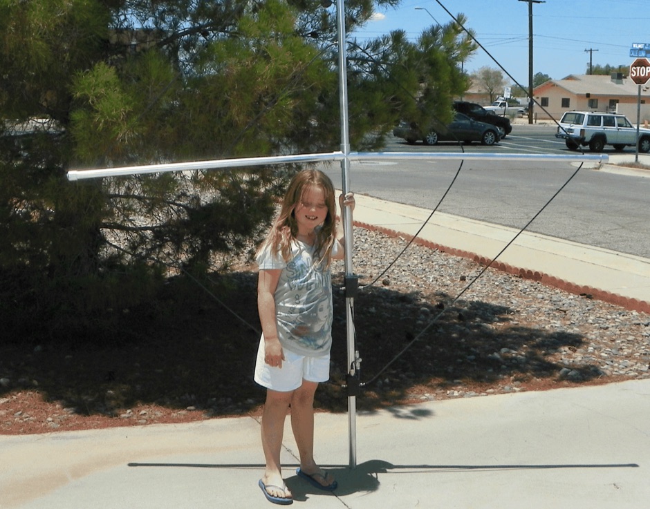 The 160/80m coaxial receiving loop antennas are designed to enhance reception on the top bands while minimizing noise. These antennas are particularly beneficial for operators with limited space, as they can be constructed using lightweight materials, making them portable and easy to deploy. The standalone 80m loop has a diameter of approximately four feet, allowing for easy rotation and installation above existing VHF antennas. Over the years, many amateur radio operators have turned to loop antennas as a viable alternative to traditional beverage antennas. The design allows for significant noise reduction, especially when paired with a quality pre-amplifier. Experimentation with various configurations has led to the discovery that diamond-shaped loops provide optimal performance. Users have reported a noticeable improvement in signal quality, making these loops a valuable addition to any low-band DXing setup.
 -
 Sixty-four years of operating experience inform Glynn E. "Buck" Rogers Sr., K4ABT's, insights into the J-Pole antenna, which he describes as a direct descendant of the _Windom_ or _ZEPP_. His first article on the J-Pole appeared in HRC magazine in 1958, and he has since published numerous pieces in publications like CQ Magazine, consistently referring to the J-Pole as a Windom with a folded-back short section forming the parasitic element. He emphasizes that both the Windom and J-Pole are powerful multi-band antennas, performing exceptionally well at harmonics of their fundamental design frequency, and advocates for 50-ohm coaxial cable with a _BALUN_ at the feed-point to avoid RF energy losses. K4ABT details the J-Pole's features, noting its ease of erection, lack of radials, low angle radiation, greater bandwidth, and immunity to terrestrial noise. He highlights its suitability for local nets and distant repeaters, claiming more gain and durability than most ground planes, and its ability to meet stealth antenna requirements. The guide provides specific dimensions for 2-meter (145.000 to 146.000 MHz) and 6-meter (50.500 to 51.500 MHz) J-Pole antennas, including measurements for the long driven element, short tuning stub, and spacing. The construction section illustrates a modified feed technique using an SO-239 chassis-mount coax connector soldered into a copper tee, deviating from the usual hose clamp method. The author also discusses the use of _EMT_ (electrical metallic thin-wall conduit) as an alternative to copper in earlier days. He cautions against building a 75-meter J-Pole due to its impractical length, reinforcing the antenna's optimal application for VHF and UHF bands.
 -
 The _Morgain_ antenna for 40/80 meters is a straightforward and cost-effective wire antenna design, requiring careful tuning for optimal performance across two bands with low SWR. Construction involves creating 12 cm PVC spacers with three holes for wire insertion, along with larger terminals for anchoring and connector housing, which should be sealed with silicone. The provided measurements detail the specific lengths for the antenna elements, crucial for achieving resonance on both 40m and 80m bands. Tuning the Morgain antenna necessitates fabricating four wire segments with pins to temporarily connect and adjust the bridging points symmetrically for both 40m and 80m. This iterative process, though time-consuming, ensures the antenna functions effectively for decades once the precise connection points are soldered and protected. The design emphasizes ease of construction and long-term stability, making it a practical solution for hams seeking a dual-band wire antenna.
 -
 The KD1JV "Melt Solder" Digital QRP SWR/Power Meter operates across the 160m to 6m bands, featuring 9.9-watt and 990-milliwatt power scales, a peak hold mode for SSB, and a VSWR scale from 1:1 to 9.9:1. It utilizes a _Stockton directional coupler_ wound on a single binocular core and an _Atmel AVR ATtiny26L_ microcontroller for processing. The design incorporates _W7EL diode compensation_ in a non-inverting amplifier feedback loop to address diode voltage drop and non-linear behavior at low power levels, with software corrections applied for improved accuracy, particularly at QRP power levels up to 5 watts. Construction details include parts placement, transformer winding instructions for #26 magnet wire, and calibration procedures using a 1.5V alkaline battery or an oscilloscope with a 50-ohm dummy load. Packaging options are discussed for fitting the board into an Altoids tin or a deeper Whitman’s Sampler tin, with considerations for battery life extension by adding a third or fourth battery. Accuracy tests performed at 7 MHz compare readings against a True RMS power meter based on an _Analog Devices AD8361_ chip, showing typical deviations of 0-5% across various power levels.
 -
 A **90-foot tall** top-loaded vertical antenna for the 160-meter band is detailed, constructed from aluminum irrigation tubing. The design incorporates four sets of four guy wires for structural stability, essential for an antenna of this physical size. This _monoband_ vertical is optimized for low-band operation, providing a robust solution for DXing and contesting on 1.8 MHz. The document includes specific construction methods for assembling the aluminum irrigation tubing sections and securing the guy wires. While a full NEC model is not explicitly provided, the physical dimensions and construction materials are sufficient for replication by experienced builders. The antenna's height and top-loading configuration are critical for achieving efficient radiation on 160 meters, particularly in minimizing ground losses.
 -
 The K5OE 2-meter vertical mobile antenna design, detailed in this resource, employs a 3/8-wavelength vertical section complemented by four shortened radials, forming an off-center-fed vertical dipole. This configuration creates a self-contained lower half, enhancing efficiency compared to traditional 1/4-wave monopoles relying on vehicle bodies for a ground plane. The article specifies construction using PVC components, 10-gauge insulated wire for elements, and provides precise dimensions in both inches and centimeters for the 25-3/16" (64 cm) vertical and 7-3/16" (20 cm) radials. Performance data indicates an honest 3 dBi of gain at 6 feet elevation (2 dBi free-space), with a pattern favoring the horizon, suitable for Low Earth Orbit (LEO) satellite communications. At 20 feet high, the same antenna exhibits almost 6 dBi of gain, with a nominal 50 Ohm feedpoint impedance at 146.850 MHz. Tuning instructions involve trimming element lengths, with the author achieving a 1.2:1 SWR by pruning the mast to 24-3/4" and radials to 7". The resource highlights the antenna's effectiveness for mobile LEO satellite uplinks, particularly at low elevations, and its suitability for fixed, mobile, or portable operations. The flexible wire elements allow for easy folding, making it a practical choice for backpacking. The original design by K5OE was previously hosted on aol.com.
 -
 Operational testing of a 10.07-meter portable HF vertical antenna, constructed from telescoping aluminum tubing (36, 32, 22, 17 mm diameters), yielded SWR measurements below 1.5 across multiple bands. Initial trials on 14.150 MHz showed an SWR of 1.6, while 7.075 MHz was problematic. Subsequent adjustments, including a 13 cm extension to the radiating element, improved performance, enabling operation on 6, 15, and 40 meters without a balun, and adding 12 meters with a balun. The design prioritizes portability, allowing transport in a standard vehicle and single-person deployment. Four 10.07-meter radials are connected at the base to enhance ground plane effectiveness. The article details the mechanical assembly, including custom adapters for tube transitions and a PVC sanitary tube sleeve for base insulation, ensuring robust field deployment. Final SWR measurements, documented with an _MFJ-259_ antenna analyzer, confirm operational ranges: 6.800-7.500 MHz (SWR < 1.5), 20.800-22.500 MHz (SWR < 1.5), and 48.800-51.500 MHz (SWR < 1.5) without a balun. With a balun, the antenna achieved SWR < 1.5 on 13.750-15.000 MHz and 24.890-28.350 MHz, demonstrating its versatility for portable _DXpeditions_.
 -
 This PDF document details the construction of a **70 MHz** Big Wheel antenna, a horizontally polarized omnidirectional array. The design utilizes three full-wave loops, each approximately **2160 mm** in diameter, arranged in a triangular configuration. The resource provides mechanical dimensions for the antenna elements and a comprehensive bill of materials, specifying component quantities and types, such as M8 stainless steel bolts, 15x15x1.5 mm square aluminum tubing for spacers, and 8 mm aluminum rod for the arcs. The central hub is constructed from two 160x160x8 mm aluminum plates, with four 40 mm long polyamide insulators supporting the radiating elements. The feed system incorporates a 50 mm diameter aluminum pipe for mounting and a matching stub constructed from a 120x20x2 mm aluminum sheet, connected via M8x10 mm bolts. The resource includes a diagram illustrating the mechanical dimensions and assembly points, including the N-connector fixing point and the center conductor attachment. The project was published on May 25, 2011, by Peter OE5MPL and Rudi OE5VRL. DXZone Focus: PDF | 70 MHz Big Wheel | Mechanical Dimensions | **2160 mm** loop diameter
 -
 Demonstrating the construction of a short dipole antenna tailored for the 60 meter band, this resource provides detailed instructions for radio enthusiasts with limited space. The design incorporates inductive loading using two inductors (L1/L2) made from PVC tubes, allowing for effective operation on 5 MHz. The antenna consists of 12 meters of wire, divided into four sections, with specific dimensions and materials outlined for optimal performance. Results from users indicate that this antenna can significantly enhance DXing capabilities on the 60 meter band. Feedback from operators suggests that while the design is effective, adjustments may be necessary based on individual setups, such as coil diameter and wire gauge. Many users report successful construction and operation, with some experimenting with variations to improve resonance. The practical application of this antenna design has led to successful contacts and improved signal quality, making it a popular choice among 60 meter band operators.
 -
 The W6NL Moxon Yagi is a high-efficiency two-element 40m Yagi that uses cross elements to provide both loading and Moxon coupling, addressing the challenge of deploying a directional antenna on the 40-meter band. This resource details the transformation of a _Cushcraft XM240_ Yagi into this Moxon configuration, replacing the original loading coil LCA sections with four new assemblies. The guide provides comprehensive instructions for building the boom and elements, including specific dimensions for new sections and tee loading elements, along with detailed drawings and a full parts list for the conversion. Performance data indicates the converted antenna achieves **10.73 dBi** gain at 7.050 MHz with 99.5% efficiency and a high front-to-back ratio. The VSWR bandwidth is over **300 kHz**, ensuring good performance across a significant portion of the 40m band. Construction involves reinforcing element sections, attaching tee loading elements with U-bolts, and implementing element guying using materials like _Phillystran_ to manage sag and maintain structural integrity.
 -
 Constructing a dip oscillator provides radio amateurs with a fundamental piece of test equipment for resonant circuit analysis. This particular design, adapted by VK3YE from a concept by _Drew Diamond VK3XU_, details a practical build using readily available components. The unit incorporates four plug-in coils, covering a frequency range from **2.6 MHz to 55 MHz**, mounted on 5-pin DIN plugs for versatility. A salvaged two-gang air dielectric variable capacitor, fitted with a vernier reduction drive, serves as the tuning mechanism, with the smaller gang optimizing bandspread at higher frequencies. In practical application, the dip oscillator is used by setting the meter needle to approximately two-thirds scale. When the instrument's coil is brought near a tuned circuit under test, a noticeable dip in the meter reading indicates resonance. This allows for precise measurement of resonant frequencies in antennas, filters, and other RF circuitry, proving invaluable for homebrewing and troubleshooting. The design emphasizes short wire runs for stable operation, particularly at the higher end of its operational range.
 -
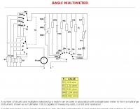 Constructing a basic multimeter involves integrating a 0-1mA meter movement with various shunts and multipliers, selected via a switch, to create a versatile instrument capable of measuring DC volts, current, and resistance. The design outlines two main units: a primary unit handling six DC current ranges up to 1 amp and eight DC voltage ranges up to 1000 volts, alongside an internal battery for an ohms range up to 200,000 ohms. This approach allows for a practical, hands-on understanding of meter operation. An add-on unit further extends the multimeter's capabilities, incorporating a meter rectifier and switched series resistors to provide four AC voltage ranges up to 100 volts. Additional shunt and series resistors, designated Ra and Rb, are included to expand the instrument's range to 10A and 5kV, demonstrating how modular design can enhance functionality. When this add-on is in use, the main instrument is set to measure 1mA FSD, connecting via specific lugs. Component selection emphasizes precision, with 1% tolerance high stability resistors for series elements and Eureka resistance wire for shunts. The design specifies values calculated for a meter with 60 ohms internal resistance, noting that these would require modification for different meter characteristics. Experimental adjustment of shunt values is recommended to ensure accurate readings against a calibrated reference meter, reinforcing practical calibration techniques.
 -
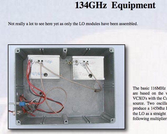 Developing operational amateur radio equipment for the 134 GHz band presents significant technical challenges, particularly in frequency generation and stability. This resource details the construction of a 134 GHz system, outlining its architecture with separate transmit (Tx) and receive (Rx) modules, each employing a local oscillator (LO) and RF head units. The system utilizes a dual Flann 50 GHz lens-type horn antenna configuration for optimal signal coupling. The transmit path incorporates an LMX2541 synthesizer chip operating at approximately 2.8 GHz, referenced by a 10 MHz double-oven Morion OCXO for exceptional stability. This signal is multiplied through a series of stages (X4, then X2) to generate a 22.4 GHz signal, which subsequently drives a dual series diode multiplier to produce the final X6 signal for 134 GHz operation. The receive side features an anti-parallel diode mixer coupled to a 144 MHz transceiver via a preamplifier, ensuring effective downconversion. Operational mode is CW, achieved by keying a multiplier stage. The project includes images of the Tx and Rx head units and describes a successful 3.5 km test with G8ACE, demonstrating stable signal tones due to PLLs locked to OCXOs at both ends, confirming the system's robust performance.
 -
 The PG7V Contest Calendar provides a curated listing of significant **HF contests**, with a particular focus on events relevant to European amateur radio operators. It details contest specifics such as start and end times in UTC, eligible bands (e.g., 80 meters, 40 meters, 10 meters), and required exchange information (e.g., serial number, CQ-zone, DOK, locator, age). The calendar includes diverse modes like CW, SSB, PSK63, RTTY, and FT4, catering to various operating preferences. Featured contests include the RSGB 80m Club Championship, WW WPX Contest, IARU Region 1 Fieldday, and ARRL International Digital Contest. Each entry links directly to the official contest rules for detailed information. The calendar also notes specific participation rules, such as the 1 KHz QSY requirement in the HA3NS Memorial Contest or the 24-hour single-operator time limit in the ARRL International Digital Contest. This resource is updated regularly, ensuring timely information for upcoming **contest operations** over a four-week period. It serves as a practical tool for hams planning their contest activity.
 -
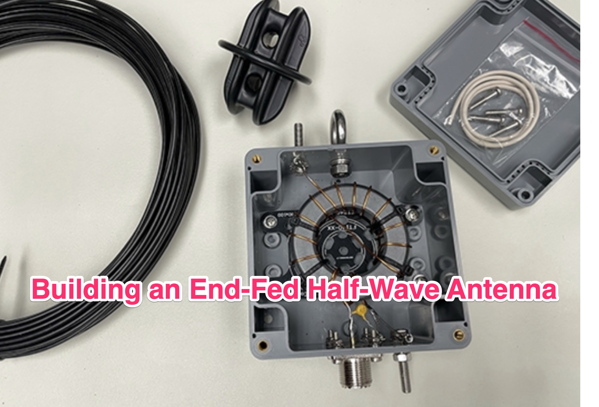 The ARRL's End-Fed Half-Wave (EFHW) Antenna Kit is an easy-to-build four-band antenna designed for 10, 15, 20, and 40 meters. Ideal for portable operations, it includes a 49:1 impedance transformer for compatibility with most transceivers. This project, detailed with step-by-step assembly instructions, involves creating a weatherproof enclosure and impedance matching network. The kit simplifies HF operations and supports multiple configurations, making it a versatile tool for amateur radio opertors.
 -
 Clarifies the intricate process of calibrating the _Elecraft K2_ dial, addressing common user challenges and lively discussions on the Elecraft reflector. Wilhelm, W3FPR, dissects the K2's PLL synthesizer design, chosen for its low phase noise, kit-friendly duplication, and cost-effective components. The resource emphasizes the critical role of the 4000.000 kHz reference oscillator's accuracy during CAL PLL, CAL FIL, and CAL FCTR functions, noting its dependence on temperature and crystal stability for optimal performance. Explaining the K2's frequency display, the document reveals it relies on microprocessor-driven look-up tables generated by CAL PLL for VFO values and CAL FIL for BFO values. In SSB and RTTY, these combine, while CW and CWr modes also factor in the sidetone pitch. The author details inherent limitations, such as the 10 Hz increment resolution of the dial and varying PLL step sizes—from 3 Hz on 160 meters to 10 Hz on 10 meters. BFO increments range from 20 to 35 Hz, collectively limiting practical dial accuracy to within **20 Hz** with diligent effort, or **30 Hz** for a slightly less demanding task. The guide outlines a four-step calibration procedure: setting the reference oscillator, running CAL PLL, running CAL FIL, and setting all BFOs. It highlights the _N6KR Method_ as a particularly easy and accurate approach, requiring only the K2 and a known frequency source like WWV for zero-beating, eliminating the need for external test equipment.
 -
 This blog chronicles the development of an 80-meter vertical antenna for amateur radio operation. The author constructs a top-loaded vertical using fiberglass poles, achieving significant performance improvements over their previous end-fed wire antenna. Comparative testing using the Reverse Beacon Network and on-air contacts demonstrates 8-10 dB gain on the east coast. The project evolved to include 40-meter capability through a modified design featuring a four-wire vertical cage, loading coil, and strategic guying system. Despite challenges with signal wobble during windy conditions, the vertical consistently outperforms the end-fed wire, particularly for reaching distant stations during nighttime propagation.
 -
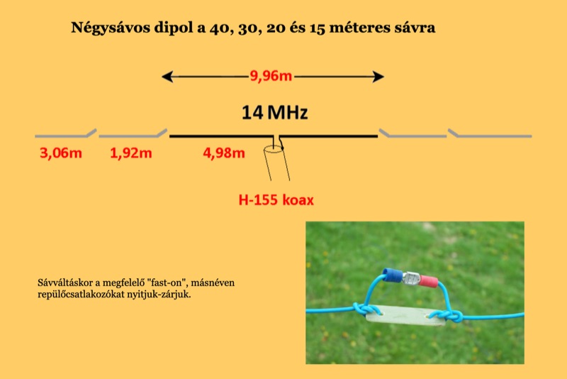 Four distinct amateur radio bands, specifically 40, 30, 20, and 15 meters, are addressed by a portable dipole antenna design. This antenna utilizes a manual switching mechanism, employing "fast-on" or flying connectors to change bands. The design is presented with an animated plan, illustrating how operators can adjust the operating frequency by opening and closing specific connections on the antenna elements. The resource describes a _4 savos dipol_ (4-band dipole) that can be shortened for specific band operation. It provides practical information for hams seeking to construct a versatile, multi-band wire antenna for portable operations or fixed station use. This design offers a straightforward approach to achieving multi-band HF capability without complex tuning units, making it suitable for field deployments like SOTA or POTA activations where rapid band changes are beneficial.
 -
 Demonstrates the construction and portable deployment of a 40-meter horizontal loop antenna, often referred to as a "Sky Loop" or "DX-Buster." The design adapts a full-wavelength horizontal loop for field use, eliminating the need for traditional insulators by employing four 5-meter heavy-duty _squid poles_ and metal post bases for support. This setup facilitates rapid assembly, crucial for portable operations, with the antenna wire length specified at approximately 43-45 meters for optimal 40-meter band performance. The resource details the specific construction methodology, including winding the antenna wire around rubber caps on the squid poles and securing it with electrical tape. It provides a parts list and assembly techniques, focusing on minimizing components for ease of transport and quick setup. The article, originally published in the February 2013 edition of the Central Coast ARC "Smoke Signals" magazine, reflects practical experience. This documentation offers a field-deployable 40-meter loop antenna solution, utilizing readily available components like fiberglass squid poles. It presents a practical approach for operators seeking a robust, portable antenna for the 40-meter band, emphasizing simplicity and efficiency in its design and deployment.
 -
 The 1/4 wavelength vertical antenna project, initially designed for 20 meters, has evolved into a versatile portable solution covering 10 through 60 meters. K0BXB details its construction, emphasizing a bottom-loaded design with a tapped loading coil and four 10-foot counterpoise wires. The author shares personal experiences and field results, including **18 QSOs** during a park activation on 17m and 30m with 10 watts, and a **2,435-mile** contact with a contest station in Bonaire on 20m using 5 watts. Comparisons are drawn to commercial offerings like the _Wolf River Coils TIA_ and _QRPGuys Triband Vertical_, highlighting the DIY antenna's small footprint, light weight, and ease of tuning for POTA activations. The resource includes insights into using test equipment such as the _NanoVNA_ for SWR optimization and discusses various radiator lengths, from 17-foot wire to a 102-inch whip, demonstrating adaptability for different portable setups. Construction tips cover coil winding, tap placement, and connecting feedlines and radials using common components.
 -
 This article details the development of an 80-meter antenna within the confines of a restrictive covenant community. Faced with limited space, the author explores various options before implementing a clever hybrid design: a short 30-foot vertical wire running discreetly down the building's exterior combined with a capacitive top hat installed in the attic. Computer modeling confirmed the superiority of capacitive loading over inductive loading, increasing radiation resistance from 6 to 14 ohms. The perimeter wire top hat, naturally supported by the attic structure, resonates effectively at 3.5 MHz. The system is completed with four buried 60-foot radials installed "after dark" to maintain compliance with community restrictions.
 -
 Details the construction of a portable 6-meter 4-element quad antenna, specifically designed for VHF and Field Day operations. The design emphasizes portability and rapid field assembly, utilizing a 10-foot boom, #12 bare wire elements, and fiberglass electric fence post spreaders. It presents specific dimensions for reflector, driven element, and directors, including spreader lengths, circumferences, and corner marks, all derived from a G0KSC design and modeled in EZNEC. The resource outlines the fabrication of synthetic lumber hubs that allow post-assembly adjustments along the boom, and describes spreader clamps made from ¾” OD fiberglass rod, drilled and tapped for 8-32 nylon thumbscrews to secure element wires. It provides instructions for reducing spreader ends to 0.370” OD for proper fit and details the assembly of the boom from two 1½” OD x 6’ aluminum tubes. Performance data from EZNEC modeling indicates a gain of 10.25 dBi (8.1 dBd) and a 20 dB F/B ratio at 50.150 MHz, with SWR values of 1.08, 1.09, and 1.11 at 50, 50.15, and 50.5 MHz respectively. The document includes a field test report from Field Day 2010, where the antenna was deployed at 21 feet, showing an SWR resonance 200 KHz below EZNEC predictions. It notes successful 5-watt QSOs into New York and Canada from Tennessee, highlighting the antenna's excellent directivity and gain compared to a 4 dBd Moxon. The antenna breaks down into easily transportable components, including two 5’ boom sections, a 3’ boom connector, 16 spreaders, and four element/spreader clamp assemblies.
 -
 Details the installation and operation of the DX Engineering TFS Series Transmit Four Square System Phasing Units, specifically models like the DXE-TFS4-160B, DXE-TFS4-80B, and DXE-TFS4-40B. It covers system components, required parts, and a discussion of vertical antenna selection, including a table of suitable DX Engineering Monoband Vertical Antennas. Installation procedures are outlined, encompassing site selection, four square layout, topographical considerations, and noise source mitigation. Specific instructions are provided for mounting the phasing unit, antenna feedline connections using 1/4-wave 75-ohm coaxial cables, and control wire routing. The document also includes details on radial system implementation, with a table of radial wire lengths for 160, 80, 75, and 40 meters, and procedures for tuning the vertical antennas for optimal performance. Operational aspects of the Four Square Control Console are described, including front and rear panel functions, control logic (Table 4), and typical transceiver/amplifier interconnections. The system enables directional control with approximately 5 dB gain over a single vertical element in four directions or an omni-directional pattern, achieving typical front-to-back ratios exceeding 20 dB. Lightning protection and initial system testing are also addressed, along with a 5 kW CW and 10 kW PEP SSB power rating and hot switching lockout feature.
 -
 The Spartan Sprint Special 40m CW Transceiver, originally documented in 2002 and reproduced in 2019, details a **QRP** direct conversion rig designed for portable operation. This project evolved from an experimental CMOS digital IC receiver, which proved too noisy for weak signals, into a dedicated 40-meter CW transceiver. The author, VE3SMA, aimed for reduced size, lower weight, and decreased receive current drain compared to earlier iterations, drawing on his extensive contesting experience and even his time operating million-watt transmitters at Radio Canada International. This compact transceiver delivers approximately 200 mW output, VFO-tunable over 15 kHz within the 40m band, and weighs a mere 73 grams (0.16 lb) including its balsa wood case. It features fast semi-break-in and sidetone, with a receive current draw of about 14 mA (no signal) and transmit current draw around 125 mA key down. The design incorporates various construction techniques, including knife-cut surface mount boards and through-hole components, often salvaged from junked cordless phones and cellphones. Despite its direct conversion architecture, which offers usable but not superheterodyne-level selectivity, the rig proved effective, achieving a fourth-place finish in a June 2001 Spartan Sprint contest when paired with a 26-foot vertical antenna. The article provides comprehensive circuit details, including an unconventional VFO using a high-speed CMOS inverter chip and a balanced mixer utilizing a 74HC4053.
 -
 Presents the RI8KR RRA Island Hoppers DXpedition, detailing its schedule from August 21 to 28, 2026, and its objective to activate four new island groups in the Ob Bay of the Kara Sea. The expedition targets specific Russian River Club (RRC) references: RR-06-66 (Ob River Delta Islands West), RR-06-67 (Ob River Delta Islands North-West), RR-06-68 (Ob River Delta Islands North), and RR-06-69 (Ob River Delta Islands Center/North). Operators Vladimir, RK8A, and Igor, UA3EDQ, will operate on 40, 30, 20, 17, 15, 12, and 10-meter bands using CW, SSB, and potentially Digital modes. Three of these activations contribute to IOTA AS-109, an entity not activated since 2013. The page provides QSL information via RZ3EC (Eugene Shelkanovtsev, P.O. Box 70, Orel 302028) and online platforms including RRAWARD.RU, LoTW, RDAWARD.RU, and CFMRDA.RU. It lists supporters of the expedition, acknowledging contributions from various amateur radio operators. Recent updates confirm the purchase of airplane and boat tickets for the team's travel to Salekhard and Salemal/Panayevsk, indicating active preparation for the August 2026 operation.