Search results
Query: pll
Links: 14 | Categories: 0
-
 The Elecraft K3, a popular HF transceiver, is often benchmarked against new market entrants. This article critically compares the Kenwood TS-590S to the K3, focusing on key technical specifications and operational aspects relevant to serious amateur radio operators. The author proposes three distinct evaluation methods: a circuit diagram comparison, an independent review analysis (referencing Peter Hart, G3SJX, in RadCom), and a real-world "ear test" by experienced contest operators on 40 and 80 meters. The analysis delves into specific receiver components, including the first mixer design, RF and IF amplifier performance, and the presence of an image noise filter. It highlights the K3's switched mixer and the potential for the TS-590S to utilize similar or improved designs, such as a classic filter with enhanced selectivity. The article also scrutinizes the second mixer stage, noting the K3's SA612 chip and its associated IP3 limitations, suggesting Kenwood might achieve benefits with a different mixer architecture. Further points of comparison include DSP capabilities, where the K3's high-performing DSP with KK7P's involvement is noted against the TS-590S's potential reliance on newer IC technology but possibly less refined software. The discussion extends to DDS and PLL implementations for phase noise and spurious emissions, and the utility of a second receiver for DX chasing and contesting, acknowledging its importance for some operators while being less critical for others. The article concludes by emphasizing personal preference in equipment selection.
 -
 PA3FWM's software defined radio (SDR) page documents his extensive hardware and software development efforts between 2004 and 2009. Initial experiments utilized a direct conversion receiver with 90-degree phase difference, feeding a PC soundcard at 48 kHz sample rate, covering 24 kHz of spectrum around a 7080.5 kHz local oscillator. This setup, similar to AC50G's QEX 2002 article, allowed for basic I/Q signal processing to distinguish signals above and below the LO frequency. Limitations included fixed crystal frequencies, 16-bit dynamic range, and narrow bandwidth. Subsequent hardware iterations aimed for enhanced performance, incorporating external 24-bit ADCs with 192 kHz sample rates, connected via 10 Mbit/s Ethernet. A **MC145170-based PLL** and programmable octave divider provided a 58 kHz to 30 MHz tuning range. The **Tayloe mixer** was employed, with differential outputs feeding a PCM1804 ADC. An ATmega32 microcontroller handled serial data conversion to Ethernet frames, though without CRC calculation due to processing constraints. Later designs integrated AD7760 2.5 Msamples/second ADCs and a Xilinx Spartan-3 FPGA, enabling direct reception of 0-1 MHz spectrum and eventually 2.5 MHz bandwidth across the shortwave spectrum. Software was refactored to use an initial 8192 non-windowed FFT for efficient high-bandwidth processing. The project culminated in a two-way QSO on 21 MHz using the developed hardware and software, demonstrating transmit capabilities with a D/A converter. The system exhibited a 2.5 MHz wide spectrum display and a zoomed 19 kHz display, capturing signals like ionospheric chirp sounders and RTTY contest activity. Challenges included noise leakage from digital circuitry and cooling for high-power dissipation components.
 -
 Portuguese page, from VLF to some GHz, antennas, projects, EME, NDB DX and more.
 -
 It is a application which can be used for troubleshooting CB radio faults, by giving a graphical display of the normal operating frequencies generated by various parts of the CB radios circuits, it can help you identify if a frequency is incorrect or even missing. Another good use for this software is simulating possible frequency expansions, as it allows you to choose any frequency that the PLL is capable of generating, so you can see what the radio will allow you to get !
 -
 A microphone preamplifier schematic for hand-helds by ON6MU
 -
 A synthesized 2.3 GHz Amateur Television (ATV) transmitter design, conceived by Ian G6TVJ, is presented, targeting broadcast-quality video performance on the 13cm band and extending up to 2.6 GHz. The core of the design utilizes a commercial Z-comm Voltage Controlled Oscillator (VCO) that tunes from 2.2-2.7 GHz, providing a +10 dBm output and simplifying RF alignment. This VCO's stability, originally intended for narrowband applications, readily accepts high-frequency video modulation, contributing to the transmitter's robust performance. The exciter stage, incorporating a Mini Circuits VNA 25 MMIC amplifier, boosts the signal to +16dBm, while a Plessey SP4982 prescaler divides the output frequency for the synthesizer. The synthesizer employs a Motorola MC145151 CMOS parallel IC, favored over the common Plessey SP5060 for its superior video modulation characteristics and ease of programming without microprocessors. This choice addresses issues like LF tilt and distorted field syncs often seen with SP5060 designs, particularly when operating through repeaters or over long distances. The MC145151 divides the signal further, enabling precise frequency stepping, with programming handled by EPROMs for channel selection and LED display. The loop filter network, critical for video integrity, was developed through experimentation to prevent the PLL from reacting to video modulation, ensuring a clean transmitted picture. The transmitter incorporates a Down East Microwave commercial power amplifier module, delivering approximately 1.6W output, driven by the exciter through a 3dB attenuator. Construction involves surface-mount SHF components on micro-strip lines etched onto double-sided fiberglass board, housed within a tinplate box. The design boasts no AC coupling in the video path, preserving low-frequency response, a common failing in other ATV transmitters. Performance tests with a 50Hz square wave revealed no LF distortion, and a calibrated "Pulse & Bar" signal showed a near 100% HF response, demonstrating its capability for high-quality ATV transmissions.
 -
 Amplifiers, filters, attenuators, mixers, PLL, switches and frequency dividers, signal generators, power detectors, transimpedance amplifiers, variable gain amplifiers and more
 -
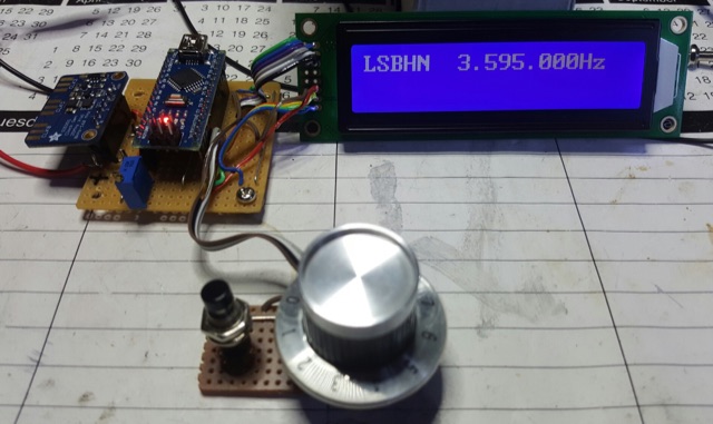 A kit Digital VFO with pre-soldered surface mount parts and burned-in firmware, a scratch build with Arduino Nano, C code with modifications, and a Silicon Labs si5351 PLL clock generator on a breakout board.
 -
 Constructing a high-performance RF spectrum analyzer up to 1000 MHz requires careful attention to component selection, shielding, and circuit isolation. This resource details a project that improves upon the _Spectrum Analyzer for the Radio Amateur_ design by Wes Hayward (W7ZOI) and Terry White (K7TAU), incorporating ideas from Scotty Sprowls' project, particularly his 1013.3 MHz IF bandpass cavity filter. The analyzer utilizes a Mini-Circuits SRA-11 mixer with a sweeping local oscillator from 1013 to 2013 MHz, feeding into a 4-pole copper pipe cavity filter. The design employs a second SRA-11 mixer with a fixed 1024 MHz LO to produce a 10.7 MHz final IF. This signal then passes through narrowband resolution filters and is processed by Analog Devices AD603 and AD8307 ICs for IF amplification and logarithmic detection, driving an oscilloscope in X/Y mode. The project emphasizes modular construction, using salvaged components and double-sided FR4 material for PCBs, with critical notes on minimizing spurious images through effective shielding and proper voltage regulation for each module. Key components include a Z-Communications V585ME48 VCO for the first LO and a Z-Comm V583ME01 VCO controlled by a Motorola MC145151 PLL for the second LO. An optional Hittite HMC307 step attenuator and K&L 5L121-1000/T5000-O/O low-pass filter manage RF input. Tuning procedures for the 10.7 MHz IF resolution filter are also detailed, showing before-and-after spectrum views.
 -
-
 Developing operational amateur radio equipment for the 134 GHz band presents significant technical challenges, particularly in frequency generation and stability. This resource details the construction of a 134 GHz system, outlining its architecture with separate transmit (Tx) and receive (Rx) modules, each employing a local oscillator (LO) and RF head units. The system utilizes a dual Flann 50 GHz lens-type horn antenna configuration for optimal signal coupling. The transmit path incorporates an LMX2541 synthesizer chip operating at approximately 2.8 GHz, referenced by a 10 MHz double-oven Morion OCXO for exceptional stability. This signal is multiplied through a series of stages (X4, then X2) to generate a 22.4 GHz signal, which subsequently drives a dual series diode multiplier to produce the final X6 signal for 134 GHz operation. The receive side features an anti-parallel diode mixer coupled to a 144 MHz transceiver via a preamplifier, ensuring effective downconversion. Operational mode is CW, achieved by keying a multiplier stage. The project includes images of the Tx and Rx head units and describes a successful 3.5 km test with G8ACE, demonstrating stable signal tones due to PLLs locked to OCXOs at both ends, confirming the system's robust performance.
 -
 Clarifies the intricate process of calibrating the _Elecraft K2_ dial, addressing common user challenges and lively discussions on the Elecraft reflector. Wilhelm, W3FPR, dissects the K2's PLL synthesizer design, chosen for its low phase noise, kit-friendly duplication, and cost-effective components. The resource emphasizes the critical role of the 4000.000 kHz reference oscillator's accuracy during CAL PLL, CAL FIL, and CAL FCTR functions, noting its dependence on temperature and crystal stability for optimal performance. Explaining the K2's frequency display, the document reveals it relies on microprocessor-driven look-up tables generated by CAL PLL for VFO values and CAL FIL for BFO values. In SSB and RTTY, these combine, while CW and CWr modes also factor in the sidetone pitch. The author details inherent limitations, such as the 10 Hz increment resolution of the dial and varying PLL step sizes—from 3 Hz on 160 meters to 10 Hz on 10 meters. BFO increments range from 20 to 35 Hz, collectively limiting practical dial accuracy to within **20 Hz** with diligent effort, or **30 Hz** for a slightly less demanding task. The guide outlines a four-step calibration procedure: setting the reference oscillator, running CAL PLL, running CAL FIL, and setting all BFOs. It highlights the _N6KR Method_ as a particularly easy and accurate approach, requiring only the K2 and a known frequency source like WWV for zero-beating, eliminating the need for external test equipment.
 -
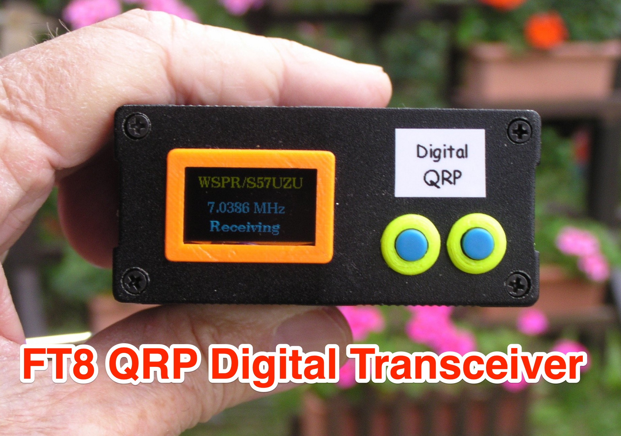 Learn how to build a QRP digital transceiver with Arduino, based on a project by Burkhard Kainka. This article covers the development process, including the source code, modifications made, and the addition of an OLED display for a more professional look. Discover the inner workings of the transceiver, from the receiver to the oscillator, and how components like the CD2003 are utilized. Explore the schematic design, the use of a PLL module Si5351A controlled by Arduino nano, and more. Ideal for hams looking to create their own digital transceiver for amateur radio operations.
 -
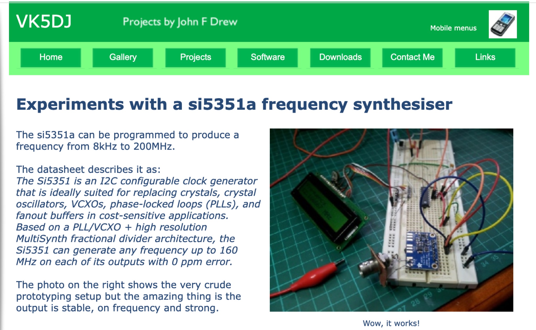 Explore VK5DJ's experiments with the si5351a frequency synthesizer, a versatile device capable of generating frequencies from 8kHz to 200MHz. Learn how this I2C configurable clock generator can replace crystals and oscillators in various applications, providing stable and precise outputs. Discover how to program the si5351a for your own signal generator projects and repeater site setups. Utilize the affordable and efficient Adafruit module for reliable performance. Enhance your understanding of PLL/VCXO architectures and fractional dividers for frequency generation. Join the PDS Forum community in experimenting with this innovative technology.