Search results
Query: power swr
Links: 91 | Categories: 3
-
 Demonstrates the construction of **magnetic loop antennas**, detailing both multi-turn and single-turn designs. It covers a 30-inch diameter multi-turn loop for 80 meters, based on a February 1996 QST article, and an octagon single-turn loop made from 15mm copper tube with a 4.8-meter circumference, operating from 7 MHz to 14 MHz. The document also presents a smaller 800mm diameter loop for 14 MHz to 28 MHz, emphasizing the importance of high-voltage tuning capacitors. Covers the design and construction of custom **butterfly capacitors** and piston capacitors, including a split stator capacitor with 140 pF capacitance and a 6000 Volt rating, and a butterfly capacitor with 5-65 pF and 7200 Volt rating. It explains why butterfly capacitors are preferred over split stator types for high power applications due to lower losses and direct series connection of rotors, reducing resistive losses from wiper contacts. Material recommendations include clear PVC for plates and brass or stainless steel for non-magnetic hardware. Addresses practical considerations such as feeding the loop with a shielded 1/5 Faraday loop made from RG213 or RG8 coax, achieving VSWR 1.1 across bands, and optimizing its placement 180° from the capacitor. It also discusses mechanical joint resistance, dissimilar metal oxidation prevention using Vaseline, and a simple method for determining radiation angle with a TL-light tube. The guide includes diagrams for rotor, stator, and end plate construction.
 -
 MFJ manufacturer of ham radio antenna products, antenna tuners, antenna analyzers, morse code & CW, SWR wattmeters, antenna accessories , power supplies, audio filters, TVI filters, baluns, coax switches and more
 -
 Base station and repeater antennas, mobile antennas, ,multi-band HF antennas , handheld transceivers, receiving and scanner antennas, power meters, swr meters, power supplies, coaxial switches
 -
 Amateur radio operators often seek reliable equipment for various modes and bands, from QRP operations to high-power DXing. Historically, Ten-Tec has been a notable manufacturer in the amateur radio market, known for its range of products including HF and VHF transceivers, RF amplifiers, and antenna analyzers. Their product line also encompassed specialized items such as QRP transceivers and kits, catering to enthusiasts of low-power communication, and antenna tuners for impedance matching. The company's offerings included test equipment vital for shack setup and maintenance, like SWR meters and RF analyzers, which assist in optimizing antenna systems and ensuring efficient power transfer. Additionally, Ten-Tec provided various accessories and components, supporting both commercial products and homebrew projects. The brand was recognized for its _made in the USA_ manufacturing, appealing to operators who prioritize domestic production. While the website currently displays limited product information, it mentions upcoming items like the _MODEL 594 PHOENIX_ and the _Tune-A-Tenna_, indicating potential future product releases.
 -
 Zetagi CB amplifiers, 10m amplifiers and accessories, power supplies, microphones, SWR and power meters, battery charges manufacturers based in Italy. - Company out of business since 2024.
 -
 Optimizing the impedance transformation and common-mode current suppression in antenna systems often involves selecting an appropriate balun. This project presents a **hybrid balun** design, combining characteristics of both voltage and current baluns to achieve superior performance, particularly when used with an antenna tuner. The design addresses issues like **common-mode current** on the feedline, which can distort the antenna's radiation pattern and introduce RFI in the shack. The construction details include winding techniques for the toroid core, component selection, and practical considerations for integration into an existing antenna system. Performance comparisons are drawn against conventional balun types, highlighting the hybrid balun's effectiveness across the HF bands. The resource provides insights into the current distribution and impedance matching properties, crucial for efficient power transfer and reduced SWR.
 -
 Determining the actual need for an antenna tuner often hinges on the specific antenna and feed line configuration in use. While many hams believe a tuner is always essential, its primary role is to present a 50-ohm impedance to the transceiver, not to "tune" the antenna itself. For instance, a resonant dipole fed with _coaxial cable_ at its design frequency typically requires no tuner, as the feed line impedance closely matches the radio's output. However, operating a non-resonant antenna, or using a resonant antenna on multiple bands, frequently necessitates a tuner to manage high Standing Wave Ratio (SWR) on the feed line. The article clarifies that a tuner placed at the transceiver only matches the radio to the feed line, not the antenna to the feed line. For maximum efficiency with a non-resonant antenna, an _automatic antenna tuner_ (ATU) or a remote tuner placed at the antenna feed point is often more effective, minimizing losses in the feed line. The discussion also touches on the practical implications of SWR, noting that modern transceivers often fold back power at high SWR, making a tuner a practical necessity to achieve full output power, even if the antenna itself is not perfectly matched.
 -
 The project details a DIY SWR/Wattmeter designed around an _Arduino Uno_ shield, providing capabilities to measure RF power from 2 to **200 watts** and Standing Wave Ratio (SWR) for HF amateur radio bands. This construction features a compact design, integrating the measurement circuitry directly onto a custom PCB that interfaces with the Arduino Uno microcontroller. Key components include a directional coupler for sensing forward and reflected power, precision rectifiers, and analog-to-digital conversion for processing RF signals. The Arduino firmware handles calibration, calculations, and displays the results on an integrated LCD, offering real-time feedback on antenna system performance. The design prioritizes simplicity for homebrewers. Performance specifications indicate accurate readings within the **2-200W** power range, suitable for typical QRP to medium-power HF operations. The project provides schematics and a basic overview of the software logic.
 -
 NGC is now distributor for COMET and MALDOL brand antenna products designed, manufactured in Japan. Distributor of DAIWA brand RF SWR/power meters and switching power supplies, antennas, test equipment, antenna analyzers and more
 -
 Demonstrates the construction of a **remote antenna tuner** utilizing a standard radio-controlled (RC) servo mechanism to adjust a variable capacitor. The design focuses on enabling remote tuning for narrow-bandwidth antennas, specifically mentioning frame and packing crate antennas, from within the shack. It covers the mechanical arrangement for integrating the servo with a capacitor and provides a circuit diagram for a control unit that generates the necessary 0.5mS to 1.5mS pulse-width modulation (PWM) signals to drive the servo's 180-degree rotation. This setup was successfully tested with up to 20 watts RF power without arcing or adverse effects on the servo, though tuning was performed at 1 watt for VSWR readings. The resource highlights the use of inexpensive, readily available components, such as Futaba servos, and details critical considerations like power supply decoupling with a 47uF capacitor to prevent unintended servo movement upon power-off. The system provides a practical solution for optimizing antenna performance for specific frequencies without manual adjustment at the antenna itself.
 -
 Maco Manufacturing, HF Antennas, gamma matches, cable assemblies, power supply, swr meters, watt meters
 -
 The 80-meter loop antenna, measuring 86 meters (282 feet) of wire, effectively operates across 8 HF bands from 80 through 10 meters, despite its length being a compromise for specific bands. This design prioritizes a "low enough" SWR across multiple bands, aiming for lower SWR values on higher frequencies due to increased feedline losses. A 200-ohm feedpoint impedance provides a workable SWR on every band, with feedpoint impedances ranging from 100 ohms for lower bands to 300 ohms for higher bands. Radiation patterns for the 80-meter loop, mounted at 15 meters high, show a maximum gain of 7.6 dBi at a 90-degree takeoff angle on 80 meters, and up to 12.9 dBi at a 10-degree takeoff angle on 12 meters. This configuration supports regional contacts on 80 meters and provides good DX performance on higher bands. Practical construction notes emphasize using robust supports like trees, ensuring wire slack with _egg insulators_ for wind resilience, and employing an oversized 2 kW 4:1 _balun_ to safely handle higher SWR conditions, even with 100W transceivers. Feedline losses are minimized using _LMR-400_ coax or ladder line, with power transfer efficiency between 80% and 95%. Antenna simulations were performed using _xnec2c_, and the provided NEC file is compatible with other NEC2 derivatives. The antenna is tunable on 6 of 8 bands with an internal ATU and all 8 bands with an external autotuner like the LDG AT-200 Pro.
 -
 This sketch will read RF power and SWR from any SWR bridge, designed to work on VHF UHF bands
 -
 Presents a catalog of **QRP** transceivers, antenna tuners, and related accessories for amateur radio operators. The product line includes the ZM-2 antenna tuner, designed for efficient impedance matching across HF bands, and the NW-series QRP transceivers, offering low-power CW operation. Additionally, the site details various ladder line insulators and specialized connectors, emphasizing robust construction for field deployment and home station use. Each product listing provides specifications, operational parameters, and pricing information. Compares the features of different **QRP transceiver** models, such as the NW-40 and NW-20, highlighting their respective band coverage and power output capabilities. The ZM-2 tuner's performance is detailed with typical SWR reduction figures for various antenna types, demonstrating its utility for portable and fixed stations. Customer testimonials and product images illustrate the practical application and build quality of EMTECH's offerings, providing insights into their durability and ease of integration into existing amateur radio setups.
 -
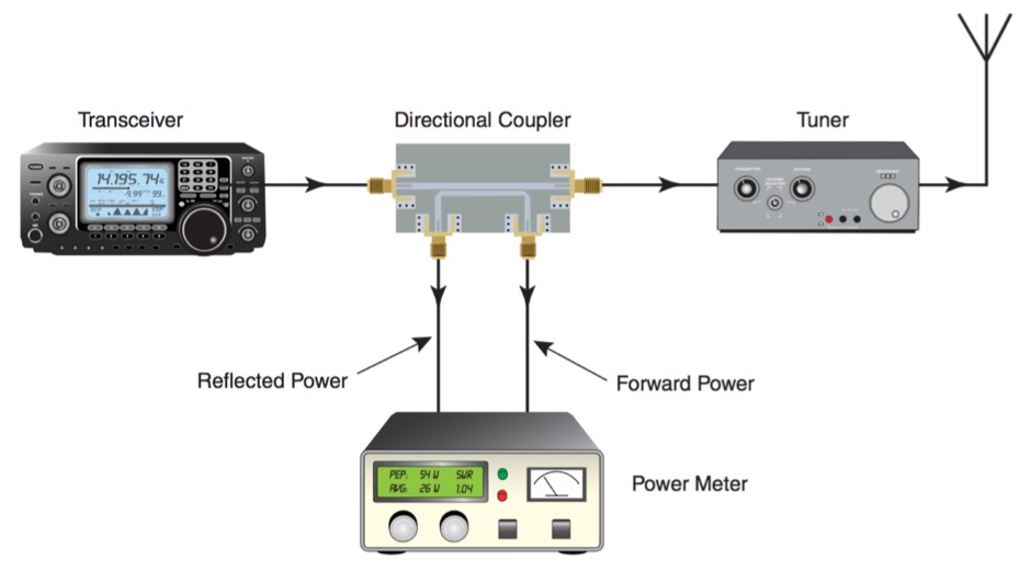
 We worry a lot about Standing Wave Ratio (SWR) in amateur radio since SWR is one indication of how well our antenna system is working. Most HF transceivers and antenna tuners have built in SWR meters. SWR is a measure of a transceiver' s output power verses the portion of that power reflected by the antenna system
 -
 Presents a crystal-controlled CW transmitter design for the 40-meter band, delivering 5 to 7.5 watts output power. The circuit innovatively employs an _IRF510_ power MOSFET in the final amplifier stage, diverging from conventional bipolar transistors. This design offers high gain, nearly 90% efficiency, and robust resistance to high SWR, allowing 30-second key-down operation into an open circuit without damage. A critical aspect is the precise adjustment of the MOSFET gate bias via a 10K trimmer pot, _R10_, to maintain quiescent current between 5 and 10 mA, preventing thermal runaway inherent to bipolar devices. The prototype was constructed on a _Radio Shack universal board_ and achieved immediate operational success. The design requires a 15-volt Zener diode to protect the MOSFET gate from overvoltage. Component sourcing information is provided, including specific crystal frequencies (7.040 MHz or 7.122 MHz) available from _Dan’s Small Parts & Kits_ or Doug Hendricks. The fixed frequency can be slightly adjusted with a trimmer capacitor. A complete bill of materials, including resistor values, capacitor types, toroid specifications, and transistor part numbers, is detailed, alongside a clear schematic diagram.
 -
 This homebrewed antenna tuning unit also incorporates a 50-ohm QRP dummy load, power meter (1 or 10 Watts full scale), and SWR meter
 -
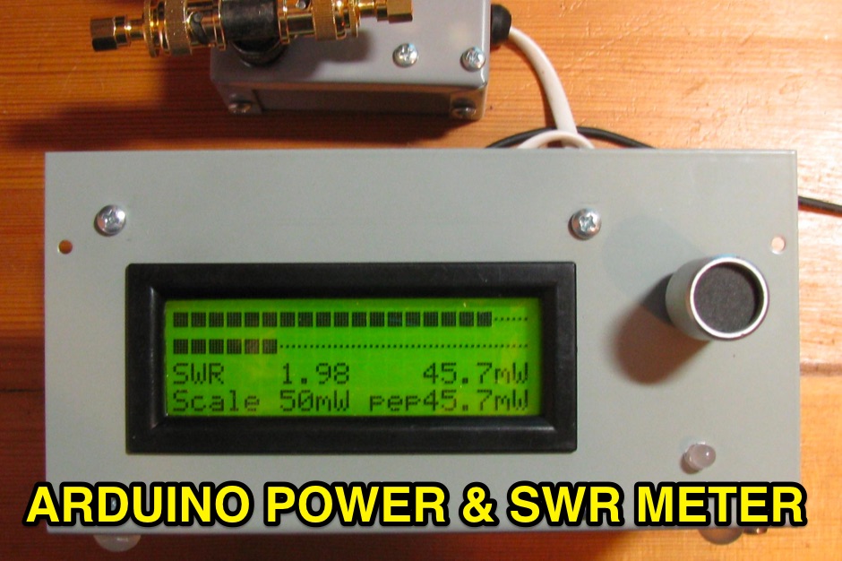 Power and SWR Meter with dual bargraphs and sticky bar, using 2x AD8307
 -
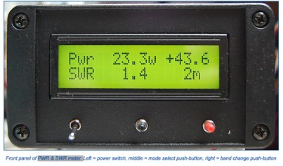
 A KD1JV Melt solder kit, a swr and power meter operating from 160 to 6 meters ideal for portable and field use
 -
 AEA Technology Inc. is a pioneer and leading manufacturer of RF and cable test equipment for the wireless, Telco, CATV, NMR & MRI, RFID, telemetry, aviation, commercial, military, and two-way radio industries. Produces SWR Meters, Pre Amplifiers, filters, power meters and antenna testing products
 -
 Constructing a **2-meter** J-pole antenna from readily available copper plumbing components offers a robust and cost-effective solution for VHF operation. This design, dubbed the "Plumber's Delight," functions essentially as a half-wave dipole fed by 50-ohm coax via a **gamma match**. It incorporates a quarter-wave copper tubing support, which, when affixed to a metal mast or tower, enhances forward power in the direction of the radiating elements. The original configuration utilized a small ceramic trimmer capacitor for the gamma match, suitable for up to 10 watts. A subsequent modification replaced this with a 50 pF variable capacitor housed in a plastic enclosure, accommodating higher RF power and improving weather resistance. The antenna elements are secured using a copper "T" fitting, and an SO-239 connector mounts directly to this fitting. Performance includes gain away from the support mast, and tuning is straightforward by adjusting the gamma match capacitor for a 1:1 SWR. The total cost for materials, excluding the capacitor and coax, can be under $10.
 -
 SWR and RF power meter for home usage, 8 different RF probes with different characteristics and power ranges by OK1DX
 -
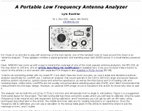 A Portable Low Frequency Antenna Analyzer, For those of us who like to play with antennas on the ham bands, one of the handiest tools to have around the shack is an "antenna analyzer". These gadgets combine a signal generator and standing-wave ratio (SWR) sensor in a small battery-powered unit.
 -
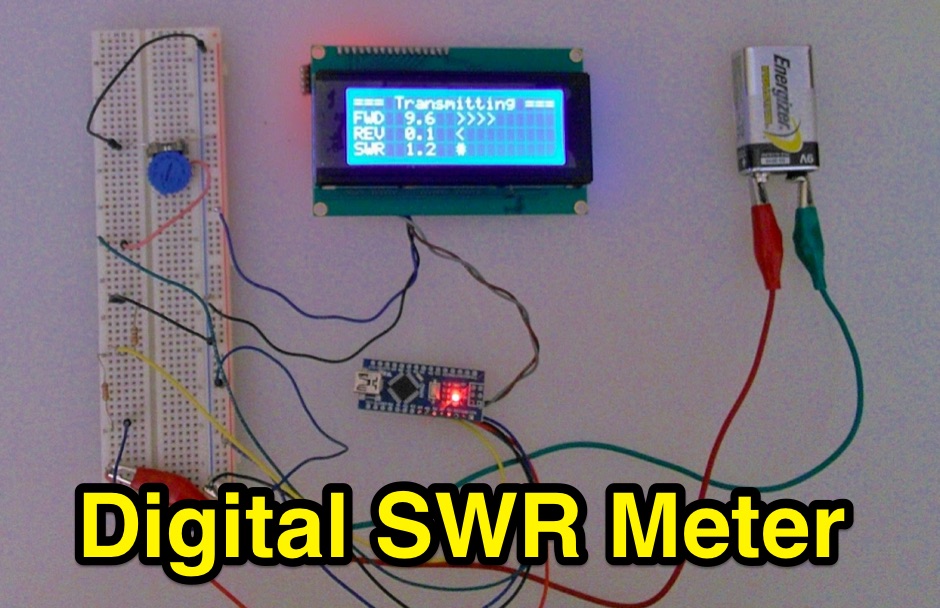 Inline RF Power & VSWR Meter. A DIY meter 0 to 30 Watt with Average and Peak. Circuit Description, Arduino Nano software code and part list to DIY your own Digital SWR Meter
 -
 Over 75 years of engineering expertise underpins Bird Electronic's offerings in RF power measurement, critical for maintaining peak performance in amateur radio stations and professional communication systems. The company specializes in a range of test equipment, including wattmeters, SWR meters, and antenna analyzers, essential for optimizing antenna systems and ensuring efficient power transfer. Their product line extends to various RF components such as filters, cables, and connectors, all designed to meet stringent technical specifications for reliability and accuracy across diverse frequency bands. Bird Electronic's instruments, like the _Bird 43_ Thruline Wattmeter, are widely recognized for their robust construction and precise measurement capabilities, providing hams with confidence in their station's operational parameters. These tools enable accurate assessment of forward and reflected power, SWR, and modulation characteristics, which are vital for troubleshooting and maximizing radiated power. The company's commitment to innovation ensures that its products remain relevant for modern RF challenges, from HF through microwave applications, supporting both traditional analog and advanced digital modes.
 -
 Details a practical QRP wattmeter construction, leveraging a simplified SWR meter design by JA6HIC. The project focuses on a forward-only power measurement circuit, providing a functional instrument for RF power levels from milliwatts up to 5 watts. It maintains a 50-ohm input and output impedance, suitable for typical QRP transceivers and antenna systems. The resource includes the schematic for the "VSW" (Very Simple Wattmeter) and outlines a six-step alignment procedure. This calibration process involves using a known RF source up to 5W, setting full-scale deflection, and marking power increments. It also addresses minimizing frequency effects on readings with a 100pF trimmer capacitor, noting that measurement error is highest at the lower end of the scale. Construction notes mention using a piece of RG-213 coaxial cable for the inductance and coupler, with the wattmeter assembled in early 2003. The author provides an example measurement showing 0.8W into a dummy load and 1W into a 3-element beam.
 -
 Amateur radio accessories, power supplies, tvi filters, speakers, microphones, swr meters, preamplifiers, switches, cable and connectors,
 -
 Daiwa Industry, maker of power suppliers, coax cable and antenna switches, power meters, SWR meters, DC-DC converters
 -
 ERP Calculator is an Amateur Radio software utility designed to perform a side-by-side comparison of two Ham Radio antenna systems. ERP Calculator comes pre-programmed with data files including published data for several popular brands and types of coax cable as well as several popular antenna system brands and models. ERP Calculator displays values of ERP, Antenna Power Gain, Antenna Feed point Power, Antenna System Gain in dB, Antenna Gain in dBd, SWR Attenuation in dB, SWR Power Attenuation, Coax Loss in dB, and Coax Power Loss
 -
 AEA Wireless Director Software Series turns PC's (running Windows 95/98/2000/ME or NT) into powerful tools that expand the use and power of SWR, Return Loss and Complex Impedance Analyzers.
 -
 That just about sums up many peoples attitude towards test equipment. Multimeter, SWR/Power Meter, Dip Oscillator, RF Signal Generator, Cathode Ray Oscilloscope
 -

-
 Computes the Standing Wave Ratio, given the power readings on a line.
 -
 Whether we are tuning up homebrew equipment, checking antenna VSWR, adjusting a linear amplifier, or just monitoring output power during a contest, almost all aspects of ham operation can use a power meter. Paul Wade W1GHZ
 -
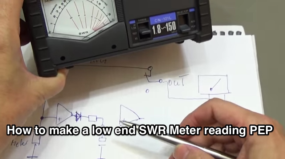 Building a PEP Power circuit for all analogue watt-meter
 -
 HAMIC, is a program designed to simplify a number of calculations commonly used by HAMs. It is designed for the HAM radio hobbyist, but may be useful to others as well. HAMIC has a simple to use, but powerful graphical interface that allows solving simple circuits such as resistors in series or parallel, or more complex circuits such as L networks or T networks. As well, other calculations such as SWR and reactance conversions are supported. Windows shareware.
 -
 The circuit is based on two AD8307 log amplifiers, which are connected to the forward and reflected ports on a directional coupler
 -
 Every ham needs an RF power meter. Here is a high performance unit to build at home.
 -
 SWR (standing wave ratio), is a measurement of how efficiently your antenna system will radiate the power available from your radio. In simple terms, your radio would like to radiate all of its power, but can only do so if the other components cooperate
 -
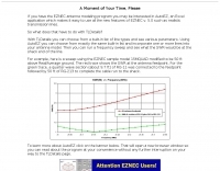 Transmission Line Details. This utility program shows the impedance and SWR at both ends of a transmission line and the details of power loss in the line. It includes characteristics for over 40 built-in line types. You can modify these values to see how small changes affect the results or to specify custom lines. All program inputs may be changed directly or you can use spin buttons to make the changes. If you are using a moderately fast computer you can hold down a spinner and "watch the movie" on the charts as the results are recomputed. By AC6LA
 -
 A fractional bandwidth of up to 30:1 characterizes spiral antennas, making them highly effective across a very wide frequency range, often from 1 GHz to 30 GHz. The resource details two primary types: the **Log-Periodic Spiral Antenna** and the **Archimedean Spiral Antenna**, defining each with specific polar functions and illustrating their planar configurations. It explains that spiral antennas are typically circularly polarized, with a Half-Power Beamwidth (HPBW) of approximately 70-90 degrees, and a peak radiation direction perpendicular to the spiral plane. The content elaborates on critical design parameters affecting radiation, including the total length (outer radius) for lowest frequency, the flare rate ('a' constant) for optimal radiation versus capacitive behavior, the feed structure (often an infinite balun) for high-frequency operation, and the number of turns (typically 1.5 to 3 turns). It also discusses the theoretical impedance of 188 Ohms for Log-Periodic spirals, derived from Babinet's Principle, noting actual impedances are often 100-150 Ohms. The article presents a simple construction method for an Archimedean spiral, demonstrating VSWR and efficiency measurements. Measurements from a constructed spiral antenna show a VSWR that is fairly constant across the band, albeit with a mismatch loss of about 3 dB. The antenna efficiency remains around -5 dB (31.6%) across its operating range, indicating a decent wideband radiator despite opportunities for optimization.
 -
 This document details the design and construction of the PA70H, a 50-watt RF amplifier for the 70MHz (4-meter) amateur radio band. Built around the Mitsubishi RD70HVF1 MOSFET transistor, the amplifier delivers 45-55W output with 3-5W input power while operating on 13.8V DC at approximately 7-8A. The PCB design incorporates multiple protection circuits including overcurrent, SWR, and temperature control. The amplifier features various control modes including GND PTT, +13.8V PTT, and RF VOX. Two versions are available: PA70HLI (requiring 100mW input with additional driver) and PA70H (for 3-5W input). The comprehensive documentation includes circuit diagrams, assembly instructions, and performance data showing successful operation from both 100mW and 3.5W input sources.
 -
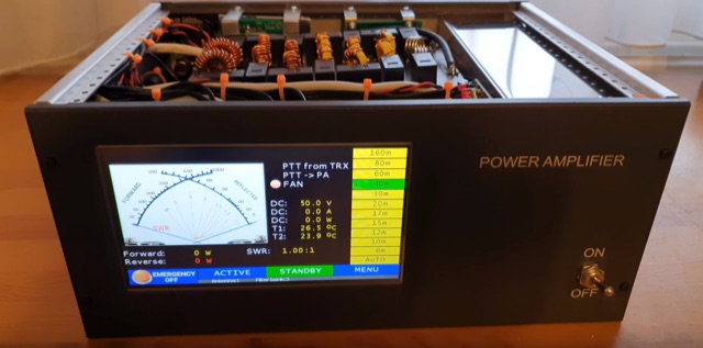 A comeplete home made 600W LDMOS RF power amplifier. Settings can be made on a 7-inch touch screen, and on this screen you can see a lot of useful information during operation, such as output power, temperature, SWR, and so on. The power amplifier includes 2 MRF300 LDMOS FETs and several built-in sensors. The amplifier also contains several types of protection functions like too high current, too high swr, too high temperature, etc.
 -
 A 50-ohm generator feeding a 50-ohm line connected to a _quarter-wave transformer_ (150 ohms) terminated in a 450-ohm load is analyzed to understand transient behavior. The paper meticulously tracks voltage and current waves, reflection coefficients, and power levels through a sequence of events, starting from quiescent conditions. It details how incident and reflected waves combine and interact at impedance discontinuities, illustrating the dynamic changes in impedance and SWR at various points in the system. The analysis reveals that the impedance at the interface between the 50-ohm line and the 150-ohm transformer changes from 150 ohms to **64.3 ohms** after the first reflected wave arrives. Subsequent reflections cause the impedance to asymptotically approach 50 ohms, reaching **53.22 ohms** after five wave terms. The study also examines the generator's reaction to transient SWR changes, noting that a 3:1 SWR can temporarily reduce generator output to 0.75 watts, but these effects are temporary and diminish as the system approaches steady-state conditions.
 -
 Chart showing how SWR effects how much power you actually radiate from your antenna.
 -
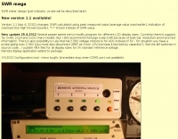
 A system designed to automatically tune small transmitting magnetic loop antennas, particularly beneficial for **contest operations** where rapid frequency changes are common. The core of the system involves a PC-based control application, AutoCap, written in C#, which monitors antenna SWR via an external meter and commands a motor interface to adjust the loop's variable capacitor. The software is compatible with Windows and Linux via the Mono framework, offering a graphical user interface for monitoring system status, SWR, power, and motor commands. Key components include one or more magnetic loop antennas equipped with DC or stepper motors for capacitor adjustment, an SWR meter with data output (such as the Telepost LP-100A or a homebrew serial/USB SWR meter), the AutoCap PC software, and a motor interface. The most effective motor interface utilizes an **Arduino-based controller** with custom firmware, providing precise control over both simple DC motors and stepper motors, and supporting features like motor braking for finer adjustments. The system allows for configurable SWR thresholds, pulse widths, and motor effort settings to optimize tuning speed and resolution. Optional radio integration provides frequency hints, enabling the algorithm to learn the relationship between motor actions and resonant frequency, thereby speeding up initial tuning responses. The software also supports antenna profiles, allowing operators to save and recall specific configurations for different loops, including accumulated frequency hint data.
 -
 DK7ZB's fan dipole designs address the challenge of operating multiple HF bands with a single feedline, providing practical construction details for **multiband wire antennas**. The resource outlines specific lengths for half-dipoles across various band combinations, including 10-15-20m for classic bands and 12-17-30m for WARC bands. It emphasizes the importance of proper spacing between resonant elements to avoid impedance interaction and high SWR, a common issue when frequencies are too close. The article details the use of **current baluns** built with FT240-43 or FT140-43 cores, specifying turns and cable types for 1KW and 400-Watt power levels. It includes a correction table for adjusting dipole lengths based on frequency shifts, aiding in fine-tuning resonance. The 20+40m dipole is noted for its ability to operate on 15m with an ATU, demonstrating versatility.
 -
 The WaveNode WN-1 is a precision, full-featured Amateur Radio Station Monitoring System which now includes Audio Announcing for RF power, SWR, and DC monitoring using HF and UHF remote sensors.
 -
 Presents the construction of a 2-meter **Skeleton Slot Yagi** stack, detailing the design process and practical considerations for VHF operation. The author shares insights from building and testing this antenna, emphasizing its performance characteristics for local and extended range contacts. The project outlines the specific dimensions and materials used, providing a clear path for other radio amateurs to replicate or adapt the design for their own stations. The resource covers the unique aspects of the Skeleton Slot radiator, explaining how its geometry contributes to gain and pattern control. It includes discussions on impedance matching and feedline considerations crucial for optimizing power transfer and minimizing SWR. The article draws on real-world testing, offering practical results that validate the theoretical design. This project serves as a valuable reference for those interested in custom VHF antenna solutions.
 -
 The **Solarcon A99** vertical antenna, a half-wave over a quarter-wave variable mutual inductance design, primarily serves the 11-meter CB band but also finds use on 10 and 12 meters for amateur radio operators. Its simple construction, consisting of three fiberglass sections and a 16 AWG radiating element, makes it an accessible option for new operators or those seeking an easy-to-install base station antenna without complex mounting requirements. Despite claims of 9.9 dBi gain being widely considered exaggerated, and a manufacturer rating of 2000 watts power handling often viewed with skepticism (with 300 watts suggested as a practical limit), the A99 maintains popularity due to its low cost and ease of deployment. It typically tunes to a 1.2-1.3 SWR out of the box, requiring minimal adjustment via its two tuning rings. Its high angle of radiation allows for effective local communication even when mounted at low heights, such as 8-10 feet off the ground. However, the A99 is known for significant RF bleed-over issues, particularly when operated with higher power or mounted close to residential electronics. While its internal design is often described as cheap, the antenna exhibits remarkable durability, frequently lasting a decade or more in various weather conditions. Its affordability and straightforward setup continue to make it a go-to choice for many radio enthusiasts.