Search results
Query: 70 cm antenna
Links: 91 | Categories: 1
Categories
-
 Design your VHF UHF Yagi antenna online, a JavaScript enhanced web page that implements the design of an antenna for 2m and 70cm bands. This page offers a streamlined experience for Yagi antenna design enthusiasts. It assumes prior knowledge of Yagi design principles, minimizing distractions with a user-friendly interface. Equipped with essential equations, it provides instant design feedback. Red font warnings indicate design limitations, ensuring practical results. Constraints include Gain (11.8-21.6 dBd) and Boom Length (2.2-39 wavelengths), with additional frequency-dependent restrictions noted in input fields.
 -
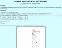
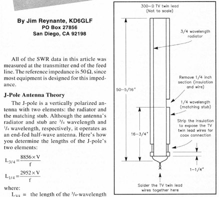 An Easy Dual-Band VHF/UHF vertical Antenna made with a TV twin lead and coax cable
 -

-
 How to Build a Dual-Band Antenna for 2M/70cm presentation PDF file
 -
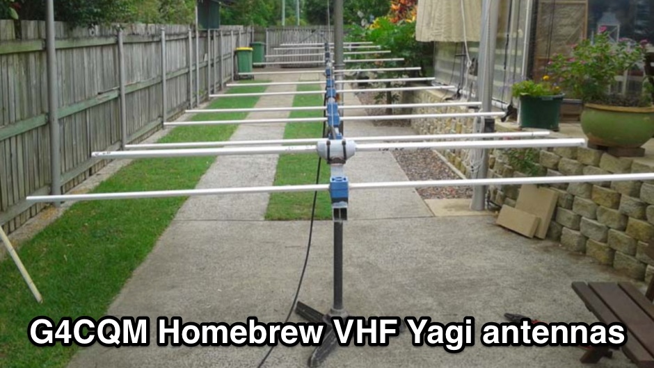 Homebrew VHF Yagi 50MHz 144MHz 432MHz 1296MHz 2320MHz 6M 2M 70CM 23CM 13CM Yagis
 -
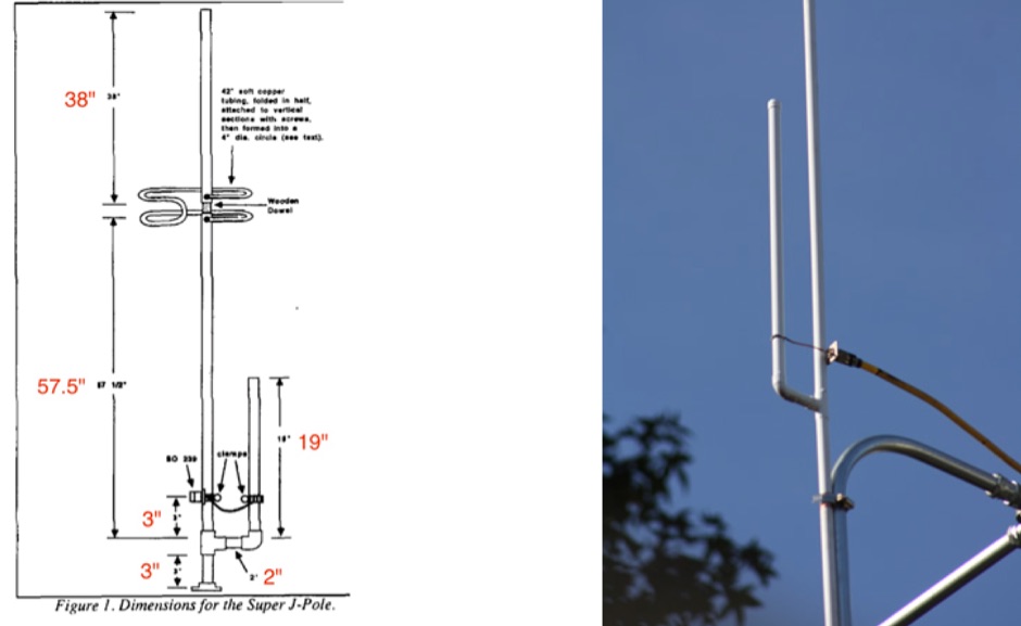
 Here is a 70cm (440 Mhz) J-Pole antenna that is inexpensive, and easy to build. Author use 1/2 inch copper pipe, and the associated fittings necessary. The dimensions aren't typical however, this is what it took to get its SWR low.
 -
-
 The Flower Pot Antenna project details a portable dual-band antenna primarily operating on 10 meters, with secondary resonance near the 30-meter band. Construction involves winding RG58 coaxial cable uniformly around a large plastic flower pot, approximately 70cm high with a 60cm top diameter. The design eliminates the need for radials, contributing to its compact and lightweight nature. Key construction steps include soldering the inner conductor to the shield at one end of the wound cable and connecting the wound cable's shield to the rig cable's inner conductor at the base. An LC network, comprising a variable capacitor (0-200pF) and an inductor (10 coils, 5cm diameter, 2mm wire), is inserted between the wound cable's inner conductor and the rig cable's shield. Tuning is performed with an antenna analyzer, adjusting cable length and the variable capacitor for optimal impedance on 10 meters. The antenna performs effectively when installed horizontally.
 -
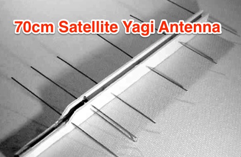
 Here is a high-performance hand-held beam antenna that is easy to build and guaranteed to improve your downlink from the LEO satellites over ANY rubber duck or mobile whip
 -
 Members discuss the operation of and modifications to this outstanding QRP rig that covers 160m 70cm with all modes. Site contains a large database of FT-817 FAQs and data files. Antennas, tuners, and power sources are also covered as related to this ultra-compact transceiver.
 -
 Build your own antenna for the 23cm band ( 1250Mhz - 1280Mc ) using some aluminium and this simple design.
 -
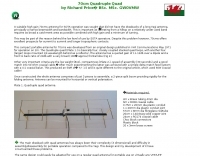
 A suitable high gain 70cms antenna for SOTA operation by Richard Price GW0VMW
 -
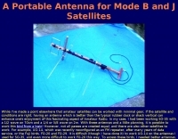 A portable antenna for mode B and J satellites
 -
 Homebrew a j-pole 2mt and 70 cm antenna project. Make it cheap. This article includes homebrewing instructions, parts lists, tools needed and printable documentation.
 -
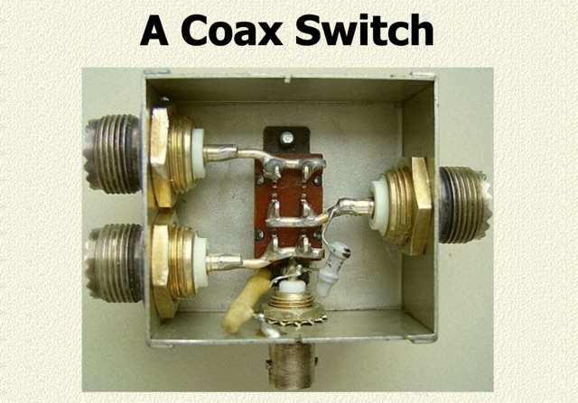 An inexpensive coax switch. shows a proven inexpensive home-made antenna selection switch. If you question the use of a cheap slide switch and SO239 coax sockets, read on. Measurements in a physics lab showed there to be practically no reflection on HF and even on 70 cm the SWR was below 1.3 : 1
 -
 The 30/40 meter **vertical antenna** project by IK4DCS details the construction of a shortened, self-supporting design, reaching a total length of 5 meters. The antenna incorporates a linear loading section and a coaxial cable trap for 30 meters, based on the "Antenne Volume 2°" text by Nerio Neri (page 223). The design uses six radials, three for each band, positioned at approximately 90° inclination and at least one meter above the roof or ground, connected via a 1:1 balun at the feed point. Mechanical construction utilizes aluminum tubing, with a 2.30-meter primary radiator section (30 mm diameter) joined to a second part using a Teflon insert and a PVC sleeve for rigidity. The linear load, approximately 3.70 meters long, accounts for a 30% physical shortening of the quarter-wave element. A capacitive load, made from three 50 cm radials, is integrated into the 40-meter top section for fine-tuning. Final adjustments involved radial inclination for 40 meters, as initial testing showed increased SWR and interference on 30 meters due to nearby resonant structures. The author emphasizes the importance of clear space for optimal performance and provides drawings and photos to clarify the build process.
 -
-
 An AO-10 antenna by K5OE, this design is optimized for 436.8 mHz with a 50 Ohm feed
 -

-
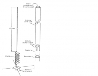
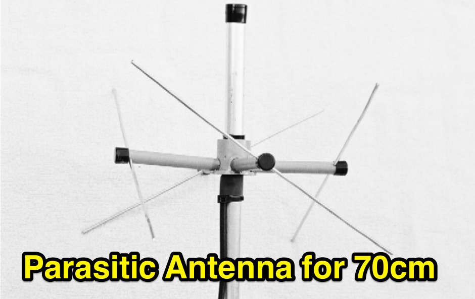 A Parasitic Lindenblad Antenna for 70cm by Anthony Monteiro, AA2TX. This is the official 16 pages PDF File published by AMSAT about the 70cm Parasitic Lindenblad Antenna.
 -
-
-
-

-
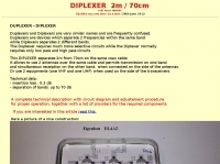 This DIPLEXER separates 2m from 70cm on the same coax cable, and allows to use 2 antennas over the same cable and permits transmission on one band and simultaneous receiption on the other band by hb9abx
 -
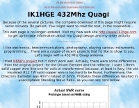 Quagi 8el 70cm improved 13.77dBi by IK1HGE
 -
-
 A suitable high gain 70cms antenna for SOTA operation was sought that did not have the drawbacks of a long Yagi antenna, principally a narrow beamwidth and bandwidth.
 -
-
-
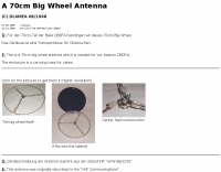 This is a 70cm big wheel antenna which is used at DB0FAI beacon
 -
 Constructing a compact, two-band magnetic loop antenna for HF operation, especially from constrained locations like a balcony, presents unique challenges. OK1FOU's design, inspired by DJ3RW's 50 MHz loop, addresses these by employing an unusual side-fed configuration and placing the symmetric, two-section variable tuning capacitor at the bottom of the loop, directly connected to the coax shield. The article provides specific material recommendations, including two 1-meter wooden pales and about 3 meters of thick loudspeaker cable, noting the high current (60A at 100W) in the loop. Construction steps detail forming two turns with a 5 cm gap, using a GDO to pre-tune the open loop to a frequency slightly above the desired highest band, and then integrating the tuning and coupling capacitors. For 10/14 MHz, an open loop resonance of 16-17 MHz is suggested. Practical experience with the 10 MHz band from a third-floor balcony in Prague (JO70GC) shows a 1:1 SWR across most of the band without an external ATU. While DX traffic was modest due to the urban environment, QSO examples with RA6WF, LA6GIA, G0NXA, and LZ1QK on 10 MHz are provided, demonstrating its operational capability.
 -
 Antenna was designed for SO-50 satellite operation but can be used for any VHF/UHF activity. It's a mix of a Moxon Antenna and a Yagi antenna. It has gains 4 dBd on 2m and 6.5 dBd on 70cm bands and it is fed via single 50 Ohm cable.
 -
-

-
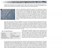
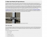
 Demonstrates the design and construction of a 9-element Yagi antenna for the **70 cm band** (432 MHz), based on the DK7ZB concept. The resource details EZNEC+ calculations for a single antenna, providing gain, sidelobe suppression, and front-to-back ratio figures. It also presents a comprehensive analysis of stacking two such antennas, including optimal stacking distance (1000 mm) and the resulting performance enhancements for the stacked array, such as an increased gain of 17.03 dBi. The article includes detailed drawings, wire file dimensions in millimeters, and azimuth/elevation plots for both single and stacked configurations. Practical construction steps are documented with original photographs, illustrating element mounting, the **28 Ohm matching system** using two quarter-wave 75 Ohm transmission lines, and the critical N-connector wiring. It also covers the iterative process of fine-tuning the driven element length to achieve a return loss of 20 dB, validating the EZNEC+ simulation results with actual measurements.
 -
 The antenna is a vertical dipole, around which four parasitic elements are forming a circle.
 -
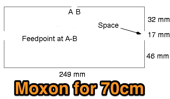 A moxon antenna project for 70 cm band, test and results of this popular antenna model applies to UHF bands.
 -

-
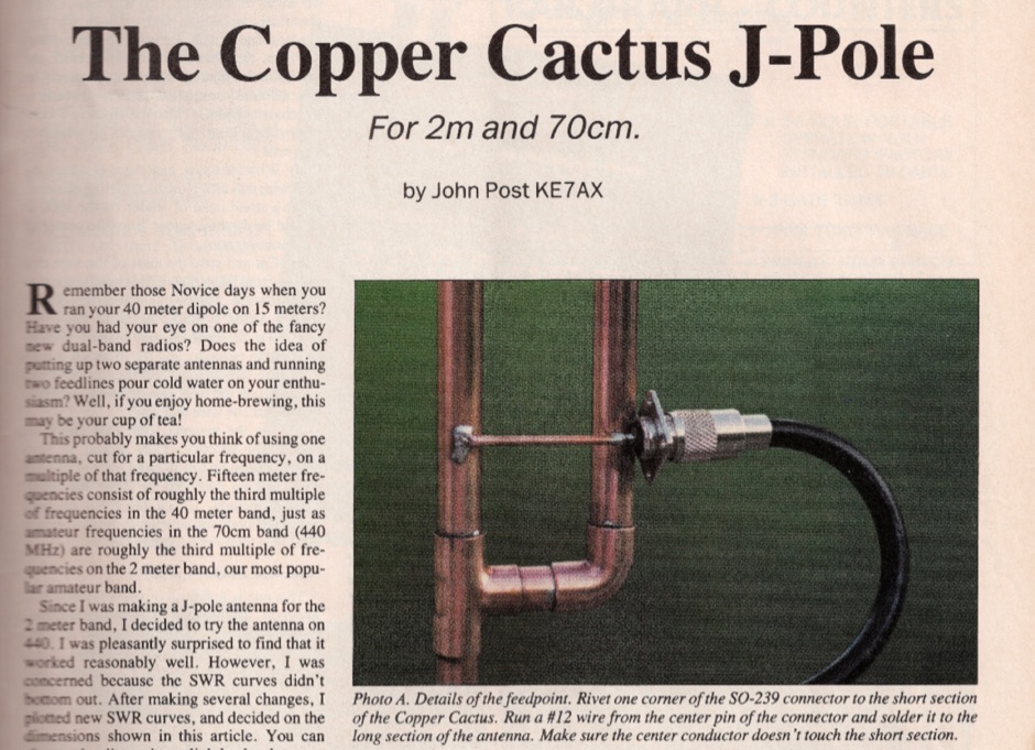 Original article published on February 1992 on 73 Amateur Radio Today about the 2m and 70 cm copper cactus J-pole antenna
 -

-
 On this page is the design for Dual Band 2M / 70cm antenna with 3.2mm elements. The antenna has a 50 ohm designed driver. This Yagi has a unique element called a Open Sleeve
 -
 Building an omnidirectionnal antenna for the 23 cm band, 1240 - 1270 Mhz
 -
-
 A vertical monoband antenna design that can work from 6 meters to 70 cm by F5ZV in French
 -
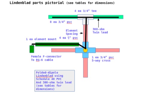 This document contains the detailed instructions to build a homemade lindenblad antenna using a twin-lead as dipole elements. This document contains 9 pages and includes a detailed construction sequence and some drawings to build this antenna for UHF and VHF ham radio bands
 -
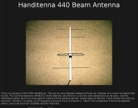 A 4 elements handitenna for 70 cm band. This is my version of the K5OE Handitenna. This one is a four Element instead of three, as I had less of a crunch on space than he did. The 1st three elements (Reflector, Driven Element, and Director 1) are the same dimensions as his were.
 -
 A 70cm and 2m 6 elements yagi antenna plan based on the IEEE Transactions on Antennas and Propagation
 -
-
 US Antenna manufacturer offering base and mobile antennas for 2 meter, 1.25 meter and 70 cm Amateur Radio GMRS and MURS Citizens Band Radio VHF and UHF Business Band Radio HF, VHF and UHF Scanning