Search results
Query: 11 meters
Links: 60 | Categories: 0
-
 With this antenna the coverage is 80,40,20,15 and 10 meter band without any antenna tuner and the average SWR is below 1.2 on phone bands. The total antenna lenght is about 23 meters , with one 20.4 meters long segment from the 1:49 transformer to the 110uh coil and about 2.2 meters long segment from the coil to the insulator.
 -
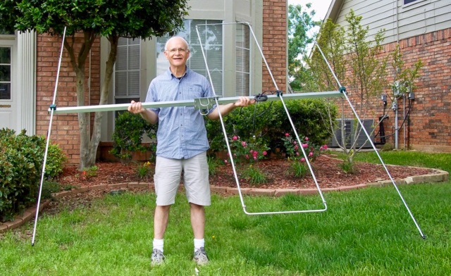 Getting Started on the Magic Band is a very exaustive article about operating the six meters band. It covers several aspects of operations, techniques, tips and guidelines on getting started on the six meters band.
 -
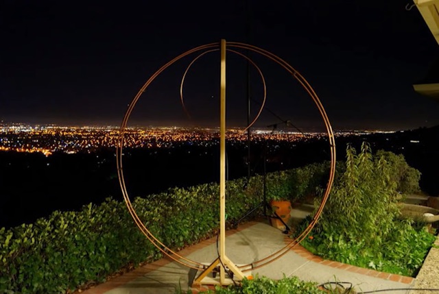 Jeri Ellsworthhas started a video series devoted to building a magnetic loop antenna for the 160- and 80-meter bands. The first video, included after the break, is an overview of the rationale behind a magnetic loop
 -
 DL7JV shares his practical experience building and testing capacitive antennas, initially skeptical of their performance compared to magnetic loops and mono-band dipoles. His interest was piqued after hearing a Spanish station running 100 Watts on 80 meters with a 1-meter Micro Vert, making DX contacts into PY and UA0, despite the antenna being only 4 meters high in a garden. This prompted DL7JV to investigate further, consulting resources from DL7PE and DL7AHW, the latter providing DOS programs like "Mitspule.exe" and "Spulenprg.zip" for calculating antenna dimensions and coil conversions. The article outlines the construction of two prototype antennas: one for 7.050 MHz using a 75mm PVC pipe and another for 3.550 MHz with a 110mm PVC pipe. Both designs feature aluminum foil condensers and coils wound from 1mm² H07V-K wire. DL7JV provides specific measurements for the condenser capacitance, surface area, diameter, height, coil inductance, turns, and wire length for both 40m and 80m versions, along with RG58 feedline lengths. Initial reception tests for the 7 MHz antenna, placed indoors, yielded impressive S9+5 signals from a German station compared to an S8 from a 42-meter roof-mounted loop, even hearing a Japanese station. Transmission attempts on April 4, 2004, despite moderate solar storm conditions, resulted in successful QSOs on 7 MHz with EA5OT (579/559) and on 3.5 MHz with YT1NT (579/559) and G4KKI (579/559) using 100 Watts. DL7JV notes the antenna's sensitivity to coordination and feedline layout, suggesting a modification from DL7AXO involving a 500pF fixed capacitor and coil tap for improved SWR stability. He concludes that while the capacitive antenna is space-saving and performs well for reception and 100W transmission indoors, its transmit performance doesn't yet match larger antennas, with further outdoor field tests planned. DL7JV also intends to build a 1.8 MHz version.
 -
 The DK7ZB-Dualband-Moxon-Beam provides a compact, high-performance antenna solution for 28 MHz and 50 MHz operations, utilizing a single 50-ohm feedpoint. This design functions as a mini-beam on 10 meters, achieving a gain of **4.0 dBd** with a front-to-back ratio of _30 dB_, while operating as a 2-element Yagi on 6 meters, yielding a gain of **4.3 dBd** and an 11 dB F/B ratio. The antenna's dimensions are approximately two-thirds that of a full-size 10-meter beam, making it suitable for smaller spaces. Construction details include a parts list specifying aluminum tubes of various diameters and lengths for the reflector and radiator elements. Builders like Aleks (S54S) and Marcio (PY2OK) have successfully replicated the design, with Aleks noting the utility of bending corners during assembly. Fine-tuning is accomplished by adjusting the length of specific elements that slide into larger tubes. The feeding system incorporates a balun, with options for either 300 watts using RG188 on an FT140-43 core or 1 kilowatt using _Aircell-5_ on an FT240-43 core, ensuring versatility for different power levels.
 -
 The Portable EFHW antenna for the 40, 20, 15, and 10-meter bands utilizes a broadband transformer with a 1:49 ratio, designed on a PCB by either Jan or DL2MAN. The design incorporates an **FT114 core**, offering an alternative to the FT82 core. The antenna requires precisely 20.5 meters of DX Wire Ultralight for optimal performance. Additional components include DX Wires "Dyneema" 1mm rope and 1mm bricklayers string for structural support. The SWR plot indicates performance at two elevation heights: 5.5 meters (blue line) and 4 meters (yellow line), demonstrating optimization for low-elevation portable use without poles. The antenna's components, including spool and rope tensioners, are available for 3D printing, with spool dimensions scaled to 130% for a length of approximately 110mm. The design emphasizes simplicity and portability, suitable for field deployment.
 -
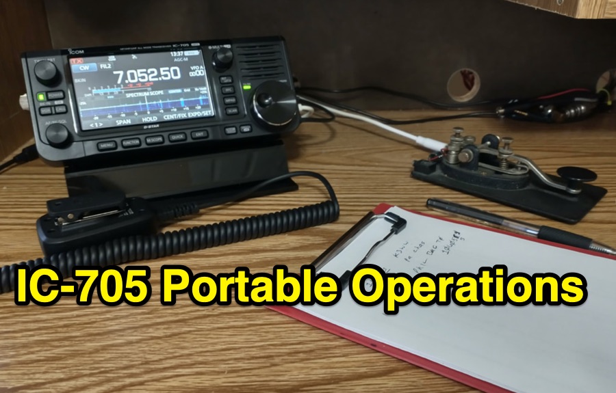 The ICOM IC-705, a popular QRP transceiver for portable operations, often presents unique challenges for field deployment. This resource details practical solutions for common portable setup issues, particularly for _Parks on the Air_ (POTA) activations. It describes a custom bracket for connecting antennas to the IC-705 through a backpack's antenna flap, utilizing a BNC female-to-female chassis mount connector to mitigate cable tangles. The author shares experiences with a DIY magnetic loop antenna, noting its ease of tuning with the IC-705 and successful CW contacts on 40 and 20 meters over distances exceeding **1000 miles**. Another modification presented is a strain relief solution for the microphone cord, replacing the standard spring clip with an easier-to-attach method. The page also mentions using a _Wolf River Parks antenna_ for POTA activations and references the QRPGuys DS-1 antenna as another portable option. Firmware updates and integration with an LDG Z11-Pro II auto-tuner are also discussed.
 -
 The article explores the concepts of return loss, VSWR, and S11 within the context of microwave engineering, highlighting the confusion arising from their definitions. It clarifies that these parameters, while seemingly distinct, fundamentally describe the same phenomenon related to wave reflection and transmission in microwave circuits. The discussion emphasizes the historical context and mathematical relationships among these terms, revealing that their interpretation can vary significantly across different engineering disciplines. Ultimately, it advocates for a pragmatic approach to using these parameters based on familiarity rather than strict definitions.
 -
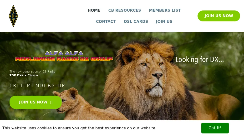 The Alfa Alfa (AA) DX Group, established on March 1, 1974, in the Netherlands, is presented as the pioneering Dutch 27mc DX group. It details the group's historical significance, particularly its revolutionary use of the '000' club callsign (19AA000) which influenced international 11-meter group callsign structures. The resource outlines the group's re-establishment in 2024, inviting new active CB operators and _Short Wave Listeners_ (SWL) to join its ranks, emphasizing a free worldwide membership model. Membership requirements are specified, focusing on active participation with an assigned AA callsign. The group provides QSL card management services, with options for direct QSL requests requiring **3 USD** and a Self-Addressed Envelope, or **4 USD** via PayPal for expenses. It also mentions upcoming initiatives like an _AA DX Contest_ and an award program, with sections for certificates and plaques currently under construction. The site also lists useful CB resources, including an 11M DX Cluster and an 11M Callsign Database, and provides contact information for the founder, 19AA001 Mr. Theo, and the Worldwide QSL Manager, 178AA001 Mr. Emil, based in Bulgaria.
 -
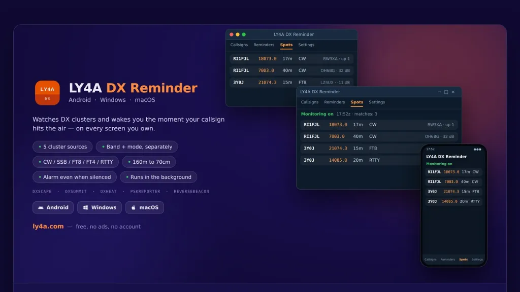 The LY4A DX Reminder application monitors five distinct DX cluster sources—DXScape, DXSummit, DXHeat, PSK Reporter, and Reverse Beacon—to alert amateur radio operators when a specific call sign appears. It supports a wide range of bands from 160 meters to 70 centimeters, including 60m, 6m, 2m, and 70cm, accommodating **CW**, SSB, FT8, FT4, and RTTY modes. The software operates in the background, checking clusters at user-defined intervals of 1, 5, 10, or 30 minutes, and persists across device restarts. Alarm functionality is robust, activating even if the mobile device is silenced, by utilizing the alarm channel and illuminating the locked screen. On desktop platforms, notifications remain active in the system tray. Users can directly manage alarms—stopping, snoozing, or deleting them—from the notification interface, enhancing operational flexibility during DX pursuits. Available in 15 languages, including English, Italian, German, and Spanish, the application is provided free of charge and without advertisements. It offers optional donation support for continued development. Installation instructions are detailed for Android, Windows 10/11 (64-bit), and macOS 12+, addressing common system security prompts for unsigned applications.