Search results
Query: RF loss
Links: 78 | Categories: 0
-
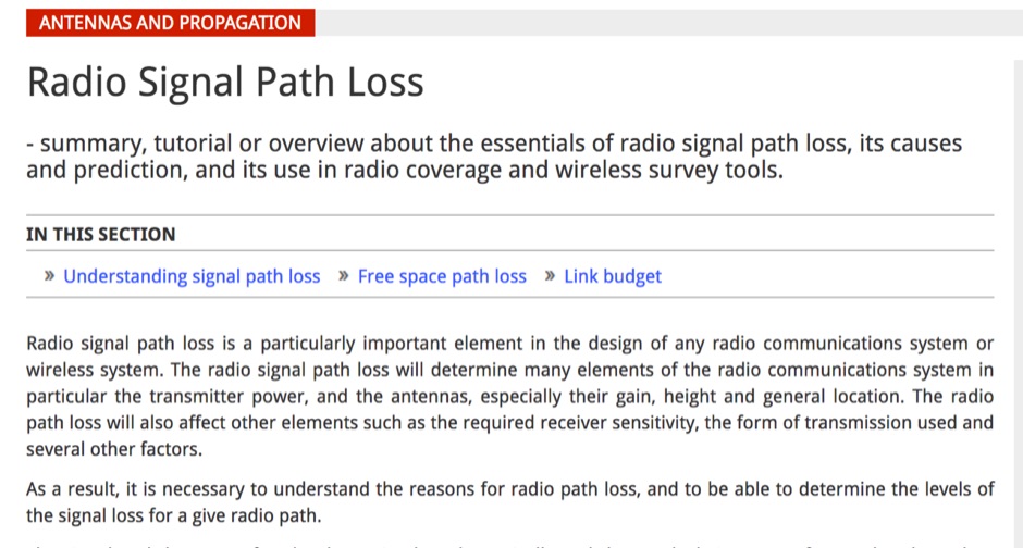 Article about the essentials of radio signal path loss, its causes and prediction, and its use in radio coverage and wireless survey tools
 -
 Operating an amateur radio station effectively requires reliable coaxial cable to minimize signal loss between the transceiver and antenna. SIVA Cavi, an Italian manufacturer, produces a range of coaxial cables, including specific 50 Ohm low-loss types suitable for amateur radio applications. Their product line features cables like **RG 58 SHF1**, **RG 213 SHF1**, and **RF 400 SHF1**, which are commonly deployed in HF and VHF/UHF setups. The company also offers specialized cables such as the **HF 214 UF Ultraflex**, a high-performance broadband low-loss 50 Ohm cable designed for flexibility and reduced attenuation across various amateur bands. These cables are engineered with solid or foam dielectric materials, impacting their electrical characteristics and suitability for different power levels and frequency ranges. For instance, foam dielectric cables often exhibit lower loss at higher frequencies, a critical factor for VHF/UHF operations. Beyond amateur radio, SIVA Cavi manufactures cables for digital video broadcast, offshore marine use, and fire detecting systems, demonstrating a broad engineering capability in coaxial cable technology.
 -
 Explains the fundamental purpose of a repeater, detailing how these automated relay stations overcome distance and terrain limitations for VHF/UHF communications. It traces the historical development from early Bell Telephone Labs "relay" stations in 1922 to Art Gentry, W6MEP's, pioneering K6MYK amateur radio repeater in the mid-1950s, which remains active today. The resource clarifies the distinction between simplex and duplex operation, including the unique function of a "parrot repeater" for single-frequency recording and playback. Delving into the internal workings, the guide breaks down a repeater into its core components: the antenna system, feedline (often _Heliax_ or hardline for minimal loss), duplexer, receiver, transmitter, and controller. It emphasizes the critical role of the duplexer in preventing receiver desensitization by isolating transmit and receive signals, even with distinct frequencies. The discussion highlights the importance of high-performance, durable antennas and low-loss feedlines, citing examples of equipment installed in the 1960s and 1970s that are still in perfect working order. Operating a repeater is also covered, with an explanation of frequency offset (e.g., the 600 kHz standard for 2 meters) and the function of _CTCSS_ (PL tone) for access. It outlines standard input/output offsets for various bands, from 6 meters to 23 centimeters, while noting regional variations. The guide also touches on features like autopatch and Digital Voice Recorders (DVRs), providing a solid foundation for understanding repeater technology and usage.
 -
 Operating within the low-frequency spectrum, transformers serve critical roles in antenna systems, particularly for 160m applications. The resource details the construction and performance of 1:1 transformers built on BN-73-202 cores, emphasizing their use as hybrid combiners or phase inverters for RX antenna arrays. Measurements reveal that these transformers exhibit minimal losses, around 0.12 dB at 1.8 MHz, with variations based on wire type and number of turns. The analysis includes comparative data on transformer performance, highlighting the impact of different winding techniques on frequency response. Notably, the use of coaxial cable for winding improves bandwidth while maintaining low-frequency efficiency. The resource also discusses braid breaker transformers, which minimize inter-winding capacitance, achieving low losses around 0.21 dB at 1.8 MHz. These insights are crucial for optimizing low-band antenna systems, allowing operators to make informed decisions regarding transformer design and implementation.
 -
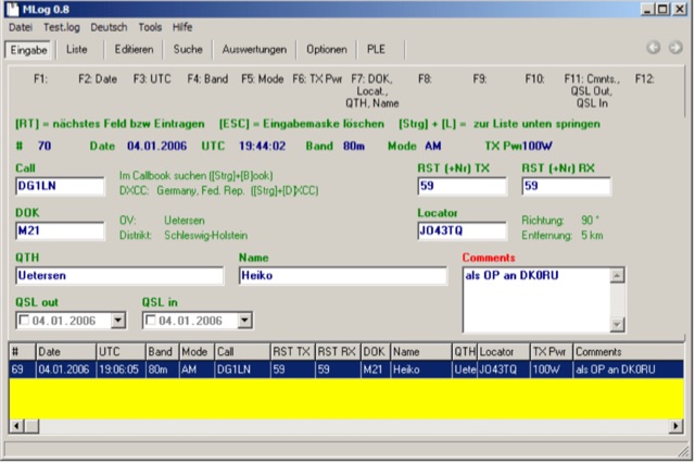 MLog 0.8d is a freeware logging software designed for Windows operating systems (NT, 98, ME, 2000, XP) that facilitates the logging, management, and analysis of amateur radio QSOs. It features a customizable input mask for rapid contest logging, a robust search function for existing contacts, and immediate data storage in CSV format to prevent data loss. The software also includes a double-check mechanism against reference logs during callsign entry, integrated DXCC information, and a "magic field" for streamlined data input, all within a single-window interface. Key functionalities include graphical QSL card management via _QSL-Collection_, CW output through soundcard or PC speaker, and direct access to _Radio Amateur Callbook_ data. MLog supports transceiver control via _Ham Radio Deluxe_ URLs, offers a detailed world map with locator conversions, and can launch _VOACAP_ through _HamCap_. It provides extensive data analysis options for QSLs, _Locator_ large fields, _DOKs_, _DXCCs_, QSO counts, and user-defined contest evaluations, alongside flexible import/export capabilities for various log formats.
 -
 Steve Nichols, G0KYA, presents a practical examination of ground systems for vertical antennas, drawing heavily on the empirical research of Rudy Severns, N6LF. He explains that a robust radial field is crucial for ground-dependent verticals, effectively replacing the antenna's "missing half" and mitigating severe RF absorption in lossy soil. Nichols clarifies that surface radials do not strictly require a quarter-wavelength; instead, deploying a minimum of 16 to 32 shorter wires often yields superior results compared to fewer, longer ones. The presentation also addresses the common SWR paradox: a poor ground might show a perfect 1:1 match, but adding radials, while potentially raising the SWR to around 1.4:1, significantly improves true radiation efficiency. Nichols defines counterpoises as elevated wire networks that substitute for earth connections, offering solutions for limited-space installations, such as the **Folded Counterpoise (FCP)** for 160 meters. This resource provides actionable engineering data for optimizing vertical antenna performance.
 -
 This article presents the C-Pole antenna project, a compact, ground-independent vertical antenna designed for amateur radio operators. It features a folded half-wave dipole configuration that eliminates the need for radials, making it suitable for various locations, especially in deed-restricted areas. The C-Pole offers efficient performance with a 2:1 SWR bandwidth of approximately 3%, and it can be easily constructed using common materials. Additionally, the article discusses practical aspects such as feed-point impedance transformation and balun design to optimize functionality and minimize losses.
 -
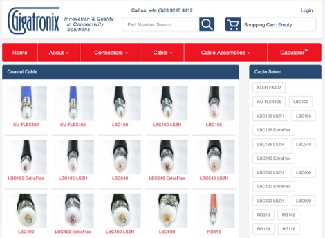 Gigatronix manufactures thousands of coaxial connector styles for stock, including cable fixing, PCB, panel mount, and adaptors. Precision 12G SDI Coaxial Connectors are designed to fit an extensive range of broadcast cables, compliant with **SMPTE ST2082-1 4K single channel** specifications. The company offers an online configurator, "Cabulator," for custom coaxial cable assemblies, streamlining specification and purchase. This includes **IPX / UFL micro-coaxial cable assemblies** configurable with SMA, TNC, and BNC panel fixing connectors. Stock assemblies, tooling, and accessories like strain relief boots are also available. The Resource Hub provides articles, product focus information, and general reference materials for technical details.
 -
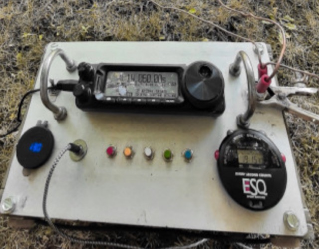
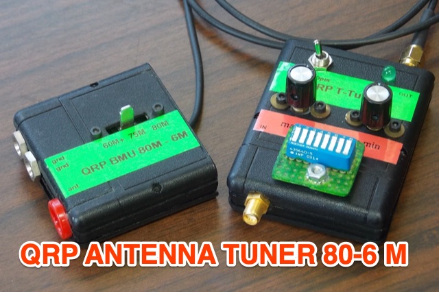 In the pursuit of an affordable matching and SWR indication solution for the Pixie-based transceiver system this T-Tuner and SWR bridge unit, while not groundbreaking, proves to be a cost-effective performer. With real-world impedance testing yielding a worst-case loss below 0.9 dB, the unit efficiently matches all bands on 80 M to 10 M ham bands, making it a valuable addition to the QRP system.
 -
 The multiband tuned doublet, or center-fed Zepp, is a simple and efficient HF antenna that operates effectively across most amateur bands using a balanced parallel-wire feedline and antenna tuner. Unlike coax-fed dipoles, it tolerates impedance mismatches with minimal loss. By selecting suitable feedline and dipole lengths, one can achieve stable multi-band operation. While it doesn’t match monoband Yagis, it offers excellent performance, low cost, and broad coverage. Its radiation pattern and efficiency vary with frequency, but it remains a practical and versatile solution for HF operators.
 -
 The author shares a unique experiment with a 200ft Grasswire antenna—laying wire directly on the ground. Despite inherent losses, the setup enables successful radio communication with a Kentucky station, highlighting the antenna's practicality for portable use with minimal power.
 -
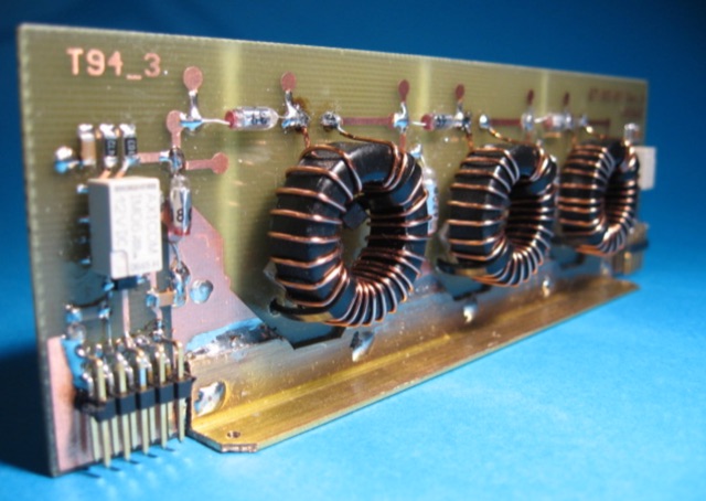 This article explores the nuanced design challenges of Band Pass Filters (BPF) in radio receivers, balancing low insertion loss, high stop band rejection, and narrow bandwidth. The focus is on the "Series-Trap, Shunt-C" topology, resonator count impact, and meticulous layout design for superior stop band performance across various frequency bands
 -
 WB5NHL describes setting up a 160-meter antenna on a small suburban lot, where standard options like Beverage antennas and 1/4 wavelength verticals require extensive space and ground systems. Instead, Guy Olinger's Folded Counterpoise (FCP) provides a solution. The FCP minimizes ground losses by using a folded wire design, allowing effective antenna placement in limited space. The FCP, fed with an isolation transformer, enabled WB5NHL's first 160-meter antenna installation, offering improved performance despite space constraints.
 -
 This document provides comprehensive guidance on modeling and constructing multiband dipole antennas using traps. It addresses common segmentation issues in EZNEC modeling software, recommends optimal segment lengths for trap models, and compares trapped dipoles with paralleled multiband dipoles. While trap dipoles are significantly shorter, they exhibit lower gain and narrower bandwidth. Detailed instructions for building weatherproof coaxial traps include material lists, construction steps, and tuning methods. The guide notes that properly constructed coaxial traps introduce only minimal signal loss (0.6 dB) while offering practical multiband performance in a compact design.
 -
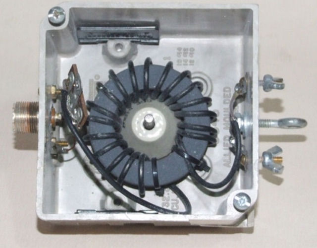
 The article by Guy Olinger, K2AV, published in the May/June 2012 National Contest Journal, introduces the Folded Counterpoise (FCP), a compact 516-foot single-wire counterpoise elevated at 8 feet, designed for 160-meter operations on small lots like 100x150-foot backyards. Originating from efforts to revive Top Band for W0UCE on a postage-stamp property, the FCP uses strategic folds to cancel ground fields within 33 feet of center, minimizing losses to 0.13-0.53 dB—outperforming sparse or on-ground radials by up to 15 dB in poor soil—while mimicking opposed radials for efficient feedpoint impedance. Paired with a critical 1:1 or 4:1 isolation transformer (e.g., trifilar on T300-2 toroid) to block common-mode currents on coax feeds, it delivers proven results: K2AV's #8 North America low-power contest score, 7+ dB gains at W4KAZ and K5AF, and over 10,000 global web hits for DIY instructions using bare 12 AWG wire and weatherproof enclosures. Ideal for acreage-challenged hams, the FCP also excels on 80 meters with scaled dimensions, offering a low-loss alternative where full radials are impractical
 -
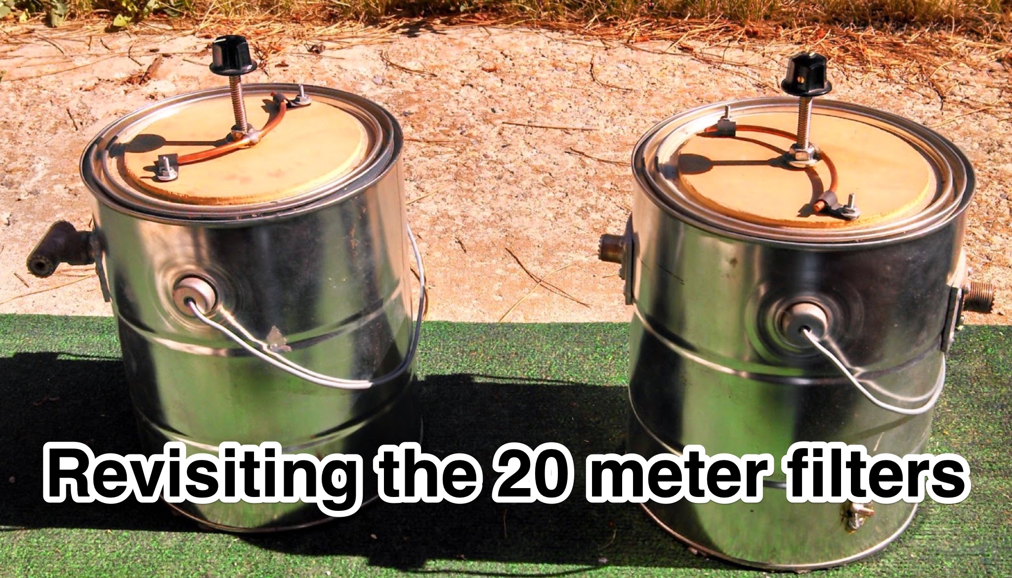
 Learn how to enhance your 160 meter reception by building and using a custom band pass filter. Discover how this filter can reduce interference from strong AM broadcast signals, improving the overall performance of your receiver. Find out about the challenges of creating a filter that balances signal loss and attenuation at specific frequencies, and how it can benefit hams operating near powerful transmitters. Whether you're experiencing IMD issues or looking to optimize your 160 meter setup, this article provides practical insights and solutions for ham radio operators.
 -
 This project involved designing a 7-pole Chebychev broadcast band filter to address severe interference issues caused by a new horizontal loop antenna on the KN-Q7A transceiver. The interference overwhelmed the transceiver’s front end, so a custom filter with a 3.5 MHz cutoff was built using silver mica capacitors and type 6 T130 toroidal cores. Encased in a diecast box with SO239 sockets, the filter blocks strong signals from the broadcast band, achieving over 100 dB attenuation. Tested up to 100W, it reduces interference effectively while maintaining low insertion loss across HF bands.
 -
 This page discusses the construction and design of a shortened 2-element Yagi antenna for the 40-meter band, focusing on the driven element. The author shares insights on adding hats to the coil to reduce losses and improve performance. The article also mentions the use of EZNEC modeling software and an AIM4170 analyzer for tuning. Amateur radio operators interested in such antenna design and optimization for the 40-meter band can find useful information and practical tips on this page.
 -
 This project documents the construction of a coaxial 50 MHz notch filter to eliminate inter-band interference between 50 and 70 MHz transceivers. Using RG-213 coax and based on quarter-wave stubs, the filter achieved a 44 dB attenuation at 50.060 MHz while maintaining low insertion loss on 70 MHz. A dual-stub design broadened the notch response and minimized attenuation on 70 MHz to 0.2 dB. Fine-tuned using an FA-NWT network tester and Elecraft XG3 signal source, the filter effectively resolved interference for seamless dual-band operation.
 -
 This excel workbook addresses the issue of power loss in transmission lines with complex characteristic impedance ZoZo​. It illustrates the discrepancy between actual loss (0.35 dB) and matched line loss (0.6 dB) using a simplified example, highlighting potential software tool limitations. The RF Feedline Power-Loss Calculator provides accurate end-to-end loss assessments for both microwave and RF applications. This tool is suitable for engineers and students and is compatible with Windows versions of Excel 2016 or later, though it is not compatible with Macintosh systems.
 -
 This webpage caters to EMRFD owners, offering insights into building popcorn receiver band-pass filters with Ladpac programs and EMRFD Chapter 3 knowledge. Through practical experiments and Ladpac tools, the author explores coupling capacitors' impact on filter response and return loss optimization. The content emphasizes empirical approaches, encouraging builders to embrace experimentation and learn from mistakes. Detailed examples and workflow suggestions aid hobbyist-level designers in creating customized filters, fostering a deeper understanding of filter design principles.
 -
 The website offers technical musings related to amateur radio, with a focus on measuring insertion loss and checking matching. It provides insights and tips for ham radio operators looking to analyze RF devices and circuits effectively.
 -
 For phased C-Poles, matching choke baluns are essential to maintain intended phasing, beam pattern, and gain. The author uses a low-loss, ferrite-core balun design with 19 turns of RG-174/U coax for optimal performance.
 -
 This comprehensive article dispels common misconceptions about Standing Wave Ratio (SWR) in amateur radio. The author explains that SWR is not an antenna property but a measure of the entire antenna system, representing the mismatch between transmission line and load impedance. Contrary to popular belief, modest SWR values (under 3:1) typically cause minimal power loss in HF applications. The article demonstrates mathematically why obsession with achieving 1:1 SWR is often unnecessary, explains when SWR matters more (QRO, QRP, VHF/UHF), and explores effective matching techniques including proper ATU placement and quarter-wavelength transformers.
 -
 Operating amateur radio satellites presents unique challenges, particularly concerning antenna design and signal propagation. Juan Antonio Fernández Montaña, EA4CYQ, recounts his three-year journey into satellite communication, starting with initial guidance from EB4DKA. His early experiments involved a portable 1/4 wave VHF antenna with four 1/4 wave ground planes, designed for hand-held use to adjust polarity. This setup, paired with an FT-3000M transceiver, allowed full-duplex operation on **VHF** transmit and **UHF** receive, proving effective for early contacts on satellites like AO27, UO14, and SO35. EA4CYQ's experience highlights the critical role of coaxial cable loss and antenna polarization. After encountering significant signal degradation with longer RG213 runs, he experimented with a 1/2 inch commercial cable, noting improved reception but persistent fading due to varying satellite polarities. This led to the construction of an **Eggbeater II** antenna, an omnidirectional UHF design offering horizontal polarization at the horizon and circular right polarization at higher elevation angles. Subsequent modifications resulted in the directional **TPM2** antenna, which provided sufficient gain for LEO satellites with a wide 30-degree lobe, enabling consistent contacts from his home station. The article concludes with practical insights on the performance of the Eggbeater II for both UHF and VHF, and the TPM2 for UHF, emphasizing their utility for portable and fixed operations. EA4CYQ's journey underscores the iterative process of antenna development and the importance of adapting designs to overcome real-world propagation challenges in satellite communications.
 -
 The article discusses the construction of a UHF band-stop stub filter to protect an APRS receiver from potential damage during a balloon launch. The author, who communicates using a 441 MHz transmitter, needed to ensure that the RTL-SDR dongle receiving at 144 MHz wouldn't be damaged by the transmissions. The solution involved creating a quarter-wavelength open stub filter using coaxial cable, which attenuates the 441 MHz signal while allowing the 144 MHz signal to pass through. The filter's design is based on the principles of constructive and destructive interference, with careful measurement and trimming to achieve the desired frequency response. The final filter provided 34.8 dB of insertion loss at 441 MHz and minimal loss at 144 MHz, effectively protecting the receiver.
 -
 The FF-501DX LPF, a high-performance VHF and 10m filter, was obtained at a friend's SK sale. After becoming more active on 10m, the author reexamined the LPF and discovered it to be of high quality. The filter's efficiency was outstanding and the return loss/VSWR was better than estimated. The LPF was connected to a Bird 50R dummy load to evaluate insert loss, cutoff, attenuation over 70MHz, and return loss. The original specifications were found in an old radio magazine, along with a link to the original one-page information sheet. Comparing the results to the original specs confirms the LPF's quality.
 -
 Demonstrates the design and modeling of a **160m** vertical antenna, dubbed the "WindoVert," specifically for urban amateur radio operators with limited space. The resource covers the theoretical underpinnings of antenna height and radiation patterns, using EZNEC software to analyze current distribution and 3D radiation patterns for various configurations, including a Marconi-style "T" antenna. It details the integration of existing antenna components, such as a Carolina Windom balun and line isolator, into the new vertical setup, and the practical measurement of feedpoint impedance using an antenna analyzer. The article further explores the challenges of achieving low-angle radiation on Top Band, emphasizing the critical role of radial systems and mitigating ground loss. Author VE1ZAC presents EZNEC models illustrating the impact of lumped components and discusses the practical considerations of resonant frequency adjustment and impedance matching for **QRP** operation. The text details the calculation of required loading coil inductance and capacitance, and shares field results, including successful DX contacts on 160m and unexpected excellent performance on 30m.