Search results
Query: antenna modification
Links: 60 | Categories: 6
-
 The Dipole Bazooka Antenna for 40 meters is a popular choice among amateur radio operators. Its design allows for easy construction using materials like RG58 coaxial cable and PVC. Measurements are calculated using specific formulas; for instance, at a frequency of 7,100 MHz, the total length is approximately 19.74 meters. This antenna offers a performance range of 97% to 99%, with an impedance of 49 to 52 ohms. Additionally, it can handle up to 1 kW of power and requires no modifications for connection.
 -
 This page discusses the purchase of a fiberglass push-up mast for portable operations in the ham radio hobby. The author shares their experience with the MaxGain Systems MK-4-HD mast, highlighting its versatility for both home and on-the-go setups. They also detail modifications made to the mast base and provide insights on tube sizes for different antenna types. The content is useful for hams looking to improve their portable station setup and optimize antenna performance in various environments.
 -
 The article explains how to adapt the YAESU FT817 transceiver so that it can be used to control Kuhne electronic transverters by transmitting at +12V via the coaxial wire. Different FT817 versions imply that some of the modification proposals that have been made so far don't apply to everyone. This tutorial provides a workaround that works with all FT817 models. It makes use of the external ACC socket, connecting an interior tiny circuit board to two thin wires. Follow ON7WP's instructions for using the rear antenna socket.
 -
 The ICOM IC-705, a popular QRP transceiver for portable operations, often presents unique challenges for field deployment. This resource details practical solutions for common portable setup issues, particularly for _Parks on the Air_ (POTA) activations. It describes a custom bracket for connecting antennas to the IC-705 through a backpack's antenna flap, utilizing a BNC female-to-female chassis mount connector to mitigate cable tangles. The author shares experiences with a DIY magnetic loop antenna, noting its ease of tuning with the IC-705 and successful CW contacts on 40 and 20 meters over distances exceeding **1000 miles**. Another modification presented is a strain relief solution for the microphone cord, replacing the standard spring clip with an easier-to-attach method. The page also mentions using a _Wolf River Parks antenna_ for POTA activations and references the QRPGuys DS-1 antenna as another portable option. Firmware updates and integration with an LDG Z11-Pro II auto-tuner are also discussed.
 -
 This report details a modification of a Diamond V2000 antenna, replacing its original two 0.50 m radials with two 1.55 m radials. Initial M5-threaded rods failed to fit; the housing required M6 threads. Custom radials were made using 8 mm OD aluminium tubing and M6-threaded stainless steel ends, secured with nuts machined to 9 mm. SWR issues on 6 m (>2:1) were largely due to a poor counterpoise connection, resolved during reassembly. NanoVNA measurements showed no adverse effects on 2 m or 70 cm. The final setup retains the two 1.55 m radials and original counterpoise. Other operators reported SWR degradation with similar mods—sometimes fixed by adding capacitance—but this was not observed here.
 -
 Operating amateur radio satellites presents unique challenges, particularly concerning antenna design and signal propagation. Juan Antonio Fernández Montaña, EA4CYQ, recounts his three-year journey into satellite communication, starting with initial guidance from EB4DKA. His early experiments involved a portable 1/4 wave VHF antenna with four 1/4 wave ground planes, designed for hand-held use to adjust polarity. This setup, paired with an FT-3000M transceiver, allowed full-duplex operation on **VHF** transmit and **UHF** receive, proving effective for early contacts on satellites like AO27, UO14, and SO35. EA4CYQ's experience highlights the critical role of coaxial cable loss and antenna polarization. After encountering significant signal degradation with longer RG213 runs, he experimented with a 1/2 inch commercial cable, noting improved reception but persistent fading due to varying satellite polarities. This led to the construction of an **Eggbeater II** antenna, an omnidirectional UHF design offering horizontal polarization at the horizon and circular right polarization at higher elevation angles. Subsequent modifications resulted in the directional **TPM2** antenna, which provided sufficient gain for LEO satellites with a wide 30-degree lobe, enabling consistent contacts from his home station. The article concludes with practical insights on the performance of the Eggbeater II for both UHF and VHF, and the TPM2 for UHF, emphasizing their utility for portable and fixed operations. EA4CYQ's journey underscores the iterative process of antenna development and the importance of adapting designs to overcome real-world propagation challenges in satellite communications.
 -
 Details the construction and performance of a phase-controlled receiving array, specifically a **MicroSWA** variant, optimized for QRP low band fox hunting on 40M and 80M. The resource documents the author's iterative design process, addressing significant regional noise challenges encountered during 0100-0230 UTC fox hunt periods. Initial experiments involved a director wire on a 40M vertical, yielding limited improvement, prompting a shift towards advanced null-steering techniques. The project leverages concepts from Victor Misek’s "The Beverage Antenna Handbook" and Dallas Lankford’s extensive work on phased receiving antennas for urban lots. A key modification involved integrating a new passive phase control box and a push-pull **Norton common base preamp** using 2N5109 transistors, designed for high third-order intercept performance to maintain weak signal integrity amidst strong adjacent signals. The system incorporates Faraday-shielded transformers with RG174 primaries on -75 ferrite cores, housed in ABS plastic pipe. Performance tests confirmed the MicroSWA's ability to produce deep, steerable nulls, achieving approximately 30 dB noise reduction on 160M, 80M, and 40M. This enabled detection of QRP signals undetectable on conventional transmit antennas. The final unit includes front panel controls, a 10-11 dB preamp, and a robust power conditioner, demonstrating effective noise mitigation for challenging low band QRP operations.
 -
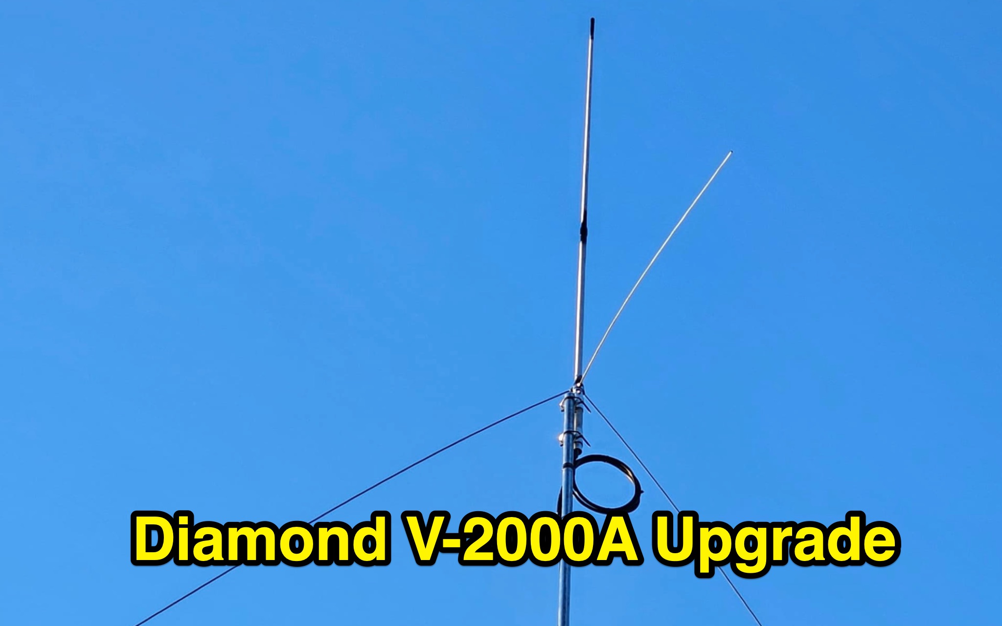 Learn how to enhance the performance of your Diamond V2000A antenna by optimizing the length of the radials. Discover a cost-effective method to create improved radials using simple materials like aluminum tubes and bolts. Explore the benefits of this modification for 6m band, unlocking triband capabilities and better SWR. Find out how a ham radio operator from Europe successfully upgraded their V2000 antenna and achieved impressive results. Save money by DIY-ing your radial enhancements instead of purchasing expensive replacements.
 -
 VE1ZAC's analysis details the performance of **MFJ927** and **SGC239** autotuners with portable HF vertical antennas, specifically comparing 31 ft and 43 ft configurations. The resource originated from challenges encountered during a Maritime QSO Party roving operation, necessitating a lightweight and easily deployable antenna system. Target bands for the contest included 80, 40, 20, 15, and 10 meters, with a maximum power handling of 100 W CW. The author utilized a 30-foot carbon fiber push-up pole to support a vertical wire element, noting its 2 lb weight and reliability. EZNEC modeling was employed to predict performance, showing favorable results for a 30-foot vertical with elevated radials, particularly on 40 and 20 meters. Feedpoint impedance measurements, taken with an AIM4170C, are presented for various HF bands, both with and without a 41-foot RG6 stub designed to reduce reactance on 80 and 20 meters. The stub significantly improved matching on these bands, easing the tuner's workload. Operational tests revealed issues with the MFJ927's reliability during contest setup, leading to reliance on the K3's internal tuner. The SGC239, tested post-contest, performed flawlessly. A detailed side-by-side comparison covers mechanical aspects, connection options, power bias, impedance range, board quality, and documentation. Modifications to the MFJ927, including a new aluminum case, white paint for heat reduction, and upgraded impedance-measuring resistors, are also described.
 -
 This study analyzes the antenna pattern of the Utah Amateur Radio Club's 146.760 MHz repeater following antenna relocation in 1997. Noting degraded transmission toward the north, a customized signal mapping system using a Yaesu FT-817, GPS, and software was developed to log real-time signal data. Calibration techniques extended the radio's signal range, enabling precise field measurements. The method allowed continuous signal strength monitoring while driving, revealing anomalies in coverage likely due to tower modifications. Findings helped assess and visualize the antenna’s actual radiation pattern and highlighted environmental impact on signal distribution.