Search results
Query: dipole 10
Links: 128 | Categories: 1
Categories
-
 This antenna consists of 4 resonate dipoles made from 12 insulated copper electrical wire. The dipoles are resonate on the following bands: 6 meters, 10 meters, 12 meters and 17 meters.
 -

-
 A simple 7 bands off-center dipole wire antenna designed to work on 80 meters band and that can cover also 40m 30m 20m 15m 12m 10m with acceptable SWR
 -
 Demonstrates the product line of _LZ Antenna Ltd._, a Bulgarian manufacturer specializing in amateur radio antennas and custom electronic devices. The company focuses on robust, high-quality HF multiband Yagi and vertical antennas, leveraging over 20 years of experience from founder Georgi Georgiev in radio amateur development. Featured models include the LZA 8-4, LZA-10-3, and the LZA-7-3A WRTC 2022, alongside various rotary dipoles like the LZA1 40/30m. Provides specifications for several Yagi antennas, such as the LZA-9-5, LZA-13-7, and LZA-6-3 (a 6-element, 3-band design). The company emphasizes applying "leading edge technology" to high-frequency communication equipment production, with products designed for durability and performance. The LZA-10-5 Yagi offers **12.5 dBi** gain on 10m, while the LZA-13-7 provides **13.2 dBi** on 20m, showcasing competitive gain figures for DXing and contesting.
 -
 Presents a construction project for a linear-loaded 40-meter rotatable dipole, detailing the design evolution from mid-element coils to 300-ohm twinlead loading. It covers material selection, including repurposed fishing poles and EMT conduit, and outlines the assembly process for the antenna elements and mounting plate. The resource provides specific measurements for element lengths and linear loading sections, along with SWR plots demonstrating the antenna's resonance at 7.035 MHz with a 1.1:1 SWR, and bandwidth up to 7.120 MHz below 2:1 SWR. The article documents the antenna's performance during various RTTY and CW contests, including the SARTG RTTY and SCC RTTY contests in August 2006, and the ARRL DX CW and CQWW WPX RTTY contests in February 2007. It reports successful operation at 500-1000W, noting improved performance after replacing a faulty coax cable. Specific DX contacts from British Columbia, including stations in Europe and South Africa, are listed, illustrating the antenna's capability despite its shortened length and relatively low height of 55 feet. The content highlights practical considerations such as weatherproofing the connections and supporting the fiberglass elements to prevent sagging. It also includes a brief comparison to an inverted-V at similar height and a ground-mounted vertical, noting the rotatable dipole's quieter reception. The author shares insights into the iterative design process and tuning adjustments made to achieve optimal resonance.
 -
 Constructing a portable, high-gain antenna for _AO-40_ satellite operations presents unique challenges, particularly regarding mechanical stability and parabolic accuracy. This resource details the build of a 1.2-meter "brolly dish" antenna, utilizing a non-conducting fiberglass umbrella frame as its foundation. The project outlines a method for achieving a parabolic shape using stressed aluminum fly screen mesh, guided by practical geometry and a temporary dowel template. Key steps include selecting an appropriate umbrella with a suitable f/D ratio (ideally >0.25), removing the original fabric, and precisely cutting and attaching eight segments of fly screen to the struts to form the reflective surface. The construction process, which took approximately five hours for the author, _G6LVB_, resulted in a dish with an f/D of 0.27 (depth=270mm, diameter=1160mm, f=310mm). The article also describes a modification to a _TransSystem AIDC_ feed, incorporating a PCB reflector behind the dipole for easier mounting. Performance tests at a squint angle of 15 deg and a range of 50,000km yielded a signal-to-noise ratio of 33dB on the S2 beacon and 23dB for SSB signals, indicating strong reception. The author notes that the modified umbrella may not close fully without risking surface disfigurement.
 -
 The ZS6BKW antenna, a popular multiband wire antenna, offers improved band matching compared to the traditional G5RV. This construction guide details the process, beginning with specific dimensions: 13.11 meters (43 feet) for the 450-ohm ladder line and initial dipole arm lengths of approximately 14.8 meters each. It emphasizes the critical role of an _antenna analyzer_ for accurate tuning, particularly for determining the velocity factor of the ladder line and achieving a 1:1 impedance match. The article outlines the materials required, including a 1:1 current balun, 450-ohm window line, wire for the dipole arms, and a 50-ohm non-inductive resistor for testing. It provides a step-by-step procedure for cutting the ladder line to its electrical half-wavelength, explaining how to calculate the velocity factor using measured and free-space frequencies. For instance, a measured 50-ohm impedance at 12.54 MHz with a calculated free-space half-wavelength frequency of 11.44 MHz yields a velocity factor of 0.91. Final adjustments involve hoisting the antenna to its operational height and fine-tuning the dipole arm lengths to achieve optimal SWR, specifically targeting 14.200 MHz. The _ZS6BKW_ design is noted for its performance on 80m, 40m, 20m, 10m, and 6m, though it is not optimized for 15m operation. The author, _VK4MDX_, shares practical tips for durable construction using stainless steel wire and cable clamps.
 -
 Demonstrates the design and construction of a compact, portable multi-band mini-delta loop antenna, specifically optimized for /P (portable) operations from remote locations like Scottish islands. The resource covers the theoretical underpinnings of half-wave loops, contrasting closed and open configurations, and then details the application of a folded dipole principle to achieve a 50-ohm match for direct coax feed. It presents empirical formulas for calculating element lengths, considering the velocity factor of common wire types, and provides a detailed example for a 20m (14.175 MHz) version. The article includes a comprehensive table of dimensions and allowances for a five-band (20m, 17m, 15m, 12m, 10m) mini-delta beam, along with construction hints for the central support and balun. It specifies a 1:1 trifilar balun wound on a ferrite rod and describes the antenna adjustment process using an _MFJ-259B Antenna Analyser_. Initial test results indicate an SWR of 1:1 at resonance and a bandwidth of approximately 240 kHz on 20m, even at a low height of five feet above ground. The distinctive utility lies in its focus on a practical, easily deployable beam antenna for portable DXing, offering a viable alternative to more complex or larger arrays.
 -
-
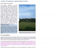
 A lightweight inverted vee antenna that can be supported by a 10 metre long fiberglass squid pole. The antenna is designed to cover 10, 15, 20, 40 and 80 m bands.
 -
 Over 1,000 stations in approximately 60 countries were worked using this modified twin-lead folded dipole, demonstrating its effectiveness with just 4 watts on 20 meters. This design, adapted from an ARRL Handbook concept, eliminates the shorting strap found in traditional folded dipoles, simplifying construction while maintaining performance. It utilizes readily available 300-ohm TV antenna feeder ribbon, making it a cost-effective solution for radio amateurs. The antenna's robust construction allows it to handle up to 100 watts without issues, even without a **balun**. The inclusion of a variable trimmer capacitor at the stub provides flexibility for tuning across different frequencies within a band, a practical feature for operators using transceivers like the Icom 735. Formulas are provided to calculate the precise dimensions for any desired operating frequency, enabling customization for various **HF bands**.
 -
 An Off-center-feed antenna that covers 80, 40, 20, 17, 15, 12, 10, and 6 meters
 -
 This article describes a project of asymmetrical hatted vertical dipole, a portable antenna that can be used for field day operations, sota, campings or even for fixed installations. This is a freestanding 20-10m antenna that is really easy to build, easy to tune and relatively easy to carry.
 -
 How to operate on 10 and 20 meters in limited space with this trapped dipole.
 -
 The G5RV multiband HF antenna, designed by Louis Varney (G5RV) in 1946, is a popular compromise antenna offering good overall performance on most HF bands when paired with an external antenna tuner. The basic full-size G5RV measures 102 feet across the top for 80 through 10 meter operation and is fed at the center via a 34-foot low-loss feed-stub. This interaction between the radiating section and the feed-stub facilitates matching across 80-10 meters with a standard tuner, often eliminating the need for ladder line directly to the shack. The antenna's design center frequency is 14.150 MHz, configured as a 3/2-wave dipole on 20 meters, with its 102-foot length derived from long-wire antenna formulas. Construction details emphasize the matching section, which can be open wire, ladder line (window-type), or TV twin lead. Each type has a specific velocity factor (VF) affecting its physical length for an electrical half-wave on 14 MHz; for instance, open wire requires 33.7 feet (VF 0.97), ladder line 31.3 feet (VF 0.90), and TV twin lead 28.5 feet (VF 0.82). The article provides formulas for calculating these lengths and discusses the antenna's behavior on individual bands, from 3.5 MHz where it acts as a shortened dipole, to 28 MHz where it functions as two three-half-wave long-wire antennas fed in-phase. Practical construction notes include recommendations for vertical descent of the matching section, sealing the coax junction, providing strain relief, and winding a coaxial choke coil to mitigate common mode current. The resource also presents dimensions for double-size (204 ft) and half-size (51 ft) G5RV versions, along with their corresponding matching section lengths for various line types, making it a versatile reference for hams considering this classic wire antenna.
 -
 A trapped dipole antenna based on the orignal W3DZZ antenna design resonating on 80 40 20 15 10 meters
 -
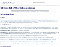 This article explores the Cobra Junior linear loaded antenna for 80m to 10m bands. This antenna is a linear loaded dipole described by W4JOH in 73 magazine June 1997
 -
 Extension to an existing fan dipole originally modeled for 40 20 and 6 meters. This modification will add 80 15 and 10 meter bands.
 -
 Multi-band loft-mounted dipoles for 40, 20, 17, 15, and 10m
 -
-
 An off centre fed dipole, with 10 feet of vertical radiator. It needs no tuner on 40m, 20m and 10m by M0UKD
 -
 The _Italian VHF Beacons_ resource provides a detailed listing of active and QRT amateur radio beacons operating across VHF, UHF, and SHF bands within Italy. Each entry specifies the beacon's callsign (e.g., IQ1SP/B), operating frequency (e.g., 144.411 MHz), QTH locator (e.g., JN44VC), effective radiated power (ERP) in watts, and antenna configuration (e.g., Big Wheel, 4x Dipole, Yagi). This data is crucial for radio amateurs involved in propagation studies, equipment testing, and long-distance (DX) communication on these higher frequency bands, offering fixed signal sources for monitoring. This compilation, last updated in October 2005, serves as a historical snapshot of Italian beacon activity. For instance, it lists several 144 MHz beacons with ERPs ranging from **0.1W** to **10W**, and higher frequency beacons such as I8EMG/B on 1296.880 MHz and I3EME/B on 24192.132 MHz. The inclusion of QRT (Quiet Radio Teletype) status for many entries indicates the dynamic nature of beacon operations over time. Users can utilize this information to identify potential signal sources for band openings or to calibrate their receiving equipment against known transmissions.
 -
 40/20/10 Meter Fan Dipole attic antenna article by KD2GOE
 -
 Experiments on HF antennas for restricted spaces. In this article author experiments antennas for 80-10 meters band having just a very small garden and several restrictions. Basic antennas consists of laded multiband dipoles and fan dipole antennas
 -
 This project details the construction of a **full-sized 40-meter vertical antenna**, born from a renewed interest in 7 MHz operation and a desire for improved effectiveness over simple dipoles. The author, K5DKZ, initially focused on VHF experimentation, which provided an inventory of aluminum tubing and fiberglass spreaders for this endeavor. Before this vertical, K5DKZ utilized an 80/40 meter inverted-vee trap dipole and a 40-meter broadband dipole, but now primarily uses a pair of full-sized, phased, quarter-wave verticals spaced 35 feet apart for serious 40-meter work. The construction involves a base-heavy design for stability, using a 44.5-inch section of 1-1/4 inch steel TV mast driven into 1-3/8 inch aluminum tubing, insulated by a 105-inch section of Schedule 40 PVC pipe. The assembly reaches 31 feet, close to the 32 feet required for a quarter-wavelength on 40 meters, with fine-tuning achieved by winding wire onto a fiberglass spreader. The design is explicitly presented as a foundation for a two-element 40-meter Yagi beam, outlining modifications like substituting aluminum for steel in the base and using an inductive hairpin match for the driven element. The article also discusses tuning considerations for a large 40-meter beam, noting the 100 to 200 kHz upward frequency shift when raised, and suggesting methods for installation on a tower. The author emphasizes the cost-effectiveness and good performance of the monopole approach, especially when multiple verticals are needed.
 -
 Homemade Loaded Coil Dipole ( w8010 diamond ) for 10, 15, 20, 40 and 80 meter
 -
 A home made dipole antenna for 10m, 6m, 4m bands made with two sections of 450 and 300 Ohm ladder lines, cut to achieve acceptable SWRs on all bands
 -
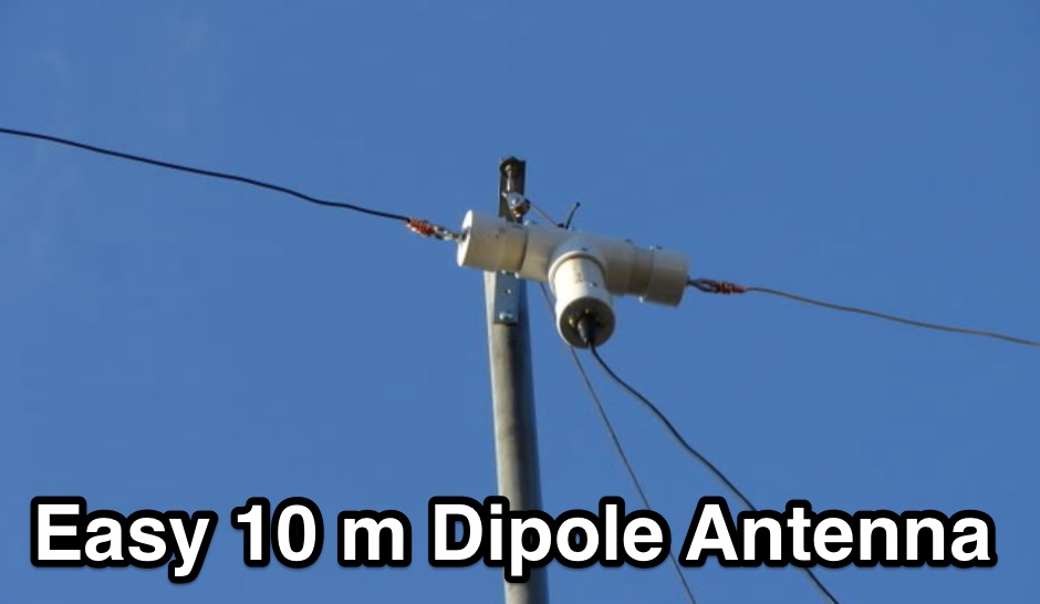
 Only 2x 10ft wide, performance similar to full-size dipole, covers whole band with SWR better than 1:1.2.
 -
 A three band short Vee antenna is feasible with two legs per side on a dipole. 10-15-20 meters by W8HDU
 -
 Homebrew project of a windom antenna, an off center fed dipole, resonating from 10 to 80 meters
 -
 A Co-ax Trap Dipole For 40, 30 and 20 Meters or at last that was the intention
 -
 The X80 multi-band HF vertical antenna, a commercial iteration of the Rybakov design, exhibits a physical length of 5.5 meters, or approximately 18 feet, and is constructed from aluminum tubing. It operates as a non-resonant vertical, requiring an external antenna tuner for impedance matching across its intended operating frequencies. The antenna's design incorporates a 1:4 UNUN at its base, facilitating a nominal 50-ohm feed point impedance for the coaxial cable. Performance observations indicate effective operation on 40 meters, 20 meters, 15 meters, and 10 meters, with reduced efficiency on 80 meters and 160 meters due to its relatively short electrical length for these lower bands. Comparative analysis with a G5RV dipole and a half-wave end-fed antenna reveals the X80 offers a lower take-off angle, beneficial for DX contacts, particularly on the higher HF bands. Field tests conducted with an Icom IC-706MKIIG transceiver and an LDG AT-100ProII autotuner demonstrate the X80's ability to achieve acceptable SWR across 80m through 10m. The antenna's compact footprint and ease of deployment make it suitable for restricted spaces or portable operations, though its performance on 80 meters is noted as a compromise compared to full-size resonant antennas.
 -
 A multiband coax trapped dipole for 10-80 meters bands by DF1PU
 -
 A post about the construction and measurements of a Resonant Feedline Dipole cut for the 10M band
 -
 How to homemade a multi-band HF dipole using 100 meter of speaker wire, 2 strandsm including a homebrew 1:1 choke balun
 -
 Based on a simple project based on a 2 elements Yagi for 20m band, and then becomed a triband yagi with a open-sleeve feed system
 -

-
 This article describes the design and simulation of a multiple dipole antenna for the HF band, using the software MMANA-GAL. The antenna will be designed to operate in the 10, 20, 40 and 80 m bands
 -
 Experimenting vertical wire antennas for 40 and 20 meters supported by balloons resulting in excellent gain in RX and good overall performance against horizontal dipole
 -
 The Superantennas MP-1 portable HF antenna is analyzed for its design and field performance, particularly its high-Q loading coil and 3/8-inch mounting. The review details the antenna's construction, including an 8-inch vertical section, a large-diameter loading coil tuned by a sleeve, and a 4-foot whip that disassembles into six rods for transport. Initial testing with the supplied 10-foot ribbon cable "ground plane" yielded poor SWR and RF hot conditions, indicating an inadequate ground system. Further experimentation with longer radials and resonant counterpoises for each band improved matching and eliminated RF hot issues, but introduced significant operational complexity. The author notes the difficulty in optimizing both counterpoise length and coil setting without an antenna analyzer, and the sensitivity of the MP-1 to counterpoise deployment. The review also discusses the recommendation to tune for maximum received signals rather than minimum SWR, often necessitating an external ATU due to the antenna's typical low impedance. The **MP-1**'s critical dependence on resonant counterpoises for effective operation, especially when elevated, is highlighted as a major drawback for portable use. The author ultimately sold the antenna, concluding that despite its sound technical design, its fussy nature and the need for extensive counterpoise management or an ATU detract from its portability and convenience compared to simpler, less expensive dipole solutions. The **Superantennas MP-1** is deemed a flawed portable antenna, requiring considerable effort to achieve its claimed performance.
 -
 How to build Fan-Dipoles by DK7ZB. Experiences with various band combinations. Not all combinations are working properly. If the frequencies are to close together the impedances will lead to a very bad SWR. This happens with the bands 10-12-15m or 15-17-20m.
 -
 The antenna in this project is a modification of the techniques used to design a multiband fan type dipole with little or no tuning involved having a total space of 105 feet
 -
 A Six-element Yagi Beam for 6 Meter by W1JR proiddes a power gain of 10.2 dB over a dipole it is built on a 24 foot long boom
 -
 An inverted V Dipole antenna for HF bands, working on 10 20 40 and 80 meters band. PDF Presentation
 -
 An experimental prototype of an asymmetrical hatted vertical dipole antenna that can work on HF bands 20 to 10 meters band. The AHVD Vertical dipole is an upside-down T design
 -
 Amateur radio antennas manufacturer based in Italy. Produces HF end-fed, dipoles, and other wire antenna types, mono band and multi band antennas.
 -
 A trap antenna dipole covering two differen bands made reusing an old 160/80m inverted vee antenna.
 -

-
 The OCFD Off-Center-Fed Dipole Antenna is an excellent multiband antenna that is relatively simple to construct, yet gets quite decent performance.
 -
 A simple portable dipole antenna for the 40 meter band using a total lenght of 18 meter. It can be used for 80 to 10 meters coverage using a antenna tuner.