Search results
Query: 28 MHz
Links: 134 | Categories: 1
Categories
-
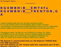 28.222mhz transmitting with 2 watts of power
 -
 W7GJ 50 MHz EME DXpedition July 12 - July 28, 2014
 -
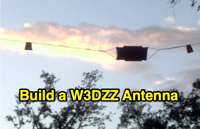 The purpose of this construction is to enable the realization of an HF antenna called W3DZZ with minimal equipment and low cost. It allows traffic on the bands 3.5 / 7/14/21 and 28MHz.
 -
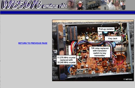 AC7GZ/B is a converted Sharp CB-2460 Citizens Band transceiver operatin on 28.2118 MHz.
 -
-
 This J-Pole is mounted on a fishing rod. The radiator L1 is an isolated copper-wire with a length of 281,5 cm while the quarter-wave matching sector L2 is made with 450-Ohm-Wireman-cable
 -
-
-
-
 N4PAL 10 Meter, 28.214MHz Radio Beacon Site Information and Siginal Report Logging
 -
 The CobWebb antenna project is a compact, multiband HF solution ideal for amateur radio operators. Covering 14-28 MHz, it features a square dipole array with near-omnidirectional coverage and unity gain. This guide details a DIY approach, using a 1:4 current balun for impedance matching. Construction involves aluminum and fiberglass tubing, with optimized element tuning for SWR performance. Weather resistance improvements and resonance shift considerations are also discussed. Build your own CobWebb antenna for an efficient, space-saving HF experience.
 -
 This 10 meter antenna is right out of the ARRL Antenna Book. There are 5 elements on a 24 feet boom and it performs well from 28.0 to 28.9 MHz.
 -
 Learn how to easily build a 10-meter vertical antenna, perfect for DX contacts on the amateur radio bands. This flowerpot or T2LT design is portable, efficient, and ideal for ham radio operators looking to improve their DX performance. With just a few basic tools and materials, you can construct this antenna for portable operations or as a home station setup. Discover how to set up the antenna, improve its performance by raising it higher, and start making contacts with stations around the world. Watch a step-by-step guide on YouTube for building and testing this DIY ham radio antenna.
 -
 1260 MHz yagi antenna for ATV with a total Bandwidth (3 dB) 1240-1280 MHz and 10 dBd gain
 -
 The _G3TSO_ Mobile Antenna Page details construction and tuning methods for mobile antennas operating across **10 to 160 metres**. The content describes a Hustler-based design, optimized for RF performance and vehicle speeds, featuring centre loading. For optimal operation on various bands, the loading coil placement requires clearance from the vehicle body. Antenna resonance is critical for efficient mobile operation. A mobile antenna's base impedance may be as low as 27 ohms, requiring specific matching to achieve maximum radiation, as a minimum SWR at the transmitter does not always indicate resonance or maximum output. Tuning involves physical adjustment of antenna length to achieve resonance at the operating frequency. The _G3TSO_ page outlines a tuning procedure utilizing a low-power signal source and a field strength meter to identify maximum radiation before impedance matching. Loading coil placement, either at the base, center, or top of the antenna, influences radiation efficiency and mechanical stability for mobile installations. Centre-loaded whips, such as the Hustler design, offer a compromise between efficiency and stability, often for single-band operation. Helically wound antennas, including those for **28 MHz**, may present base impedances around 17 ohms, resulting in a 3:1 SWR at resonance. Low resistance grounding at the antenna base is also specified for optimizing performance and minimizing RFI during mobile operation. DXZone Focus: Mobile | Any | Antenna Tuning | HF
 -
 A portable loop antenna, made with a 3 meter loop resonates with the chosen capacitor from just below 7MHz to about 28.300MHz which makes it usable on the bands from 40m to 10m.
 -
 This multiband transverter project features power output at 13,8V 50MHz 15W, 70MHz 10W, second harmonic < 65dBc. Single N connector of antenna, suitable for a dual band Yagi. Article include Block Diagram for Dual Transverter and low pass filters
 -
 LZ1AQ describes a versatile QRP antenna tuner that switches between Pi and Tee configurations with a single toggle. Using two variable capacitors and a seven-switch stepped inductor providing 128 increments (0.16 to 18.7 uH), this compact design handles 3.5 to 28 MHz with excellent matching range. The Pi mode works best for certain impedances while Tee mode proves more universal, matching loads the Pi cannot. Built in a plastic enclosure using salvaged radio capacitors, the tuner operates reliably up to 100 watts with proper antennas, though it's optimized for QRP service with random wires.
 -
 a 20M quarter-wave vertical antenna with a 6m telescopic mast, 1:1 balun, and spiral-wound driven element. Designed for QRP at 14.285 MHz, the antenna’s performance exceeded expectations, delivering low SWR and surprisingly quiet reception. Initial testing yielded successful contacts with European stations and EC1KR, showcasing its effectiveness. Compact and easy to deploy, the antenna promises to be an excellent portable solution for future hilltop operations.
 -
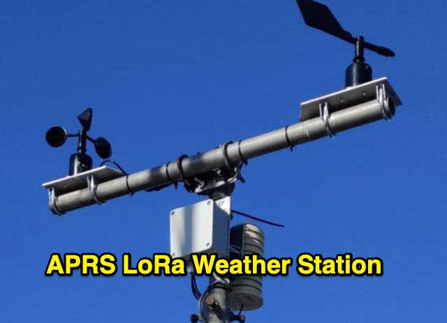 The weather station described here uses a TTGO v3 1.6.2 module and various sensors. It displays the data on an OLED screen and transmits them among a choice of protocols to the APRS, APRS-IS, Wunderground servers or via an MQTT broker. APRS data is transmitted on 433.775 MHz (can be changed) using the LoRa protocol. APRS beacons picked up by iGate gateways are then transmitted to APRS servers.
 -
 This project involves constructing a dual-band Moxon antenna, optimized for ham radio enthusiasts, with functionality on both the 10-meter and 6-meter bands. The antenna is designed to operate using a single 50-ohm feedpoint, acting as a mini-beam on 28 MHz (10 meters) and as a 2-element Yagi on 50 MHz (6 meters). Performance-wise, it offers a 4.0 dBd gain on 10 meters and 4.3 dBd on 6 meters, with impressive front-to-back ratios of 30 dB and 11 dB, respectively. Builders like Aleks (S54S) and Marcio (PY2OK) have successfully brought this design to life using the provided specifications. Aleks noted that bending the corners of the structure proved especially useful during assembly. The project comes with a detailed parts list, highlighting the use of aluminum tubes with different diameters and lengths to form essential components like the reflectors and radiators. For those looking to fine-tune the antenna, adjustments can be made by altering the length of certain parts that fit into larger tubes. The feeding system is equipped with a balun to accommodate different power levels, making the design versatile enough to handle outputs of either 300 watts or 1 kilowatt.
 -
 The 222 MHz Transverter project, based on Zack Lau's (W1VT) original July 1993 QEX magazine design, provides an IF of 28 MHz for both transmit and receive paths. Rick Bandla (VE3CVG) contributed supplemental notes and construction details, including modifications to achieve 10 mW output power from an initial 4 mW PEP. The design incorporates three distinct boards: a Local Oscillator (LO), a Transmitter (Tx), and a Receiver (Rx), with an estimated parts cost of just over $150 CDN, significantly less than commercial kits. Construction involves both through-hole and surface-mount components, with specific guidance on mounting MAV and MAR devices, grounding techniques, and component selection. The project details include parts lists, schematics for the LO, Tx, and Rx, and board layouts. Troubleshooting advice emphasizes sequential testing, starting with the LO, then Tx, and finally Rx, using a 194 MHz and 222.100 MHz capable FM handheld for signal tracing. Further enhancements are discussed, such as an optional Tx driver stage to boost output to 100 mW and the potential modification of a Motorola Maxor 80 PA for 222 MHz SSB/CW operation. The resource also covers practical aspects like power attenuation pads for IF radios (e.g., FT817) and considerations for enclosure design, including repurposing a Maxor 80 case. Performance reports indicate successful 70 km contacts with only 4 mW output.
 -
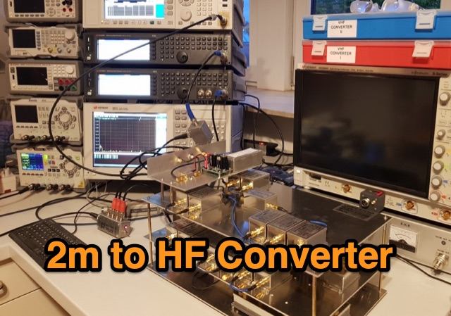 Ulrich L. Rohde N1UL conceived an outstanding 2m to HF receiving converter with specific requirements, including 144-148MHz to 28-32MHz coverage, low noise, high IP3, and a unique modular design. The design decisions emphasize modularity, absence of preselection, stability, and a passive mixer, showcasing Rohde's distinctive approach.
 -
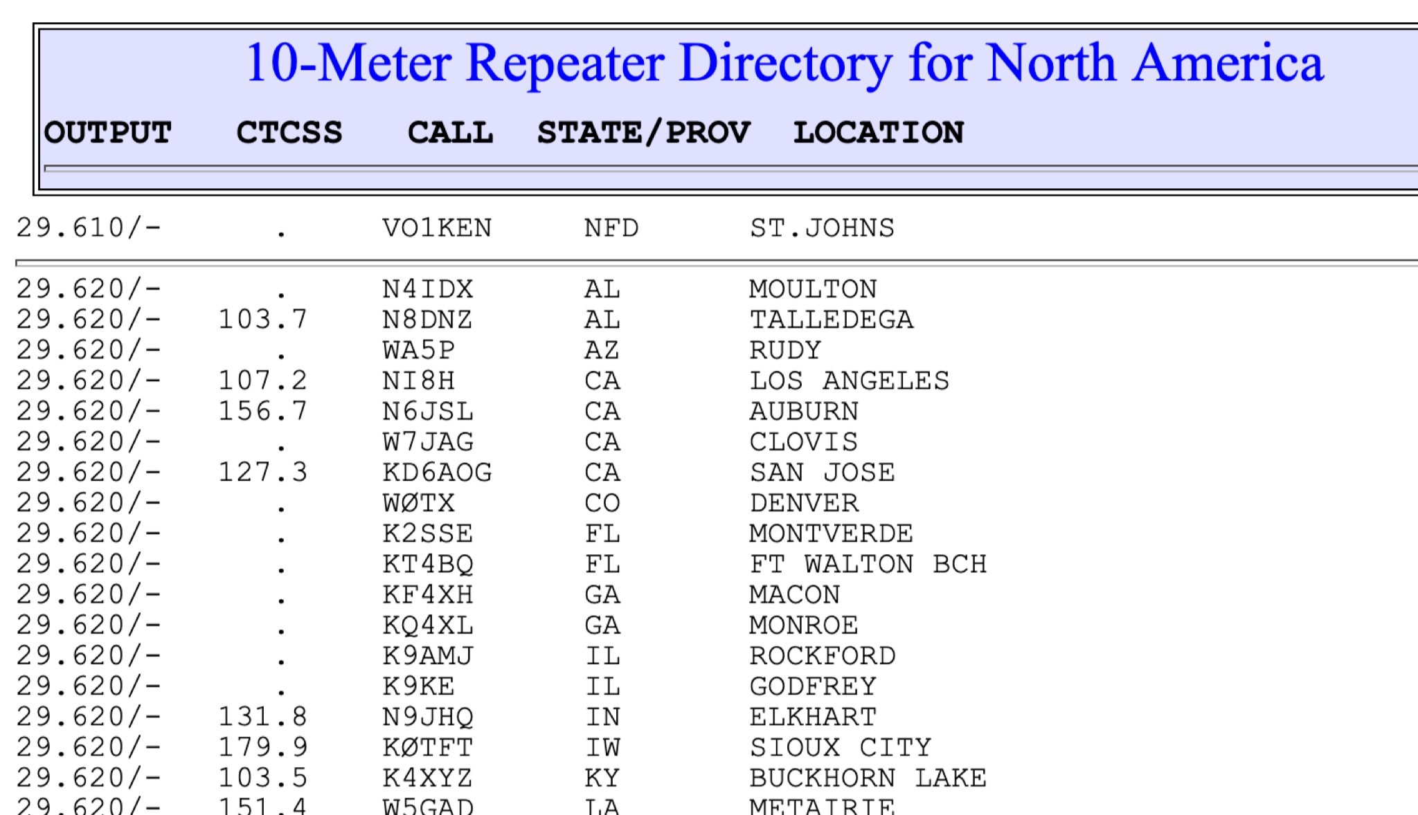 This page show a list of repeaters in north america transmitting from 28 MHz to 29 MHz. The most of them are in the 29.620 to 29.700 frequency range. Some repeaters may be active and on the air while others may not
 -
 The Pikes Peak Radio Amateur Association (PPRAA) serves as an ARRL Special Service Club, providing a calendar of events and activities for its members and the wider amateur radio community. The resource details upcoming events such as the USS Pueblo Memorial Museum Ships Weekend activations, a Cubical Quad Antenna Workshop, LARCFest, and various hamfests including Dayton Hamvention and Duke City Hamfest. It also lists on-air activities like a FreeDV digital voice mode event on 10 meters, a Black Friday Simplex Event on 2M and 70cm, and a 10m event for Technician class operators, emphasizing SSB privileges from 28.300 to 28.500 MHz. The PPRAA's event schedule includes educational opportunities like a Technician Class and a Soldering Workshop, alongside social gatherings such as the PPRAA Picnic and Car Show. Past event summaries highlight successful activities like the 2024 Megafest Raffle, Winter Field Day, and multiple fox hunts utilizing frequencies like 147.420, 147.480, and 147.540 MHz. The club actively supports POTA activations, exemplified by their AF0S park activation at Cheyenne Mountain State Park, and participates in historical commemorations like the USS Pueblo Memorial operations, demonstrating a broad engagement across various amateur radio facets.
 -
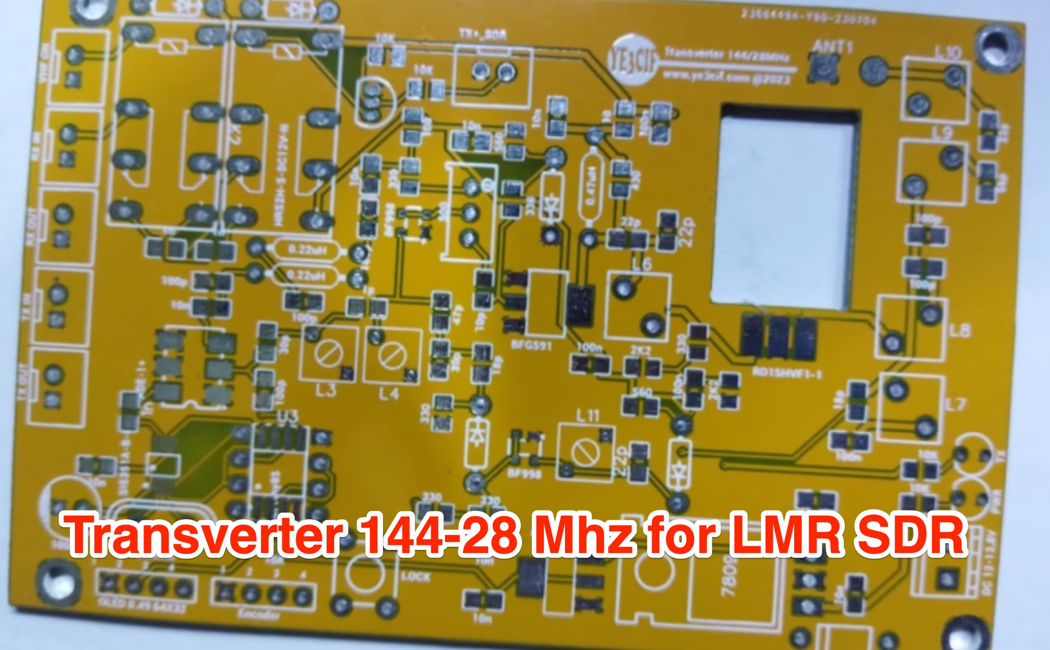 Learn how to build a VHF 144MHz transverter connected to an LMR SDR radio using easily accessible components. The transverter works by mixing the 144Mhz input frequency with a 116 MHz local oscillator frequency. Explore the challenges of finding a 116 MHz crystal and the solution of using a programmable Si5351A oscillator. Follow the provided schematic for the RX and TX sections. The transverter design is still a work in progress, with ongoing trials to achieve optimal results.
 -
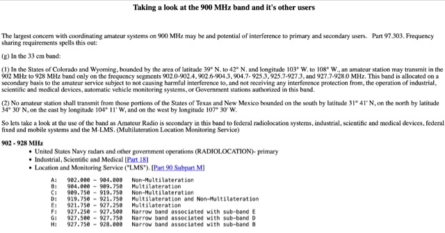 Use of the band as Amateur Radio is secondary in this band to federal radiolocation systems, industrial, scientific and medical devices, federal fixed and mobile systems and the M-LMS. Bandplans for hams. Allocation in 902 - 928 MHz
 -
 A versatile digital VFO design utilizing the Silicon Labs Si5351a oscillator chip and Nokia 5110/3310 graphics LCD display, operating from 1-160MHz with dual VFO capability. This microcontroller-based system, powered by an ATmega328 processor, features rotary encoder tuning, selectable step sizes, RIT control, and comprehensive band memory functions. Drawing less than 40mA at 3.3V, it significantly improves upon previous DDS designs' power consumption while offering advanced features like S-meter display, VFO lock, and programmable BFO/CIO offsets. The design achieves flexible functionality through simple hardware implementation and efficient software architecture, making it particularly suitable for QRP and portable amateur radio applications.
 -
 The RXC70/10 is a sensitive 70 MHz to 10-meterband converter using the Philips SA602 mixer IC. It operates with high stability and low noise, converting 70–72 MHz signals to 28–30 MHz for general coverage receivers. The compact, low-power design (15mA) supports various modulations and uses. Its versatility makes it suitable for amateur radio applications with proper tuning and antenna setup.
 -
 Demonstrates the construction of an active loop converter specifically designed for the Low Frequency (LF) bands, addressing common localized noise interference in LF reception. The design integrates a sharply tuned circuit and a tuned loop antenna, utilizing the loop as the sole tuned inductive element. By applying positive feedback, the converter significantly increases the loop's effective Q, achieving factors between 1000 and 2000, which sharpens tuning and reduces noise. The circuit employs an _NE602_ mixer stage, feeding its output to an HF receiver, with a crystal-locked local oscillator at 4 MHz. A 20-turn, 0.8-meter square loop antenna with 500 uH inductance is detailed, connected via 2 meters of figure 8 flex cable. The converter offers three selectable frequency bands: 195-490 kHz, 150-220 kHz (including the New Zealand amateur band), and 128-160 kHz (covering the European amateur band). Performance measurements indicate an effective 3dB bandwidth of approximately 100 to 200 hertz at 200 kHz. The article provides insights into component selection, including an _LF353_ op-amp and a trifilar wound transformer on a ferrite core. Sensitivity figures are presented, showing 7.5 uV of converted output per 1 uV/meter signal strength into a 50-ohm load, or 37.5 uV into an _FRG7_ receiver, highlighting its capability to extract weak signals from noise.
 -
 The W6PQL 23cm Beacon Project describes a **1296 MHz** beacon designed for microwave propagation studies and equipment testing, capable of 30 watts output. It utilizes a PIC 16F628A microcontroller to generate CW and FSK keying for a crystal oscillator, followed by a series of frequency doublers and triplers to reach the target frequency. The final power amplification stage employs a Mitsubishi M57762 module, providing a robust 10-watt RF output. The design emphasizes stability and reliability for continuous operation, with the microcontroller code, written in assembly, provided for customization of the beacon's callsign and message. Originally located in CM97am and aimed at 140 true, the beacon used four 4-foot Yagis stacked vertically for a total ERP of 3kW. The article includes schematics, parts lists, and construction notes to guide builders, along with antenna pattern measurements. Although the beacon itself is no longer in service as of August 2010, the detailed documentation remains a valuable reference for amateur radio operators interested in building similar **microwave** projects or understanding beacon operation.
 -
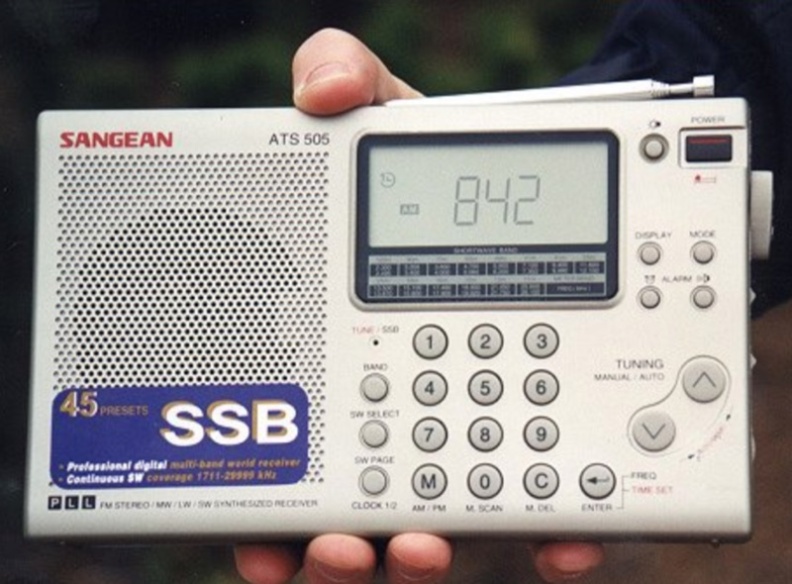 Examines the Sangean ATS-505 portable receiver, a unit introduced in March 2000, providing an in-depth analysis of its capabilities. The review details critical specifications such as its 6 Volt DC power requirement, utilizing 4 AA batteries, and its physical dimensions of 128 x 214 x 39 mm, weighing 840 g without power cells. Frequency coverage spans **LW** from 153-279 kHz, **MW** from 520-1710 kHz, **SW** from 1711-29999 kHz, and FM from 87.5-108 MHz, making it a versatile listener for various broadcast types. Key features highlighted include a backlit display for low-light operation, 45 memory presets for quick access to favorite stations, and the inclusion of Single Sideband (SSB) mode, which is crucial for serious shortwave listening and utility monitoring. The review also draws technical comparisons with other Sangean models, specifically the ATS-404 and ATS-909, pointing out differences in band coverage and operational features. This independent assessment offers practical insights into the ATS-505's performance, helping enthusiasts understand its place within the portable receiver market.
 -
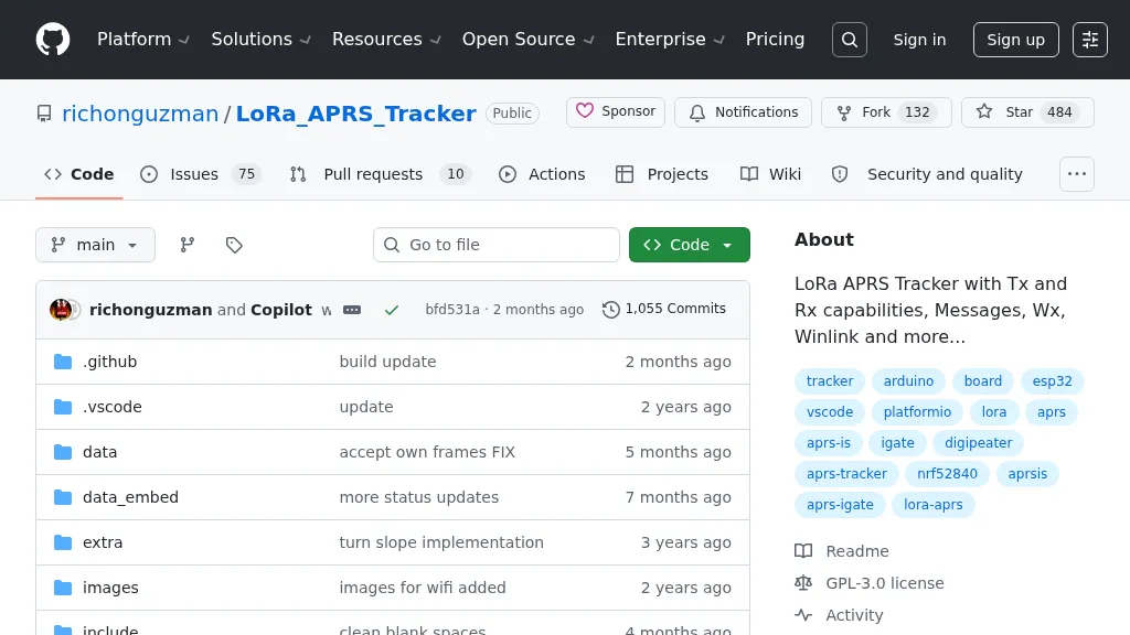 Demonstrates a LoRa APRS Tracker project featuring a comprehensive menu system for message management, weather requests, and monitoring nearby trackers. The device supports adjustable display eco mode and screen brightness, optimizing power consumption by dynamically changing processor speed from 240MHz to 80MHz. GPS beacons are encoded for efficient RF transmission, and an OLED screen displays altitude, speed, course, _BME280_ weather data, or new message counts, along with recently heard stations. Bluetooth connectivity enables operation as a TNC with Android (APRSdroid) or iPhone (APRS.fi app), providing LED and sound notifications for transmissions and received messages. The integrated BME280 module facilitates weather data display and transmission, with Winlink mail support via _APRSLink_. The tracker can switch between **three major LoRa APRS frequencies** worldwide, offering versatile global operation.
 -
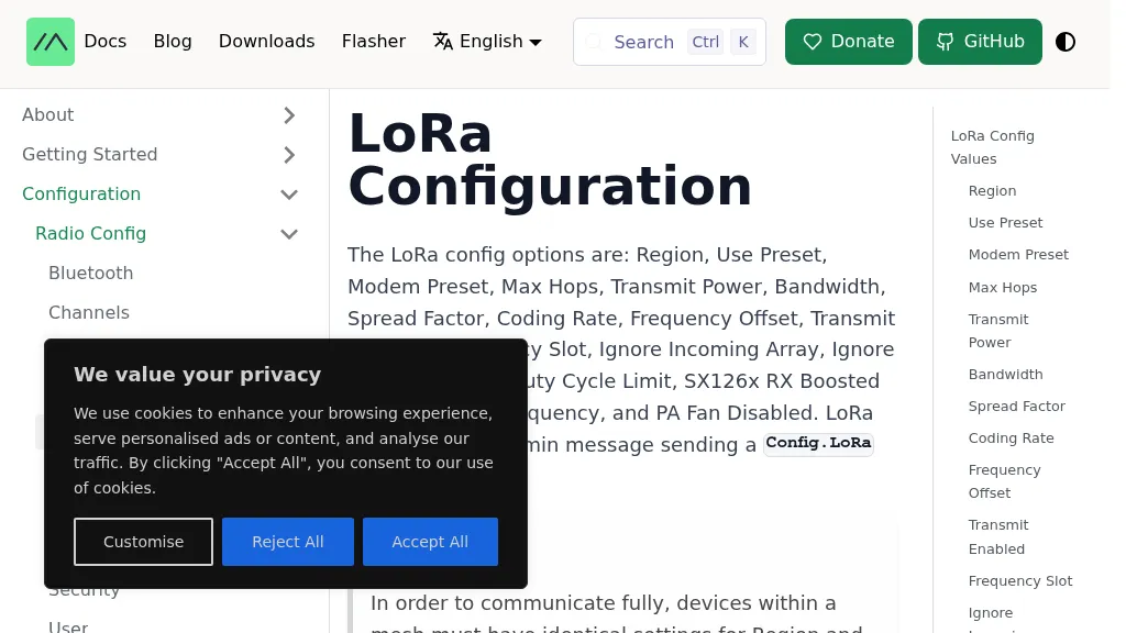 The Meshtastic documentation outlines critical LoRa configuration parameters for node operation, emphasizing regulatory compliance. It details settings such as Region, Modem Preset, Max Hops, Transmit Power, Bandwidth, Spread Factor, Coding Rate, and Frequency Offset. A comprehensive table provides region codes, frequency ranges (e.g., US **902.0 - 928.0 MHz**), duty cycles, and power limits (e.g., EU_433 **12 dBm**) for numerous countries, including the US, EU, China, and Japan, alongside a 2.4 GHz band option. It explicitly states that devices within a mesh must share identical _Region_ and _Modem Preset_ settings for full communication. Modem Presets, like _LONG_FAST_ (the default), optimize for either speed or range, directly impacting network congestion and message delivery delay. For instance, SHORT_TURBO offers the fastest speed and shortest range, while VERY_LONG_SLOW provides the longest range but is less reliable for mesh formation. The document also highlights specific duty cycle limitations, such as the 10% hourly limit for EU_433 and EU_868 regions, and provides command-line interface (CLI) examples for configuring these parameters.