Search results
Query: angle
Links: 130 | Categories: 0
-
 The Tri-pole antenna, a clever modification of a standard dipole, allows for dual-band operation by integrating a third element. This design effectively shortens the overall dipole length by 10 to 20 percent, simplifying antenna rotation and offering a compact footprint. KK4OBI's article delves into the operational principles, using a 6 and 10-meter Tri-pole as a primary example, and provides comprehensive instructions for constructing any Tri-pole antenna within the 6 to 15-meter range. Key to the Tri-pole's performance is its off-center feed, necessitating a common mode choke at the feed point for optimal tuning and reduced noise. The author outlines a methodical approach to determining element dimensions, starting with a vertical element frequency calculated as 0.47 times the sum of the desired upper and lower band frequencies. This calculation, along with K-values derived from trend lines, guides the initial lengths for the horizontal arms, demonstrating how a 10m-6m Tri-pole can achieve a total horizontal length 78% shorter than a conventional 10-meter dipole. Tuning and balancing are critical, with the article detailing adjustments to arm lengths and the vertical element to achieve balanced SWR values, as validated through 4NEC2 simulations. Radiation patterns are analyzed at various elevations, showing gains around 5.7 dBi and favorable take-off angles for DX contacts. Construction details specify aluminum tubing dimensions, U-bolts, and an SO-239 connector, emphasizing the importance of a ferrite-based choke for wideband operation.
 -
 A quarter wave vertical omni-directional antenna for 7 MHz. Formulas for dimensions in feet and meters are provided. Ideal radial angle is between 35° and 45°. Velocity factor (Vf) varies based on coax type.
 -
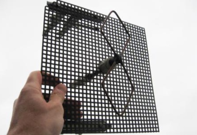
 The DIY 137 MHz WX SAT V-dipole antenna project details the construction of a specialized antenna for receiving weather satellite transmissions. It provides specific dimensions for the dipole elements, designed for optimal reception around the 137 MHz band, which is commonly used by NOAA and Meteor weather satellites. The resource outlines the materials required, such as aluminum tubing for elements and PVC for the support structure, along with the necessary coaxial cable and connectors. The article presents a clear, step-by-step assembly process, including how to form the V-shape and connect the feedline. It emphasizes practical considerations for mounting and weatherproofing the antenna for outdoor deployment. The design focuses on simplicity and effectiveness for amateur radio operators interested in satellite imagery. Key aspects include the precise angle of the V-dipole and the lengths of the radiating elements, which are critical for achieving the desired circular polarization response for satellite signals. The resource includes photographic documentation of the construction phases and the final mounted antenna.
 -
 This page delves into the Inverted V antenna, a source of myths among ham radio operators. The author explores the behavior of this antenna type with a focus on a 20m half-wave dipole positioned 10m above the ground. From Pythagoras to high school math, the article simplifies the calculation of dimensions and angles for setting up an Inverted V antenna. It includes a spreadsheet for calculating hypotenuse length and angles, crucial for antenna setup. Additionally, it provides insight into the radiation pattern of a 'flat' half-wave dipole at 10m height. Useful for hams planning to optimize their antenna setup. In Norwegian.
 -
 This article provides a detailed guide on how to build a no holes roof mount for ham radio antennas. The author shares their design that can hold 2 masts and offers tips on installation. The mount is versatile and can handle small 144 Mhz or 432 Mhz beams, as well as small verticals. With adjustable angles and spacing, the mount can be customized to fit different roof types. Additionally, the author suggests affordable options for obtaining Dish antenna mounts. Overall, this DIY project offers a cost-effective solution for ham radio operators looking to mount antennas on their roofs.
 -
 Mounting on roof at the right ground level can greately impact on antenna performances because will affect the radiated angle of energy.
 -
 An Inverted-L with its long leg sloping to the ground. It will still work very good, even if the horizontal wire has to be sloped diagonally to the ground, as long as you have enough horizontal space to keep it at about a 45 degree angle or more from the pole.
 -
 An easy to build double quad antenna that can be used as an antenna for beginners, it features a wide angle providing a generous alignment.
 -
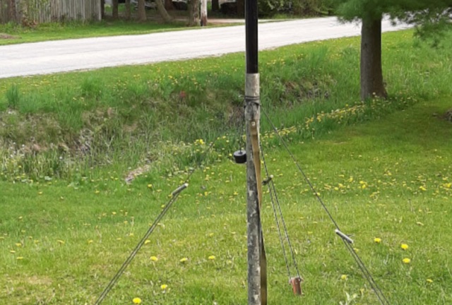 Supporting a telescopic fiberglass antenna pole for ham radio operation. Rather than cumbersome methods like using angle iron or PVC pipes, author employs lightweight tent stakes, toggles, and paracord to secure the pole effectively. With careful knot tying and simple materials, he ensures rapid deployment and stability even in windy conditions, offering a practical solution for outdoor antenna setups.
 -
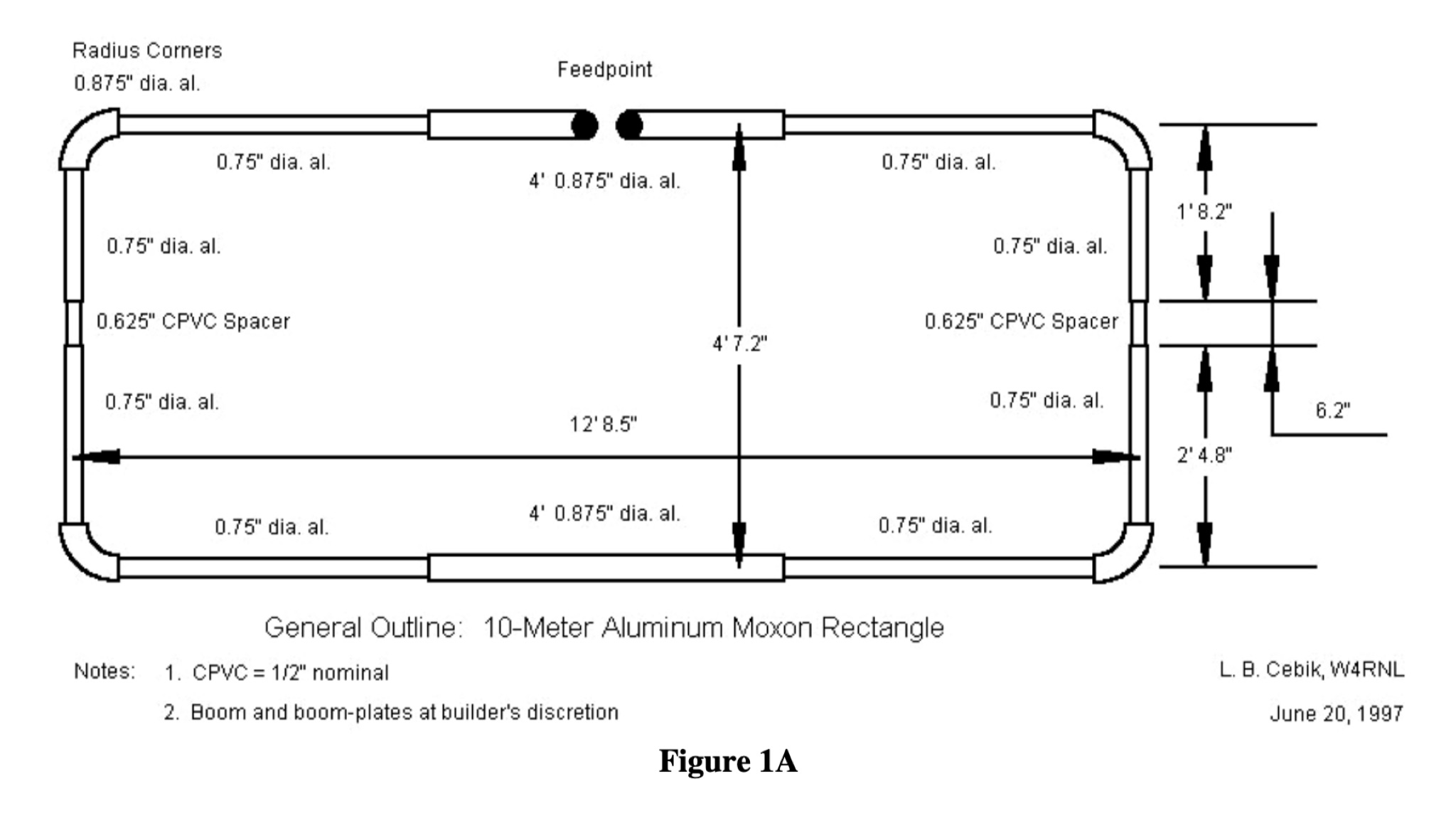 This PDF document provides a comprehensive guide on building and using the Moxon Rectangle antenna design for hams. It covers the construction, setup, and tuning of this directional antenna, offering practical advice and tips for amateur radio operators looking to improve their signal reception and transmission capabilities. The guide includes diagrams, measurements, and step-by-step instructions to help hams successfully implement the Moxon Rectangle design for their radio communication needs.
 -
 In this article the author describes his personal experience on some antennas for 50 MHz he tested on the field, the six meter Dipole, Vertical, Moxon, a 3 element Yagi and an Omniangle antenna.
 -
 The author wants a compact, switchable antenna for 40-meter ham radio. They compare 3 designs: rectangle, short-tipped W6NL, and T-hat. All work well electrically, but mechanics matter for a large antenna. The rectangle needs strong support, while the T-hat is sturdier with slightly longer elements. The T-hat design wins for now, but the author will focus on its mechanical details next.
 -
 This study details a reception comparison between vertical and horizontal active loop antennas, specifically two identical _Wellgood active loop antennas_, on various HF bands. The experiment, conducted in a densely populated QRM-prone area, monitored FT8 signals over a 24-hour period using two identical receivers. The methodology involved direct comparison of signal reception across the HF spectrum, aiming to identify performance differences based on antenna orientation. The results indicate that vertical loops demonstrated superior performance on higher bands (10m, 15m, 20m), while horizontal loops excelled on lower bands (30m, 40m, 160m), particularly for receiving long-distance (DX) signals. The horizontal loop's advantage on lower bands is attributed to potentially better low-angle performance and reduced sensitivity to man-made noise, yielding a **2-3 S-unit** improvement on 160m. The study provides practical insights for optimizing antenna placement in challenging urban environments, noting that the horizontal loop consistently showed a **10-15 dB** signal-to-noise ratio improvement on lower bands.
 -
 The article describes the construction of a Lindenblad antenna, which is well-suited for receiving signals from low-orbiting weather satellites. The key points are: The Lindenblad antenna has an omnidirectional horizontal radiation pattern and is optimized for low to medium elevation angles, making it ideal for tracking passing satellites near the horizon. It is designed to receive circular polarization, which is common for weather satellite signals. The antenna is constructed using 4 folded dipole elements arranged on a cross-shaped frame. The necessary materials include a plastic junction box, PVC tubing, and aluminum rods to form the dipole elements. The article provides detailed instructions for preparing the components, assembling the dipoles, and connecting the feed lines to create the complete antenna. The completed antenna can be mounted on a vertical support, with the dipole elements angled at 30 degrees from horizontal, to optimize reception of the passing satellites. The author notes that the design was originally published in a now-defunct magazine, Meteo Satellite Inf", in 1993
 -
 Over 1000 _Elecraft_ KX2 owners have benefited from the Kx22 Heatsink, experiencing cooler rig temperatures and higher output powers. PAE manufactures these heatsinks, along with AC power supplies for HF transceivers, remote power relays, and Ethernet relays, with all machined products manufactured in the **USA**. PAE distributes _Fair-Rite_ Mix 31 ferrite snap-it cores and toroid cores, essential for RFI suppression and impedance matching in amateur radio setups. The product line also includes commercial monitoring antennas, UQUI transformers, ULP AC power filters, and 3M conductive adhesive copper tape, catering to various station build-out and maintenance needs. The AM1 Portable Antenna Mount System and its AM1-VA Multi-Angle Adapter offer flexible antenna deployment options. PAE ensures careful packing of fragile ferrite products, with shipping cost adjustments communicated post-order for larger, heavier combinations to guarantee safe delivery.
 -
 SWR Magazine is free montlhy ham radio online magazine published in English and Spanish. SWR Magazine presents a mix of analysis, hands-on experience, and technical insight for ham radio operators. Covering global radio trends, technical topics like antenna takeoff angle, operating practices outside the shack, reviews of radios, propagation. Explore innovative antennas, digital modes like RTTY, and historical radio origins. This issue bridges the past, present, and future of amateur radio, inviting readers to not just read, but experience and experiment with the content.
 -
 A vertical delta loop is a practical antenna for low bands, popular for its simple design requiring just one support. Its shape, an equilateral triangle in free space, yields optimal gain and radiation resistance. Deviating from this shape lowers performance. The delta loop can be polarized either horizontally or vertically based on the feed point location. In vertical polarization, it acts as two quarter-wave verticals with the baseline feeding one side. This design minimizes radiation from the baseline while maintaining effective operation.
 -
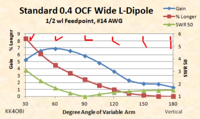 This page is a discussion about impedance matching by Off Center Fed dipoles in the Wide L-form. When a vertical or horizontal dipole is bent into a 90 degree L-form, the impedance drops about half.
 -
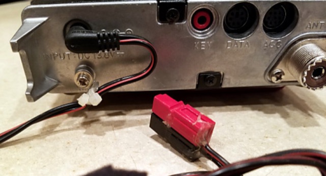 Attach a small right angle lug to the ground screw located in the rear of the FT-817 in order to make a more robust and stable power connection
 -
 This article focus on the radiation angle of vertical antennas and the fundamentals of electromagnetic wave propagation. The calculation of antenna length at 145 MHz is followed by an explanation of electromagnetic wave speed and the link between wavelength, frequency, and velocity. Author discusses the 5/8th wave vertical antenna, namely its performance and the influence of radiation angle on signal transmission. Figures and analogies demonstrate how different antenna types produce distinct radiation patterns. This highlights the importance of selecting the right antenna for a certain purpose, such as local traffic or dxing. The article discusses a variety of factors that affect antenna performance, including SWR, propagation conditions, and equipment dependability
 -
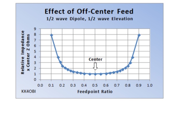 The behavior of a straight dipole and its L-form is examined in terms of impedance and SWR. By adjusting the feed point or bending angle, impedance variation is observed. Impedance shifts symmetrically as the feed point deviates, leading to recommendations for optimal ratios. Model simulations aid in understanding and fine-tuning, crucial for achieving a 50 Ohm match. Practical tuning guidelines ensure efficient antenna performance.
 -
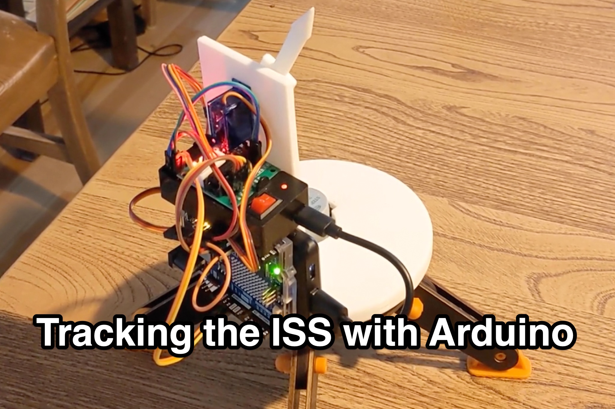 Learn how to hack an IR turret to track the International Space Station (ISS) as it passes overhead. Discover the basics of the ISS and how to use simple tools to point an arrow at the ISS without looking at a phone. Find out how to calculate the azimuth and elevation angles to locate the ISS in the sky and enjoy watching this habitable space craft orbit the earth at a speed of 28,000 km/h. Take your hobby to the next level by bouncing radio signals off the ISS or even talking to the astronauts on board. Turn stargazing into an interactive and educational experience with this fun and practical project.
 -
 Delta loop antennas, particularly the 30 meter variant, offer unique advantages in terms of vertical polarization and omni-directional coverage. The construction process detailed by VE3VN highlights common mechanical and electrical challenges faced by amateur radio operators. Key design considerations include minimizing interaction with existing contest band antennas, achieving low elevation angles for DX chasing, and ensuring the antenna remains off the ground for agricultural clearance. The article provides specific measurements, such as the loop's height and feed point impedance, which are critical for optimizing performance. The use of NEC modeling software illustrates the importance of accurate resonance calculations, revealing how proximity to the tower affects both pattern and impedance. This practical account serves as a resource for hams looking to build effective antennas while navigating typical construction hurdles.
 -
 The ICOM IC-705, a popular QRP transceiver for portable operations, often presents unique challenges for field deployment. This resource details practical solutions for common portable setup issues, particularly for _Parks on the Air_ (POTA) activations. It describes a custom bracket for connecting antennas to the IC-705 through a backpack's antenna flap, utilizing a BNC female-to-female chassis mount connector to mitigate cable tangles. The author shares experiences with a DIY magnetic loop antenna, noting its ease of tuning with the IC-705 and successful CW contacts on 40 and 20 meters over distances exceeding **1000 miles**. Another modification presented is a strain relief solution for the microphone cord, replacing the standard spring clip with an easier-to-attach method. The page also mentions using a _Wolf River Parks antenna_ for POTA activations and references the QRPGuys DS-1 antenna as another portable option. Firmware updates and integration with an LDG Z11-Pro II auto-tuner are also discussed.
 -
 A full-wave delta loop antenna, approximately 141 feet in total wire length for the 40-meter band, offers a low angle of radiation, which is highly advantageous for DX operations. This design, optimized for both 30m and 40m, leverages a specific circumference calculation of 1005/F, ensuring resonance on both bands through a simple switching mechanism. The antenna's configuration enhances long-distance communication, making it a practical choice for hams with limited space. The resource details the construction process, including the use of a _Ceramic Knife Switch_ for band selection and an _RG-11_ matching section to achieve optimal impedance. It outlines the precise loop lengths required for each band, along with tuning secrets to ensure efficient operation. Requiring a minimum height of 12 feet, this antenna can be supported by a single mast or tree limb, making it suitable for suburban installations where stealth or space constraints are a factor.
 -
 This paper presents an 80 meter wire 3-element beam antenna in an inverted-V configuration, designed for limited-height towers. Using EZNEC modeling, the antenna features a central parasitic reflector and two switchable driven elements at each end, enabling NE/SW coverage without moving parts or networks. Element lengths are optimized for SSB (3.8 MHz) and CW (3.5 MHz) operation, with a 50 Ω feed and rope-supported boom. The design delivers high gain, effective takeoff angles, and excellent reception, confirmed in real-world DX contest operation. Its simplicity, reliability, and ease of construction make it ideal for operators seeking performance without complex matching systems.
 -
 Operating amateur radio satellites presents unique challenges, particularly concerning antenna design and signal propagation. Juan Antonio Fernández Montaña, EA4CYQ, recounts his three-year journey into satellite communication, starting with initial guidance from EB4DKA. His early experiments involved a portable 1/4 wave VHF antenna with four 1/4 wave ground planes, designed for hand-held use to adjust polarity. This setup, paired with an FT-3000M transceiver, allowed full-duplex operation on **VHF** transmit and **UHF** receive, proving effective for early contacts on satellites like AO27, UO14, and SO35. EA4CYQ's experience highlights the critical role of coaxial cable loss and antenna polarization. After encountering significant signal degradation with longer RG213 runs, he experimented with a 1/2 inch commercial cable, noting improved reception but persistent fading due to varying satellite polarities. This led to the construction of an **Eggbeater II** antenna, an omnidirectional UHF design offering horizontal polarization at the horizon and circular right polarization at higher elevation angles. Subsequent modifications resulted in the directional **TPM2** antenna, which provided sufficient gain for LEO satellites with a wide 30-degree lobe, enabling consistent contacts from his home station. The article concludes with practical insights on the performance of the Eggbeater II for both UHF and VHF, and the TPM2 for UHF, emphasizing their utility for portable and fixed operations. EA4CYQ's journey underscores the iterative process of antenna development and the importance of adapting designs to overcome real-world propagation challenges in satellite communications.
 -
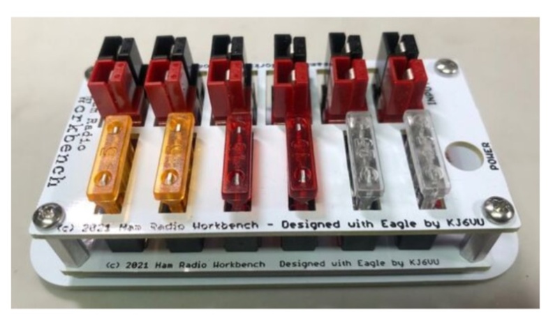 The **5-Port 12 Volt DC Power Strip Kit (Rev 4)** offers a practical solution for managing shack power distribution, providing one input and five fused outputs. All connections utilize the ubiquitous Anderson PowerPole connectors, a standard for many amateur radio operators, ensuring a clean, organized, and safe way to power multiple 12 VDC transceivers and accessories from a single source. This design mitigates the common issue of tangled wires and overloaded connections in a typical ham shack. Rated for a maximum current of 20 Amps at 12 VDC, the strip incorporates an integrated LED to indicate when external power is applied. Each output is individually fused, a critical safety feature that protects connected equipment from overcurrent conditions without affecting other devices on the strip. This level of protection is essential for preserving sensitive radio gear during operation. Assembly requires basic soldering skills and hand tools, with a high-power soldering iron and wide chisel tip specifically recommended for best results. The kit's compact dimensions of 4.13" x 1.78" allow for flexible mounting via screw holes, making it suitable for various shack configurations and portable operations.
 -
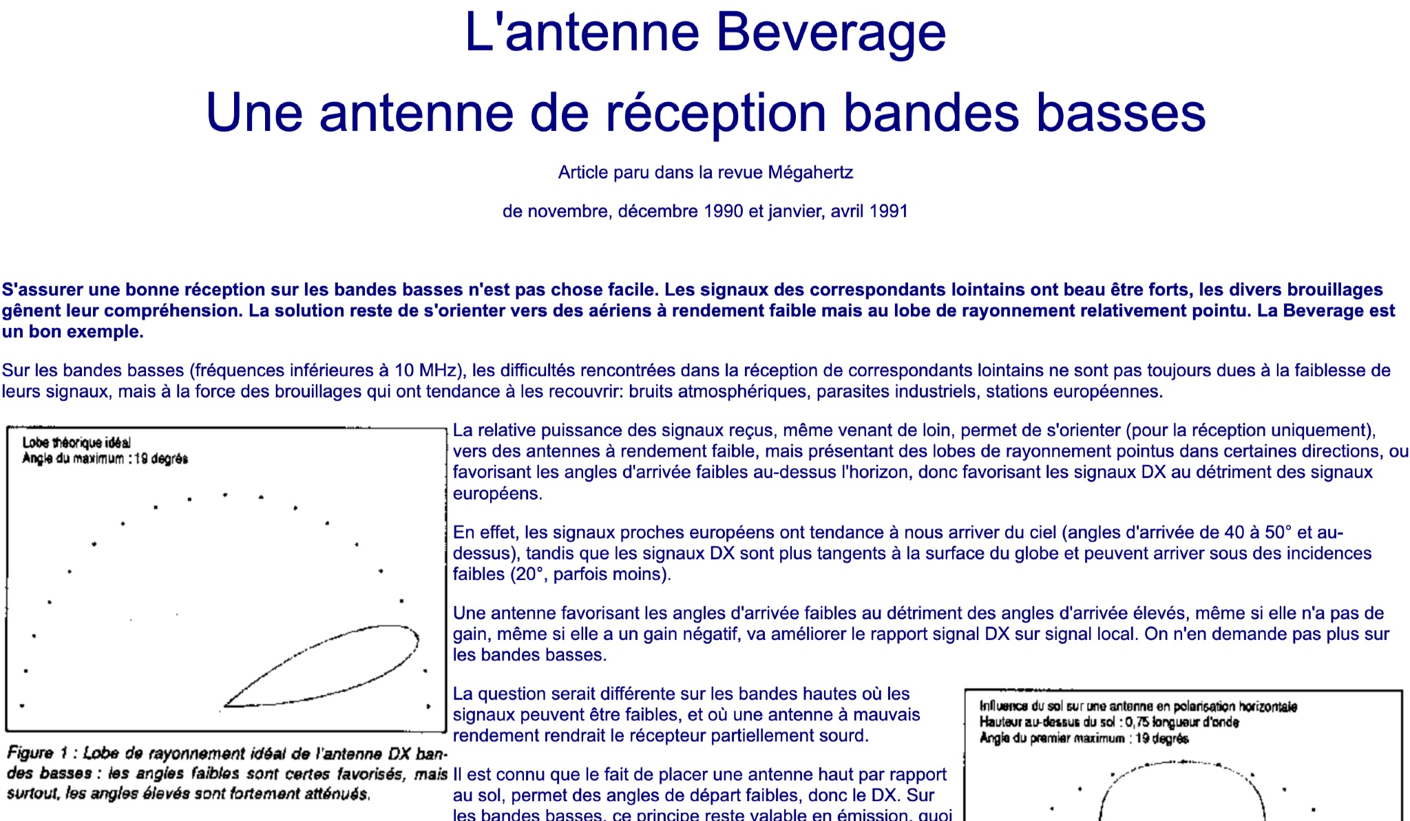 This article discusses the Beverage antenna, a reception antenna for low bands, originally published in the Megahertz magazine between November 1990 and April 1991. It explains the challenges faced in receiving signals on low bands due to interference and how the Beverage antenna's directional radiation pattern can help improve reception of distant stations. The article highlights the importance of choosing antennas with low efficiency but sharp radiation lobes for better DX signal reception. It also compares the reception characteristics of signals from European stations versus DX stations, emphasizing the benefits of antennas favoring low arrival angles for DX signals on low bands.
 -
 The 4m Slim Jim antenna project provides a construction guide for a low-cost, high-performance aerial designed specifically for the 70 MHz FM band. This design achieves a 1:1 SWR across the 4m FM band with straightforward adjustment of the feed point, utilizing RG-58 coax. Its low angle of radiation contributes to effective signal propagation. Construction involves using plastic knitting needles as spreaders and a telescopic fishing pole for support, with components secured using two-part epoxy. Annealed bare single-core copper wire forms the radiating element. The setup process includes raising the antenna at least 3 meters above ground for tuning, adjusting the RG-58 feed point for optimal SWR, and then soldering connections. Waterproofing is achieved with yacht varnish. The design emphasizes low wind resistance for durability, making it suitable for exposed outdoor installations. A PDF construction diagram is available to supplement the written instructions.