Search results
Query: how to use an antenna an
Links: 135 | Categories: 0
-
 The mini Radio Solutions miniVNA PRO is the only affordable vector network analyser (VNA) I know of that offers remote wireless operation. This is very interesting because it allows to measure the input impedance of HF antennas installed at height without having to deal with coax cable lengths, baluns nor common mode suppression chokes. However, to render the miniVNA PRO truly field proof, it requires a number of significant modifications.
 -
 This article describes the phases for the construction of a Yagi antenna. The calculations of the parameters are made using 4NEC2 software. This type of antenna is used for transmissions and receptions of electromagnetic waves. The project shown here refers to the frequency of 433.92 MHz.
 -
 When building antennas for the Wifi band (Like the 8dBi omni), a need for an easy way to check the antennas arose. A Voltage Standing Wave Ratio (VSWR) meter useable at the 2.4GHz band is however, hard to find.
 -
 Hamradio_copilot is an open-source tool designed for DXers and contesters who need real-time situational awareness. It is ideal for operators who want to visualize propagation trends instantly rather than scrolling through raw text streams of cluster spots. Rally acting as a copilot for your station, this tool transforms raw data into actionable intelligence. By visualizing Signal-to-Noise Ratios (SNR) across different bands, it helps operators make quick decisions on which band to prioritize or where to point their antennas, effectively showing not just who is on air, but where the propagation is currently open from your location. This is a fantastic information for avid contesters. The software aggregates data from two primary services: - Reverse Beacon Network (RBN) via Telnet. - PSK Reporter via MQTT feeds. It processes this data to generate a comprehensive HTML report featuring SNR heatmaps and statistical breakdowns by ITU Zone. Users can filter data by specific zones or country codes (ADIF), analyze historic time ranges, and optionally integrate solar weather data. The complete source code is available on GitHub, allowing for community customization. It is written in Python and uses SQLite for data management.
 -
 IAT is an excel sheet table evaluate parameters of VHF UHF antennas edited by Vladimir UR5EAZ. The difference between this tool and the existing VE7BQH Antenna Table is the use of G / T and C / N instead of the G / Ta parameter. In this table, Vladimir applies the ITU recommendations to assess the noise properties of a radio receiving system and shows the advantage of the G / T concept over the G / Ta concept when choosing an antenna.
 -
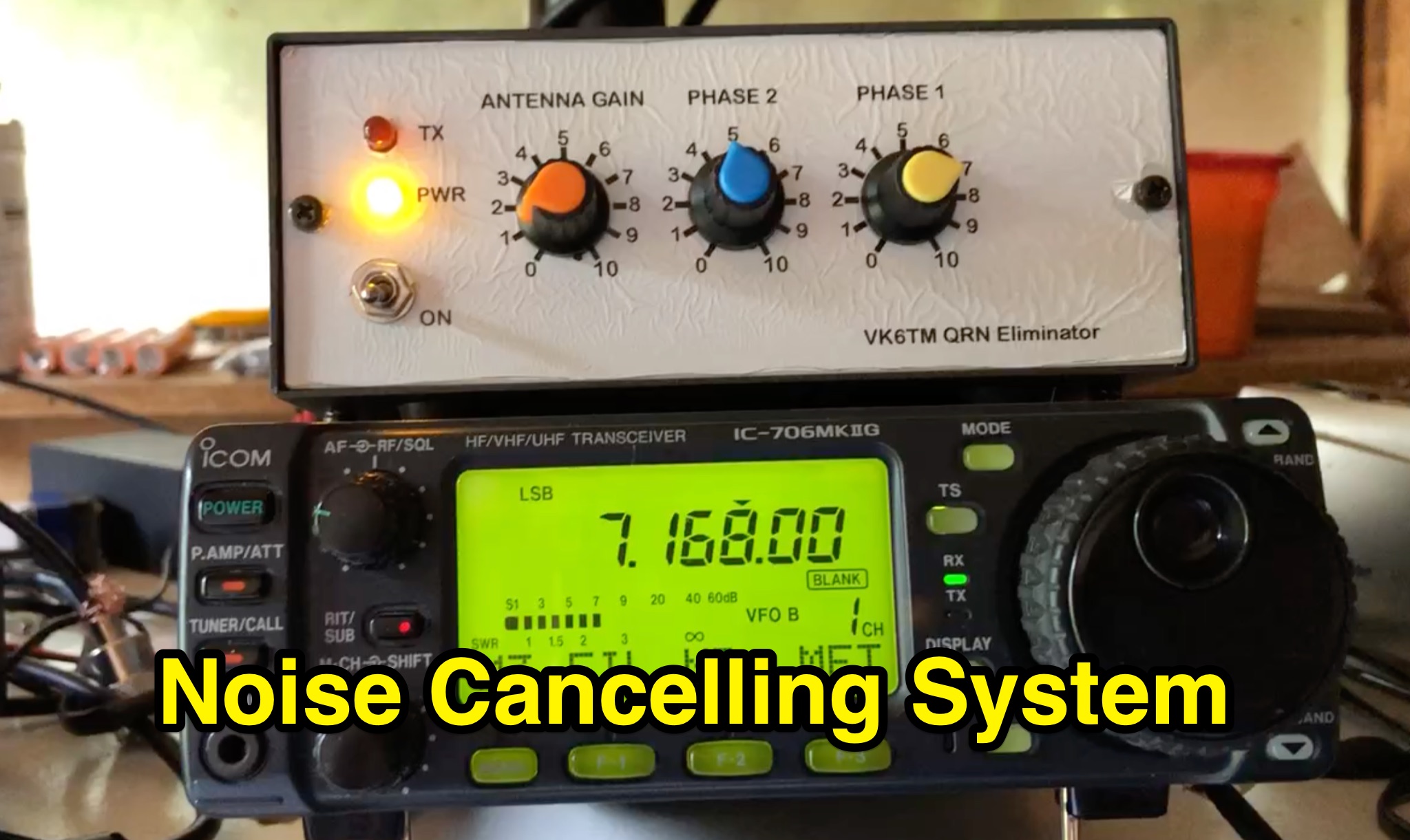 Learn how to improve reception on the hf bands by setting up a noise cancelling system that nulls out local interference. This article describes a system using a 'Main Station Antenna' to receive a wanted signal and associated QRM, and an 'Auxiliary Antenna' to pick up unwanted interference. Gain and phasing controls are used to reduce/remove interference, leaving only the wanted signal. Tips are provided based on the author's personal experience, applicable to commercial noise cancelling products, kit form, or homebrew setups. Discover the importance of configuring the 'Auxiliary Antenna' to optimize your system and improve readability of wanted stations.
 -
 The author shares a unique experiment with a 200ft Grasswire antenna—laying wire directly on the ground. Despite inherent losses, the setup enables successful radio communication with a Kentucky station, highlighting the antenna's practicality for portable use with minimal power.
 -
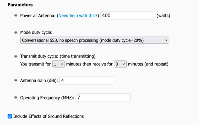 To use the RF Exposure Calculator, fill-in the form with your operating power, antenna gain, and the operating frequency. Depending on how far above ground the RF source is located, you might want to consider ground reflections too.
 -
 A 5/8 λ antenna, often thought to be ideal for all frequencies, has unique characteristics that don't universally apply. First introduced for medium-wave radio, it works optimally at 225° antenna length over ideal ground, yielding high efficiency. However, at VHF and higher frequencies, it offers no advantage over other antennas due to real ground conditions and complex matching requirements. DIY calculators provide only rough estimates, useful as a starting point for simulations, not for precise builds.
 -
 Learn how to build your own QRPGuys DS-1 40-10m short vertical antenna for ham radio operators. This page provides detailed instructions on constructing this antenna, which covers the 40 to 10-meter bands. Whether you're a beginner looking to get started with antenna building or an experienced ham radio operator looking for a new project, this resource is useful for anyone interested in DIY antennas for portable or QRP operations.
 -
 This page allows hams to design a vertical-plane delta-loop antenna for a single amateur HF band in different configurations. By choosing different feed-point positions, operators can observe variations in polarization properties, radiation patterns, and feed-point impedances. Users can generate radiation pattern plots, VSWR charts, antenna current diagrams, and Smith charts for their antennas over various ground types. Through adjusting the antenna's physical dimensions and refreshing the plots, hams can gain insights into the antenna's performance in the field. The page also discusses how elevation radiation patterns may change based on the antenna configuration and feed-point position.
 -
 This blog post by VE3VN discusses the design and performance of a 40-meter reversible Moxon antenna. The antenna provides coverage between southeast to west by default, with the ability to reverse for coverage from east to northwest. The post explains how the antenna performs well in various directions, focusing on the Caribbean, South/Central America, the US, and Europe. Detailed measurements and design considerations are shared, highlighting the accuracy of the model and the critical importance of coil inductance. The post also mentions the use of NEC5 for accurate modeling. Overall, this detailed discussion provides valuable insights for ham radio operators looking to optimize their antenna setup.
 -
 A DIY cantenna can extend your WiFi range by building a 2.4 GHz high-gain antenna using accessible materials. The design, based on waveguide principles, uses a cylindrical tube to capture WiFi signals and can even connect to access points half a mile away in ideal conditions. While the ideal tube diameter was hard to find, a 4-inch aluminum dryer vent was chosen despite theoretical limitations. The cantenna offers a cost-effective, functional boost for your wireless network.
 -
 This comprehensive three-part guide examines baluns (balanced-to-unbalanced devices) and their critical role in ham radio antenna systems. The author explains how baluns prevent common-mode currents on feedlines, which can distort radiation patterns and cause unwanted RF in the shack. Various balun types are analyzed, including coiled coax chokes, ferrite-core designs (W2DU), and toroidal-wound versions (Guanella/Ruthroff). Construction techniques for 1:1, 4:1, 6:1, and 9:1 current baluns are provided with practical guidance on wire selection, winding methods, and ferrite core properties. The article emphasizes that proper balun implementation is essential for optimal antenna performance, especially with directional arrays.
 -
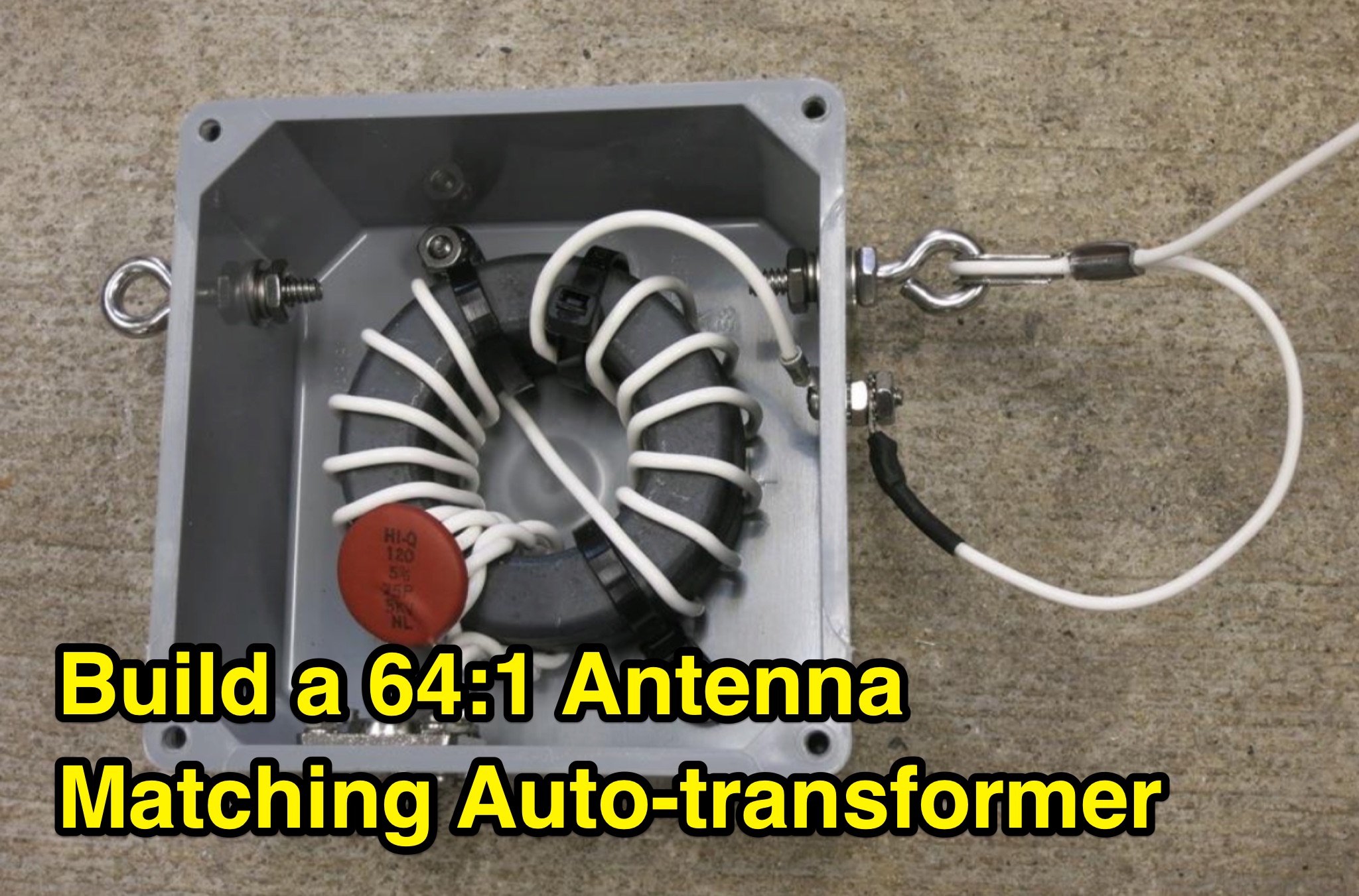 This PDF document provides information on a 64 to 1 antenna matching auto-transformer for ham radio operators. It likely includes details on how to build or use this specific type of antenna matching device, which can be helpful for hams looking to optimize their antenna setup. The document may contain technical specifications, diagrams, and instructions on how to properly implement the auto-transformer. Overall, it serves as a useful resource for hams interested in improving their antenna performance and signal transmission.
 -
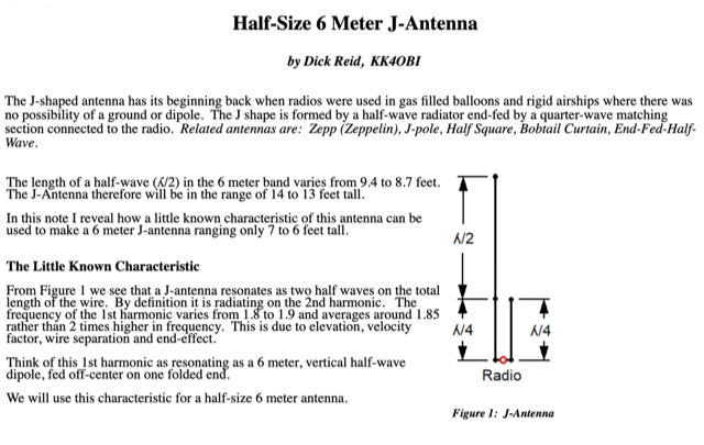 How to use a little known J-antenna characteristic to reduce a conventional 14 foot antenna to 7 feet. Perfect 50 Ohm match, same gain, no radials.
 -
 This page provides guidance on designing an End-Fed Half-Wave (EFHW) or Random-Length antenna for amateur HF bands, such as 80 or 40 meters. The content explains how to optimize the antenna for multi-band use and match it to a 50-ohm system using an unun. Hams can generate radiation patterns, VSWR charts, and antenna current diagrams for their customized antenna designs. Understanding how antenna dimensions affect performance is essential for successful field operations. The page caters to ham radio operators looking to build efficient and effective HF antennas for their stations.
 -
 AutoEZ, Automated use of EZNEC, is an Excel workbook that works alongside EZNEC antenna modeling software version 5.0 or later. With AutoEZ, you can control different aspects of your model using variables and run multiple EZNEC test cases automatically. Formulas in Excel allow you to modify any part of the model. AutoEZ's interface resembles EZNEC's. Enabling macros in Excel might be necessary before using AutoEZ. The program opens various model file formats including EZNEC (.ez), NEC (.nec or .inp), AO and NEC/Wires (.ant), and MMANA-GAL (.maa). You can set the frequency and/or variable values for the test cases to be run through EZNEC. AutoEZ allows you to create animations showcasing how the pattern changes as the model configuration is modified. You can download a fully working, but limited demo copy from this site.
 -
 Learn how to construct a balanced Antenna Tuning Unit (ATU) for your ham radio equipment. Follow the instructions provided by Bengt, SM6APQ, to create a variable capacitor insulated from the ground for additional safety. Discover how to set up the ATU for the 20 to 10m band with proper spacing between coils. Use low power when adjusting the ATU for lowest SWR. Avoid using switches and opt for banana plugs for flexible connections. Visit the Creative Science Centre website for more information and resources on ATU construction.
 -
 This article published on QEX details measurements of tree conductivity and permittivity at HF frequencies, addressing a long-debated topic in amateur radio. N6LF conducted experimental impedance measurements on Douglas fir and maple trees using a vector network analyzer with rings of nails inserted into tree trunks. Results showed that tree conductivity increases with frequency while relative permittivity decreases, similar to soil characteristics. Measured conductivity ranged from 0.06 to 0.4 S/m at 10 MHz, aligning with values used in previous research. These findings validate that NEC modeling can reliably estimate trees' substantial impact on HF antenna performance.
 -
 Learn how to build a simple transmitter called the 'Easy Ten' that can be easily heard at a distance of 10 miles using a random length wire antenna thrown into a tree. This article focuses on working with frequencies in the 3.5 and 7 MHz range without the need for complex setups like coax lines or baluns. The author shares their experience of making contacts across the Pacific Ocean and the United States using just one watt of output power and simple antennas. Discover how to optimize signal output using a homemade level meter made from a DC microameter and a germanium diode.
 -
 The Pikes Peak Radio Amateur Association (PPRAA) serves as an ARRL Special Service Club, providing a calendar of events and activities for its members and the wider amateur radio community. The resource details upcoming events such as the USS Pueblo Memorial Museum Ships Weekend activations, a Cubical Quad Antenna Workshop, LARCFest, and various hamfests including Dayton Hamvention and Duke City Hamfest. It also lists on-air activities like a FreeDV digital voice mode event on 10 meters, a Black Friday Simplex Event on 2M and 70cm, and a 10m event for Technician class operators, emphasizing SSB privileges from 28.300 to 28.500 MHz. The PPRAA's event schedule includes educational opportunities like a Technician Class and a Soldering Workshop, alongside social gatherings such as the PPRAA Picnic and Car Show. Past event summaries highlight successful activities like the 2024 Megafest Raffle, Winter Field Day, and multiple fox hunts utilizing frequencies like 147.420, 147.480, and 147.540 MHz. The club actively supports POTA activations, exemplified by their AF0S park activation at Cheyenne Mountain State Park, and participates in historical commemorations like the USS Pueblo Memorial operations, demonstrating a broad engagement across various amateur radio facets.
 -
 Chavdar Levkov, LZ1AQ, presents an experimental comparison of small wideband magnetic loops, building on his previous work on wideband active small magnetic loop antennas. His research focuses on increasing loop sensitivity by maximizing the short-circuit current, which is directly tied to the "loop factor" M = A/L, where A is the equivalent loop area and L is its inductance. Levkov's methodology involves reducing inductance and increasing area through parallel or coplanar crossed (CC) configurations, comparing these designs against a reference single quad loop of 1 m2 area. Experimental verification included testing three distinct loop types: a simple quad loop, two coplanar crossed (CC) loops, and eight parallel loops, all designed to have a total geometric area of 1 m2. Measurements were conducted at 1.8, 3.5, 7, and 10 MHz using a small transmitter 270 meters away, with a Perseus direct sampling receiver for precise signal level assessment. The results consistently showed that CC loops, particularly Loop 5 (two CC circular loops with 1.44 m2 total area), yielded significantly higher currents, up to 9.1 dB over the reference loop at 3.5 MHz, validating M as a reliable predictor of loop sensitivity. Numerical simulations using MMANA further corroborated the experimental findings, demonstrating an almost perfect correlation between the calculated M factor and the induced loop current for 15 different loop models. Levkov concludes that CC loops offer superior sensitivity for a given loop area, while parallel loops are advantageous for minimizing physical volume. Practical recommendations suggest using loops with an M factor greater than 0.5 uA/pT for quiet rural environments, and he provides a spreadsheet tool, WLoop_calc.xls, to aid in optimizing loop configurations for specific operational needs.
 -
 The article explains how to adapt the YAESU FT817 transceiver so that it can be used to control Kuhne electronic transverters by transmitting at +12V via the coaxial wire. Different FT817 versions imply that some of the modification proposals that have been made so far don't apply to everyone. This tutorial provides a workaround that works with all FT817 models. It makes use of the external ACC socket, connecting an interior tiny circuit board to two thin wires. Follow ON7WP's instructions for using the rear antenna socket.
 -
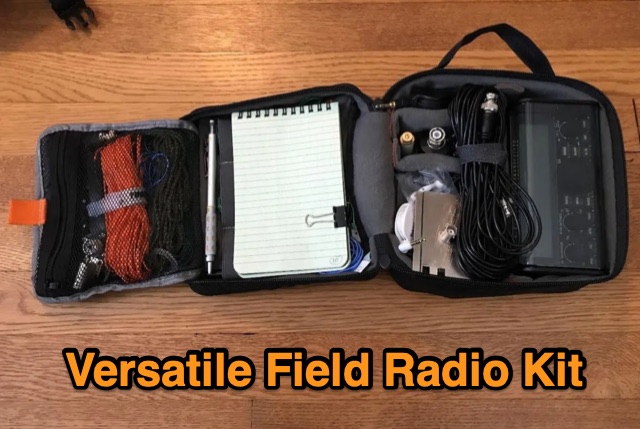 Alan (W2AEW) shares his comprehensive portable field radio kit, showcasing various antenna options and accessories for POTA activations. The kit, housed in a repurposed camera bag, features the Elecraft KX2 Shack a Box, AX1 antenna kit, and additional accessories. With thoughtful organization and adaptability, the kit offers flexibility for different deployment scenarios, ensuring efficient operation in diverse field conditions
 -
 Integrating a _Software Defined Radio_ (SDR) into an existing ham radio setup involves connecting it with a standard transceiver (TRX), power amplifier (PA), and antennas. The core component is a splitter box that facilitates the connection between the TRX and the SDR, allowing for simultaneous operation without modifying existing equipment. In receive mode, the splitter ties the antenna inputs of both the TRX and a direct conversion receiver (DC RX) together. During transmission, the DC RX input is grounded via a fast telecom relay controlled by the transceiver's -SEND signal, incorporating a 10ms delay for safety. The splitter box includes a 3.7 dB input attenuator for impedance matching and acts as a protective fuse for the DC RX input. Ground loops are mitigated using common mode balun transformers, while the DC RX input is insulated with a broadband transformer. An audio switch box complements the setup, enabling users to listen to either the main transceiver, the SDR output, or both simultaneously. This configuration ensures noise immunity and safety, with the splitter housed in a screened box made from PCB material. On-air tests, such as the CQ WW 160m CW DX Contest, demonstrate the system's effectiveness, showcasing the SDR's ability to handle crowded band conditions with superior selectivity and dynamic range. The SDR's narrow bandwidth filters and waterfall display provide significant advantages, allowing operators to detect weak signals amidst strong interference. The integration of SDR with conventional radios offers enhanced operational flexibility and performance in challenging environments.
 -
 This article discusses the evolution of portable amateur radio operations, focusing on optimizing backpack-carried equipment for outdoor use. The author shares his journey from using wheeled carts to developing an innovative backpack-mounted antenna system, emphasizing the transition from high-power (QRO) to low-power (QRP) operations to reduce weight. The piece details practical solutions for antenna mounting, equipment selection, and portable operations in challenging terrain, particularly along Ontario's Niagara Escarpment. The author's approach prioritizes mobility and functionality while maintaining effective radio communications in remote locations.
 -
 Delta loop antennas, particularly the 30 meter variant, offer unique advantages in terms of vertical polarization and omni-directional coverage. The construction process detailed by VE3VN highlights common mechanical and electrical challenges faced by amateur radio operators. Key design considerations include minimizing interaction with existing contest band antennas, achieving low elevation angles for DX chasing, and ensuring the antenna remains off the ground for agricultural clearance. The article provides specific measurements, such as the loop's height and feed point impedance, which are critical for optimizing performance. The use of NEC modeling software illustrates the importance of accurate resonance calculations, revealing how proximity to the tower affects both pattern and impedance. This practical account serves as a resource for hams looking to build effective antennas while navigating typical construction hurdles.
 -
 The K5USS 6 Meter Hentenna Project page on Hamuniverse provides detailed instructions on how to build a 6 meter directional antenna with 3.5 dBd gain. The project is presented with permission from K5USS, Charlie of Richardson, Texas. This directional antenna is a full wave loop on 6 meters, horizontally polarized but mounted vertically, with a 50 ohm impedance, ideal for 6 meter SSB operations. The page is useful for hams looking to construct their own directional antenna for improved performance on the 6 meter band.
 -
 This page provides information on how to design an Off-Center-Fed Dipole (OCFD) antenna, suitable for amateur HF bands like 80 meters or 40 meters. The antenna design allows for VSWR minima on multiple bands, making it a good choice for multi-band use. Learn how to create an OCFD antenna in either flat-top or inverted-Vee form using a single support. The page also offers tools to generate radiation patterns, VSWR charts, and antenna current diagrams for your specific antenna design, helping hams understand performance factors. Ideal for ham radio operators looking to build their own effective antennas.
 -
 This article from the July 1976 issue of Radio REF discusses the trend of large antennas for ham radio operators on the low bands. It specifically focuses on a Yagi 2 element antenna for the 80m band, detailing its construction and functionality. The author explains how the antenna can be switched between directing signals towards the West or East using a switch at the station. The article also provides technical details on the lengths of the director and reflector elements, and how they impact the antenna's performance. A useful resource for hams looking to build or understand Yagi antennas for the 80m band.
 -
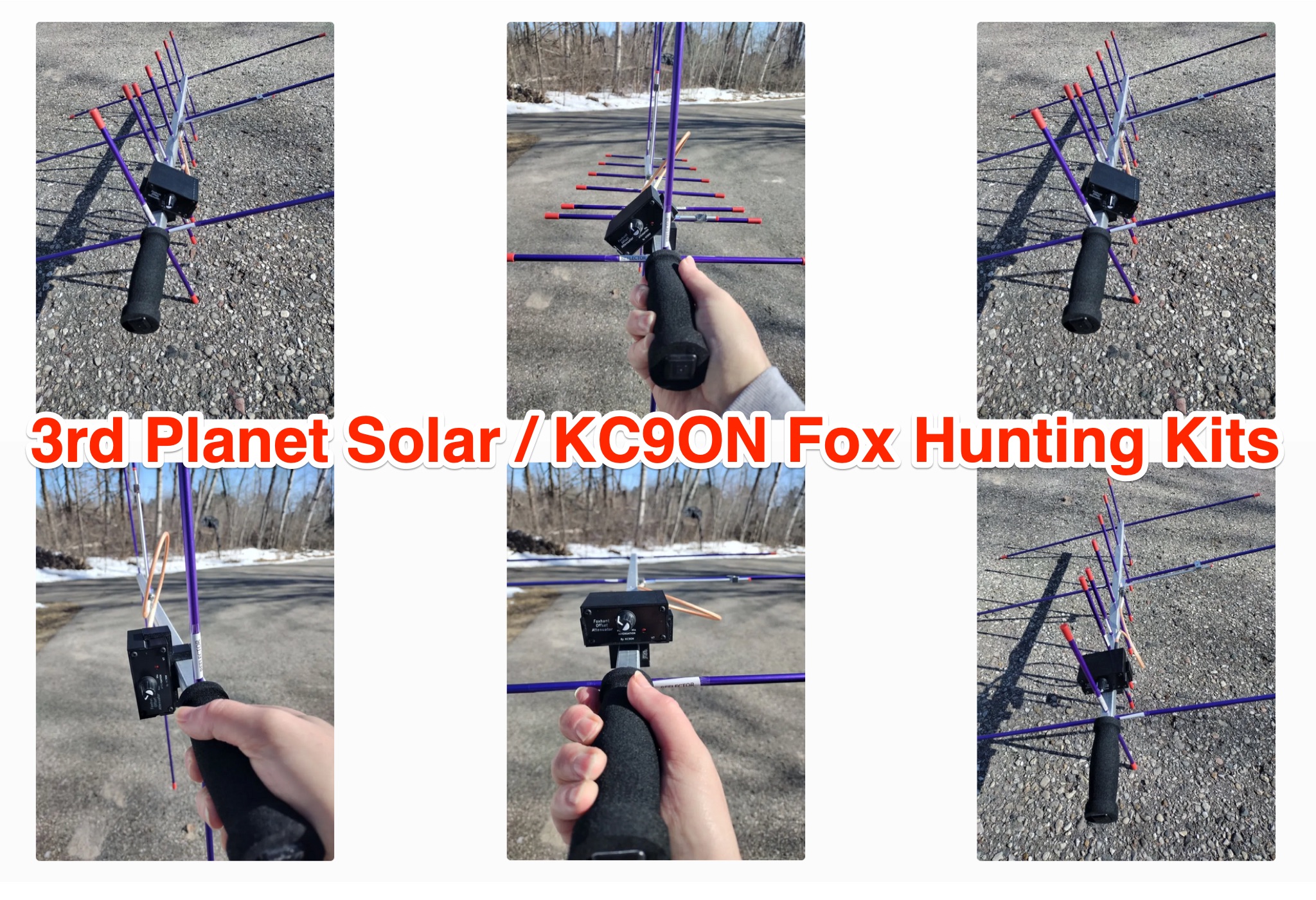 Explore the world of fox hunting with the Fox Hunt V7 Kits and Assembled Units. Learn about the different antennas used for fox hunting, such as the tape measure beam with an offset attenuator. Discover how to make your own WB2HOL beam antenna using PVC pipe, T's, and a tape measure. Find out how the offset attenuator works and how it can help you track down jammers and interference. Whether you're a seasoned fox hunter or just starting out, this page offers valuable insights and tips for improving your hunting skills.
 -
 This page by Arctic Peak provides a detailed explanation on how to use quarter-wave transmission lines as impedance transformers in ham radio antenna work. It explains how to match impedance values by connecting them with a λ/4 transmission line. The page also offers guidance on constructing your own transmission lines with specific impedance requirements, along with a calculator to determine the quarter wave length based on velocity factor and frequency. Useful for hams looking to optimize antenna performance and match transmission line impedance effectively.
 -
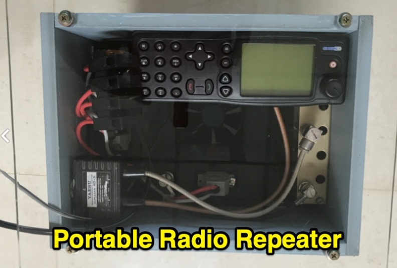 Demonstrates the construction of a portable 2-meter repeater system utilizing a **Yaesu DR-1X** transceiver, configured for both analog FM and C4FM digital voice operation. The design emphasizes portability, robustness, and effective thermal management, incorporating a "wind tunnel" airflow system with a fan to maintain transmit module temperatures at 38 degrees Celsius during continuous operation. The system integrates a diplexer, control head, and is housed in a compact, lightweight case weighing under 8kg, designed for single-person deployment. Covers practical considerations for field deployment, including power sources, antenna types, and the overall system architecture for public service events and emergency preparedness. The resource details the modular "wrap around" construction, showing how components like thermal switches for fan control and Anderson Powerpole connectors are integrated. It highlights the system's ability to provide reliable communications support for club activities and emergency communications.
 -
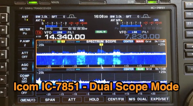 The Icom IC-7851 features the capability to display two scopes simultaneously, providing frequency, mode, and antenna information for each receiver. Users can choose between vertical or horizontal display orientations, and the dual scopes are also viewable on a high-resolution monitor connected to the radio. Additionally, the IC-7851 allows for mouse connectivity, enabling users to click on signals displayed on either scope for quick tuning. A demonstration video is available showcasing this dual scope functionality.