Search results
Query: microwave
Links: 148 | Categories: 20
Categories
- Manufacturers > Microwave
- Shopping and Services > Microwave
- Operating Modes > Microwave
- Antennas > Microwave
- Shopping and Services > Antennas > Microwave Antenna
- Manufacturers > Antennas > VHF UHF Microwave > Microwave antennas
- Manufacturers > Antennas > VHF UHF Microwave
- DX Resources > Beacons > 10 GHz Beacons
- Operating Modes > Aircraft scatter
- DX Resources > Beacons
- Manufacturers > Antennas > VHF UHF Microwave > Discone Antennas
- Manufacturers > Antennas > VHF UHF Microwave > Ground Plane Antennas
- Antennas > Horn
- Technical Reference > Mircrowave
- Manufacturers > Antennas > VHF UHF Microwave > Mobile Antennas
- Antennas > Patch
- Manufacturers > Antennas > VHF UHF Microwave > Quad Antennas
- Ham Radio > Clubs > Technical Specialty
- Manufacturers > Transverters
- Manufacturers > Antennas > VHF UHF Microwave > Yagi Antennas
-
 Traveling Wave Tubes , Conventional Traveling Wave Tubes, Microwave Power Modules manufacturer
 -
 WA1MBA article on RF connectors for microwave
 -
-
 OH3TR operates the OH3SHF microwave beacons on 2.3, 3.4, 5.7, 10 and 24 GHz
 -
 Amateur Television (ATV) operations involve transmitting and receiving live or recorded video and audio signals over amateur radio frequencies. Unlike narrow-band modes, ATV utilizes a wider bandwidth to convey video information, often requiring specialized transceivers, antennas, and signal processing equipment. This mode allows hams to share visual content, demonstrate projects, or conduct video conferences, typically on VHF, UHF, and microwave bands due to the bandwidth requirements. The SwissATV resource focuses on the technical aspects and community engagement surrounding ATV within Switzerland. It covers topics relevant to setting up ATV stations, understanding signal propagation at higher frequencies, and participating in local ATV activities. The site serves as a central point for Swiss ATV operators to exchange knowledge and coordinate transmissions, fostering the growth of this specialized amateur radio mode.
 -
 Operating in the **microwave** spectrum, Response Microwave, Inc. specializes in the design and manufacturing of RF and microwave signal processing components and subsystems. The company's product line encompasses a wide array of offerings, including Connectivity Series components, rotary joints, phase shifters, cable assemblies, surge protectors, terminations, Hybridline/Couperline products, circulators/isolators, directional couplers, quadrature hybrids, attenuators, custom assemblies, filters/diplexers, DC blocks & bias tees, power dividers/combiners, laser diodes & drivers, high-frequency connectors, and precision test accessories. This extensive catalog supports various applications requiring precise signal manipulation and transmission at elevated frequencies. The resource provides access to a comprehensive product catalog and a dedicated connector catalog, detailing specifications for components like **high-frequency connectors** and test cables. While specific performance data or comparative analyses are not directly presented on the main page, the breadth of products indicates a focus on providing foundational building blocks for microwave systems. The company emphasizes customer service and aims to be a reliable source for RF/Microwave/Optics product requirements, serving a growing customer base with its specialized component offerings.
 -
 High power, UHF, L-band, S-band, C-band, microwave frequency amplifier and oscillator devices, pulsed, CW, fixed-tuned, or tunable devices in the range of 600 MHz to 2000 MHz
 -
 The Kentucky Contest Group (KCG) website, maintained by N4GN, serves as a hub for amateur radio operators interested in **radiosport** contesting within Kentucky and southern Indiana. It details the group's dedication to promoting contesting, offers links to KCG officers, membership rosters, and upcoming meetings, and provides access to an active KCG e-mail reflector and Facebook Group for member communication. The site also features a comprehensive list of N4GN's recommended ham radio web picks, covering various categories like contesting resources, DXing, VHF/UHF/Microwave, and propagation information. The KCG's map center coordinates were updated on May 16, 2015, shifting approximately 16.5 miles SSW to 37° 21' N, 85° 39' W. Despite acknowledging current inactivity and an outdated web presence, the group remains operational, exploring options for reorganization, including a potential merger with the Tennessee Contest Group (TCG), which was ultimately rejected. The site emphasizes that membership applications are considered from anyone with a genuine interest in contesting.
 -
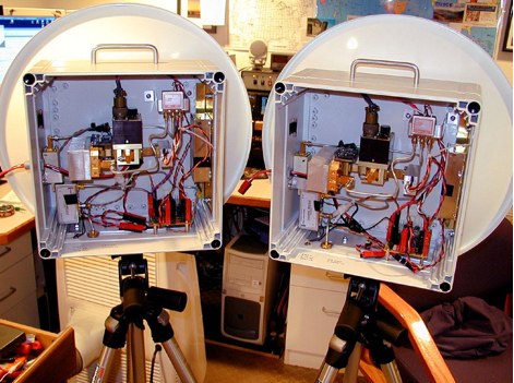
 Developing operational amateur radio equipment for the 134 GHz band presents significant technical challenges, particularly in frequency generation and stability. This resource details the construction of a 134 GHz system, outlining its architecture with separate transmit (Tx) and receive (Rx) modules, each employing a local oscillator (LO) and RF head units. The system utilizes a dual Flann 50 GHz lens-type horn antenna configuration for optimal signal coupling. The transmit path incorporates an LMX2541 synthesizer chip operating at approximately 2.8 GHz, referenced by a 10 MHz double-oven Morion OCXO for exceptional stability. This signal is multiplied through a series of stages (X4, then X2) to generate a 22.4 GHz signal, which subsequently drives a dual series diode multiplier to produce the final X6 signal for 134 GHz operation. The receive side features an anti-parallel diode mixer coupled to a 144 MHz transceiver via a preamplifier, ensuring effective downconversion. Operational mode is CW, achieved by keying a multiplier stage. The project includes images of the Tx and Rx head units and describes a successful 3.5 km test with G8ACE, demonstrating stable signal tones due to PLLs locked to OCXOs at both ends, confirming the system's robust performance.
 -
 Distribute Coax Cables and Connectors for VHF UHF and Microwave
 -
 Operating a modern amateur radio station, particularly for advanced digital modes or microwave experiments, often requires precise test and measurement equipment. This resource from NI (National Instruments), now part of Emerson, showcases a wide array of hardware and software solutions designed for demanding test objectives. Their portfolio includes modular instruments and configurable software interfaces, such as _LabVIEW_ and _TestStand_, which integrate AI assistance via _NI Nigel™ AI_ for code completion and sequence building. For those involved in RF and microwave work, the offerings extend to vector signal transceivers, RF signal generators, software-defined radios, and spectrum analyzers. These tools are crucial for characterizing antenna performance, optimizing transceiver circuits, or developing custom radio systems. The company emphasizes its 50 years of innovation, with 40 years dedicated to _LabVIEW_, highlighting a long-standing commitment to engineering solutions. The site also details products for data acquisition, electronic test, and wireless design, covering components like CompactDAQ modules for precise sensor measurements and various communication bus interfaces. Their events and perspectives sections offer insights into topics such as 5G technology and strategies for breaking out of testing silos, providing a broader context for their measurement solutions.
 -
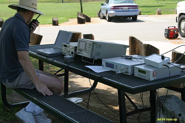
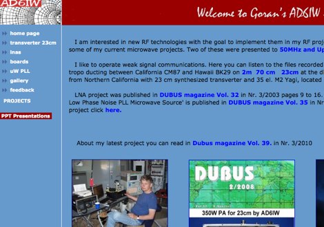 A website dedicated to microwave operations and technical projects by AD6IW
 -
 The San Bernardino Microwave Society, operating under the callsign _W6IFE_, serves as a significant technical hub for amateur radio operators specializing in frequencies above 1 GHz. This organization's influence extends across Southern California, providing a centralized resource for advanced RF experimentation and **regional frequency management** within the microwave spectrum. Its permanent value lies in its extensive archive of technical papers and project documentation, which are critical for operators engaged in high-frequency design and deployment. The society's infrastructure is primarily intellectual, focusing on the dissemination of specialized knowledge rather than a conventional repeater network. It offers a robust collection of technical papers from prominent members like K6PIP, K6BLG, and WA6EXV, covering topics such as Rubidium oscillator data, logging software, and filter design. This resource facilitates advanced amateur radio operations, including participation in microwave contests and the development of custom transverters for bands like 24 GHz. The site also details various member projects, such as the Owens Valley Radio Observatory Project, showcasing practical applications of **RF propagation analysis** and system integration. DXZone Focus: Microwave | Technical Papers | RF Propagation | Contest Results
 -
 Web site dedicated to microwave ham radio operations and portable activities by G8BKE
 -
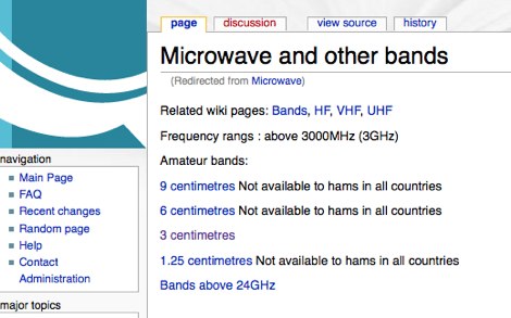 Microwave band plan - frequancy assigned to ham radio service
 -
 Demonstrates MegaPhase's extensive product line of RF and microwave coaxial cable assemblies and components, engineered for demanding applications up to 110 GHz. Key offerings include _Test & Measurement Cables_ with superior phase and amplitude stability, _RF & Microwave Cables_ utilizing _GrooveTube®_ technology for high power systems, and a range of RF components like directional couplers and power dividers. The site details specific cable types such as _Alumibend™_ for space-qualified, ultra-light applications through 90 GHz, and armored cables designed for rigorous environments up to 50 GHz, emphasizing their robust mechanical strength and measurement repeatability. The resource highlights applications across diverse sectors, including space programs like the _Hayabusa_ mission, global security (C5ISR), military airborne systems (MIL-T-81490), telecom, and automated testing. It also provides technical insights through "How To" guides on measuring amplitude/phase stability vs. flexure and proper connector cleaning. The company's commitment to quality is underscored by its rigorous testing protocols and a strong warranty, ensuring reliable operation in critical systems.
 -
-
 Delivering confidence to confront the most challenging microwave and RF designs. Spectrum Analyzers by Tektronix
 -
 G3PHO website dedicated to the microwaves operations
 -
 A web site maitained by KK6MK about microwave and related technical material
 -
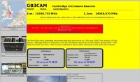 Two beacons in 3 and 1.2 cm band, 10368.755 MHz and 24048.870 MHz
 -
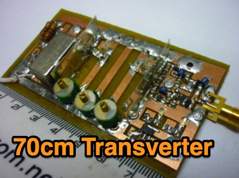 The project in this article illustrates how to do this in a simple and low cost way so that you can easily access the microwave bands using the existing HF or HF/VHF transceiver as IF.
 -
 Stanley Grixti - 9H1LO is I.A.R.U. Microwave Manager and Vice-Secretary for M.A.R.L
 -
 Equipment and Components for the RF and Microwave industry. AtlanTecRF is a global supplier of microwave and RF components and equipment to the aerospace, defence, telecommunications and scientific markets.
 -
 High Speed Multimedia (HSMM) radio, as introduced by John Champa, K8OCL, represents a significant advancement in amateur radio's digital capabilities, moving beyond traditional keyboard modes like packet radio. This initiative, driven by ARRL's Technology Task Force, focuses on developing high-speed digital radio networks capable of up to 20 megabits per second. HSMM primarily facilitates digital voice (DV) and digital video (ADV), enabling real-time video transmission from emergency scenes to an EOC without expensive ATV gear, often requiring only a laptop, a PCMCIA card, a digital camera, and a small antenna. The working group's initial efforts concentrate on cultivating microwave skills within the amateur community to build and support portable and fixed high-speed radio-based local networking, or **RLANs**. These networks prove invaluable for RACES and ARES organizations, as well as homeland security and other emergency communications. Field Day exercises and simulated emergency tests (SETs) are encouraged to hone skills in rapid site surveys and deploying broadband HSMM microwave radio networks, with examples like linking Field Day logging stations or antenna test results at the Midwest VHF-UHF Society Picnic 2003. Getting started with HSMM often involves adapting off-the-shelf **IEEE 802.11** (WiFi) equipment to comply with amateur radio regulations, typically operating in the 2.4 GHz ISM bands. While consumer WiFi gear has range limitations under Part 15 rules, proper setup under amateur regulations can extend coverage significantly, with test networks like the Hinternet achieving 5-15 mile ranges at 54 M bit/s using small mast-mounted dish antennas. Careful selection of equipment with external antenna ports, high transmit power, and low receive sensitivity is crucial, along with using low-loss coaxial cable like LMR-400 for optimal performance at these frequencies.
 -
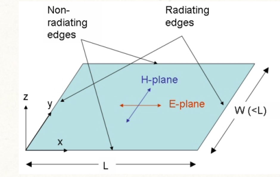 Article about the microstrip patch antennas, and in particular the rectangular, single-polarization microstrip antennas, commonly abbreviated MSA.
 -
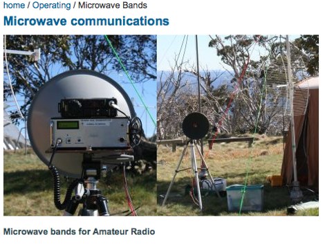 Introduction to operating on microwave bands at VKFAQ
 -
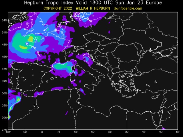 The areas noted in the forecast have the necessary atmospheric conditions to produce tropospheric bending of VHF, UHF and/or microwave radio waves. Tropospheric bending extends the range of radio & TV stations well beyond their normal limit and thus increases interference amongst stations as well.
 -
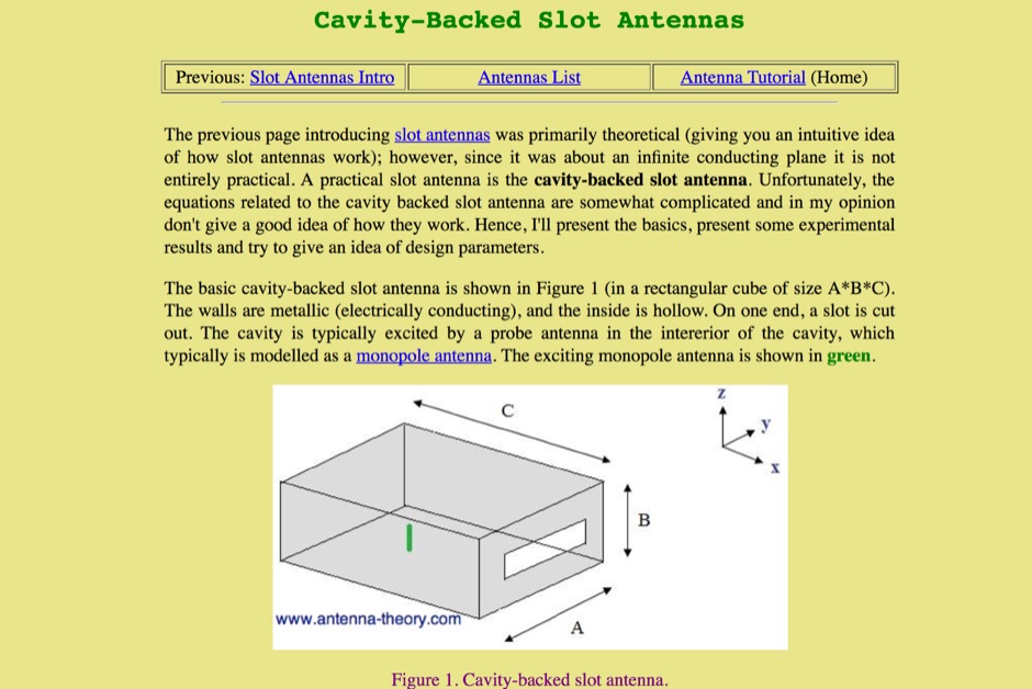 A cavity backed antenna is a practical slot antenna tipically used in microwave applications
 -
 Microwaves101 provides an extensive repository of information covering fundamental principles of microwave design, targeting engineers and radio amateurs interested in the higher frequency spectrum. The site features a detailed _encyclopedia_ of microwave terms and concepts, alongside practical design considerations for various components and systems. It serves as a foundational reference for understanding RF propagation, transmission lines, and active/passive microwave circuits. The resource includes numerous calculators for impedance matching, filter design, and other critical RF parameters, facilitating hands-on project development. Discussions on **10 GHz** equipment and **24 GHz** projects highlight practical amateur radio applications, extending to operations up to 134 GHz. Content spans from basic theory to advanced topics like MMIC design and antenna characteristics, supporting both educational and practical endeavors in microwave technology.
 -
 Details Amphenol Connex's product range, focusing on RF connectors, adapters, and cable assemblies. The company produces common radio frequency interfaces such as _BNC_, _SMA_, and _TNC_ connectors, alongside numerous other specialized designs. These components are critical for establishing reliable signal paths in amateur radio stations, ensuring proper impedance matching and minimal signal loss across various frequency bands. The manufacturing process emphasizes precision engineering to meet the demanding specifications of RF applications, from HF to microwave frequencies. Product lines support diverse coaxial cable types, facilitating custom cable assembly for specific station configurations. The extensive catalog provides solutions for both fixed station installations and portable operations, addressing the needs of contesters, DXers, and general amateur radio operators.
 -
 Dealer in HF, RF and microwave components based in Italy, offering a wide product catalog for amateur radio projects and more.
 -
 Torbay Amateur Television and Microwave Group GB3TB 23cms Repeater at IO8ØFL
 -
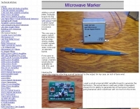
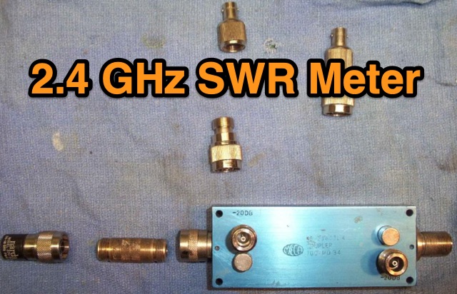 This is a simple 2.4 GHz SWR meter which is based around surplus microwave hardware which can be easily found. The main component is a MECA -20/-20 dB Directional Coupler which has a frequency range of approximately 700 MHz to 2.5 GHz.
 -
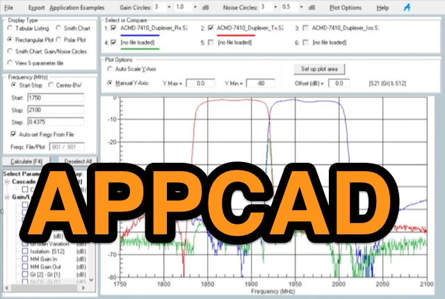 Free windows application for RF Microwave and Wireless applications. AppCAD is useful for the design and analysis of many circuits, signals, and systems using products from discrete transistors and diodes to Silicon and GaAs integrated circuits. AppCad is a unique suite of RF design tools and computerized Application Notes to make your wireless design job faster and easier
 -
 Details the custom manufacturing of high-performance RF coaxial cable assemblies, emphasizing the use of _Times Microwave_ and other premium U.S.-made components. The company operates as a Small Business within the Albany, GA, HUB ZONE, with all warehousing and production facilities located in Southern Georgia, approximately 150 miles south of Atlanta. MPD Digital specializes in bespoke cable solutions for diverse applications, including amateur radio, WiFi, satellite, and cellular systems. Highlights the availability of thousands of connector configurations, supported by expert engineers on staff. The facility's total plant area and commitment to rapid shipping on custom cable assembly orders are noted. A specific product, the _MPD-400PVC Super Flex Coaxial Cable_, is mentioned as a recent update.
 -
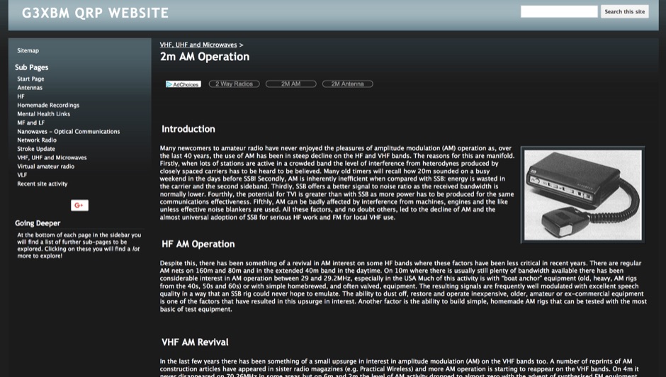 An article on amplitude modulation (AM) operation on VHF bands.
 -
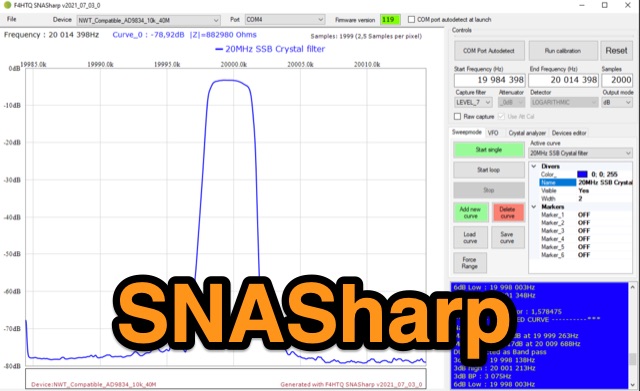 SNASharp is a free software application designed to work with scalar network analyzers compatible with NWT software from DL4JAL. It is used to measure and analyze the scattering parameters (S-parameters) of microwave devices. Provide several measurements and analysis tools including Smith chart, Polar plot, S-parameter tables, Transmission line calculator
 -
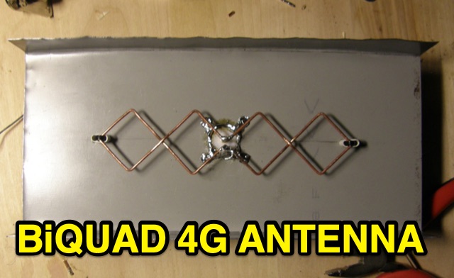 This is basic instructions for homemade 4G Antenna working on 2600 MHz UMTS featuring 13 14 dBi gain. This antenna is desigend to resonate on microwave frequencies in two segments from 2500 to 2570 MHz for Uplink, and from 2620 to 2690 MHz for Downlink.
 -
 Microwave Filter Company is a leader in the design, development and manufacture of high quality passive electronic filter products in the 5 Hz to 50 GHz frequency spectrum.
 -
 Direct conversion receivers (DCR) are gaining renewed interest due to advancements in semiconductor technologies and their suitability for integration in compact, low-cost, multi-standard applications. Unlike traditional superheterodyne receivers, DCR eliminates image frequencies and bulky off-chip filters but introduces challenges like DC offsets, nonlinearity, and noise issues. This tutorial explores DCR's historical development, compares it with other receiver architectures, and addresses its inherent obstacles. DCR's potential for integration and compatibility with software-defined radio highlights its role in modern communication systems despite its technical complexities.
 -
 The 8m ISM band, a unique frequency range between 10m and 6m, holds potential for amateur radio enthusiasts, yet it remains largely unallocated. This spectrum offers fertile ground for research and self-training. The author's experience with low-power transmissions and WSPR testing highlights the band's capabilities and the need for a narrow, speech-free amateur allocation to encourage experimentation. Discover the world of 8m ISM radio exploration and its future possibilities.
 -
 Manufacturer of 50MHz, 70MHz, 144MHz, 222MHz, 432MHz, 900MHz or 1.2GHz transverters and VHF UHF amplifiers
 -
 Getting started with Aircraft scatter, defined as the process of scatter radio waves of the body of a traveling aircraft in order to enhance the distance possible to bridge on VHF, UHF and microwaves. The ACS path, Equipment requirement and Operating techniques
 -
 The article explores the concepts of return loss, VSWR, and S11 within the context of microwave engineering, highlighting the confusion arising from their definitions. It clarifies that these parameters, while seemingly distinct, fundamentally describe the same phenomenon related to wave reflection and transmission in microwave circuits. The discussion emphasizes the historical context and mathematical relationships among these terms, revealing that their interpretation can vary significantly across different engineering disciplines. Ultimately, it advocates for a pragmatic approach to using these parameters based on familiarity rather than strict definitions.
 -
 This excel workbook addresses the issue of power loss in transmission lines with complex characteristic impedance ZoZo​. It illustrates the discrepancy between actual loss (0.35 dB) and matched line loss (0.6 dB) using a simplified example, highlighting potential software tool limitations. The RF Feedline Power-Loss Calculator provides accurate end-to-end loss assessments for both microwave and RF applications. This tool is suitable for engineers and students and is compatible with Windows versions of Excel 2016 or later, though it is not compatible with Macintosh systems.
 -
 The W6PQL 23cm Beacon Project describes a **1296 MHz** beacon designed for microwave propagation studies and equipment testing, capable of 30 watts output. It utilizes a PIC 16F628A microcontroller to generate CW and FSK keying for a crystal oscillator, followed by a series of frequency doublers and triplers to reach the target frequency. The final power amplification stage employs a Mitsubishi M57762 module, providing a robust 10-watt RF output. The design emphasizes stability and reliability for continuous operation, with the microcontroller code, written in assembly, provided for customization of the beacon's callsign and message. Originally located in CM97am and aimed at 140 true, the beacon used four 4-foot Yagis stacked vertically for a total ERP of 3kW. The article includes schematics, parts lists, and construction notes to guide builders, along with antenna pattern measurements. Although the beacon itself is no longer in service as of August 2010, the detailed documentation remains a valuable reference for amateur radio operators interested in building similar **microwave** projects or understanding beacon operation.
 -
 This online construction guide details the assembly of a signal generator specifically for the **13cm band** (2.4 GHz). The curriculum focuses on the integration of a Voltage Controlled Oscillator (VCO), specifically the ROS-2400, to produce a stable RF signal. The resource outlines the necessary components for frequency generation and output, including the use of a Mini-Circuits MMIC amplifier for signal conditioning. The construction protocol involves configuring the ROS-2400 VCO to operate within the 2.3 GHz to 2.45 GHz range, ensuring frequency coverage for amateur radio _microwave experimentation_. The guide specifies the output power level, approximately 70mW, directly from the MMIC stage, indicating its application as a low-power instrumentation source rather than a transmit-capable device. This project provides a practical example of constructing a dedicated test instrument for microwave frequency measurements and system alignment on the **13cm band**. DXZone Focus: Construction Guide | 13cm Signal Generator | VCO Integration | Microwave Experimentation