Search results
Query: nec demo
Links: 112 | Categories: 0
-
 This comprehensive article dispels common misconceptions about Standing Wave Ratio (SWR) in amateur radio. The author explains that SWR is not an antenna property but a measure of the entire antenna system, representing the mismatch between transmission line and load impedance. Contrary to popular belief, modest SWR values (under 3:1) typically cause minimal power loss in HF applications. The article demonstrates mathematically why obsession with achieving 1:1 SWR is often unnecessary, explains when SWR matters more (QRO, QRP, VHF/UHF), and explores effective matching techniques including proper ATU placement and quarter-wavelength transformers.
 -
 Demonstrates a specific impedance matching technique for resistive loads ranging from 22.2 to 45 ohms, connecting them to a 50-ohm transmission line. The method employs series sections of 50-ohm and 75-ohm coaxial cables, with graphical data illustrating the required cable lengths (L1 and L2) in wavelengths for a perfect match. This approach is particularly useful for feeding **vertical** and **Yagi antennas**. The resource provides a practical example of matching a 25-ohm Yagi antenna at 50.150 MHz, specifying the use of RG-58C/U (50 ohms) and RG-59B/U (75 ohms) cables, both with a 66% velocity factor. It calculates the precise physical lengths in centimeters and inches for the required cable sections. Additionally, the document briefly discusses integrating a balun at the load end, suggesting methods such as coiling a cable section or utilizing ferrite beads to create a W2DU-type balun. The presented methodology offers a clear, data-driven solution for common antenna impedance challenges.
 -
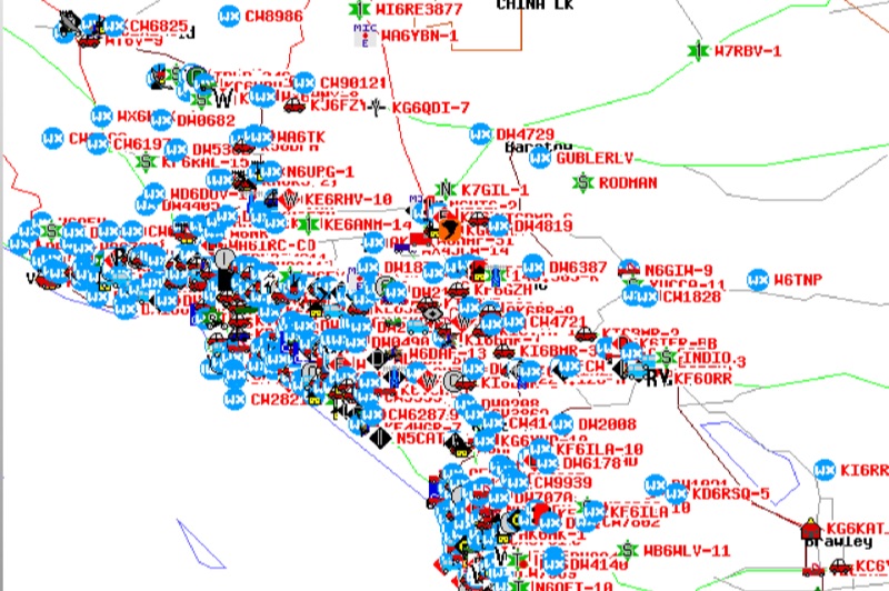 Demonstrates the Automatic Packet Reporting System (APRS) as a radio-based system for real-time tactical data exchange, leveraging the internet for messages, alerts, and bulletins to enhance situational awareness. It explains how APRS displays data on a map, integrating objects with GPS coordinates, weather stations, and alerts, clarifying its primary function as vehicle tracking despite broader capabilities. The document traces APRS development from the late 1980s by Bob Bruninga, WB6APR, through its evolution from Connectionless Emergency Traffic System (CETS) to Automatic Position Reporting System, and finally to Automatic Packet Reporting System with widespread GPS availability. Specific functionalities covered include real-time position and status reporting, message and bulletin exchange, weather data, DF bearings, RF connectivity plots, and local object display. Newer features like Global Email, CQSRVR, APRStt (APRS touchtone) for DTMF-based position reporting on frequencies like 146.58 MHz, and AVRS (Automatic Voice Relay System) for callsign-to-callsign linking via Echolink or IRLP, particularly with transceivers like the D710, are detailed. The resource also mentions AI-FI (APRS WIFI) for laptop integration and the use of the AX.25 protocol on 144.390 MHz in North America. It further describes the role of digipeaters and Internet Gateway stations (IGates) in transporting packets and connecting the on-air APRS network to the APRS Internet System (APRS-IS). The document explains APRS as a random ALOHA network, emphasizing channel loading considerations.
 -
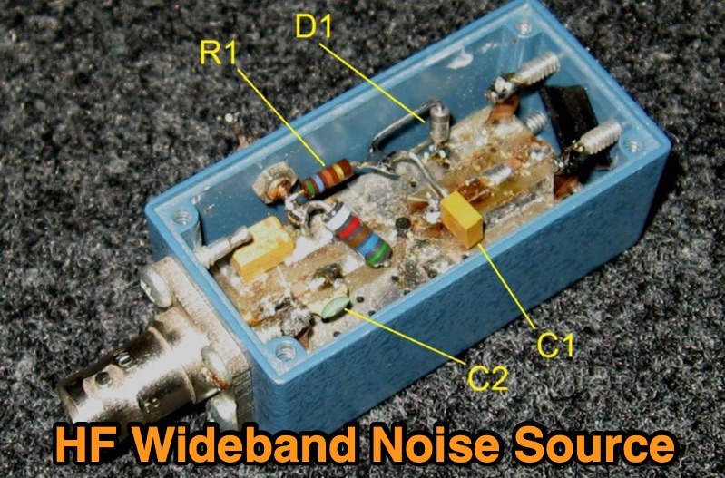 Details the construction of a **wideband noise source** for HF filter alignment, specifically targeting transceivers such as the Elecraft K2. The design modifies a Down East Microwave (DEMI) MMIC amplifier board, part number MMICPCB, by integrating a 1N4735A zener diode, 560-ohm resistors, and 4.7 nF, 10 nF, and 22 µF capacitors. This modification enables the board, originally configured for a MAR-6 MMIC (with MAR-1 as an alternative), to generate noise suitable for procedures like the K2's "CAL FIL" function. The resource provides a **schematic** and a comprehensive bill of materials, including specific component values for replication. It outlines the practical steps involved, such as removing the input connector and integrating the new components into the existing MMIC amplifier board layout. The output is optimized for wideband HF applications, ensuring compatibility with various filter alignment tasks. This project focuses on practical implementation, demonstrating how to repurpose readily available components for a critical test instrument. It offers a cost-effective alternative to commercial noise sources, leveraging existing amateur radio hardware for enhanced station maintenance and performance.
 -
 Constructing a 4:1 Guanella current balun involves cross-connecting two 1:1 current baluns. At the low-impedance end, transmission lines from each balun are connected in parallel, while at the high-impedance end, they are connected in series. This configuration allows the device to achieve a 1:4 impedance ratio, effectively transforming a 200-ohm load to 50 ohms. The balun described utilizes **FT240-43 toroids** wound with 2.5mm2 twisted pair cable for 8 turns, intended for use with a 20m **Deltaloop antenna**. Measurements performed with a 200-ohm resistor demonstrate satisfactory VSWR and impedance characteristics across the HF bands. The article compares the performance of 2.5mm2 cable versus 1mm enameled wire, recommending the former for superior efficiency. Emphasis is placed on maintaining short core-terminal connections to optimize performance. Additional considerations include the option of integrating a separate Common Mode Choke (CMC) for enhanced common mode current suppression, especially if the balun's inherent suppression is not prioritized.
 -
 Demonstrates the design and modeling of a **160m** vertical antenna, dubbed the "WindoVert," specifically for urban amateur radio operators with limited space. The resource covers the theoretical underpinnings of antenna height and radiation patterns, using EZNEC software to analyze current distribution and 3D radiation patterns for various configurations, including a Marconi-style "T" antenna. It details the integration of existing antenna components, such as a Carolina Windom balun and line isolator, into the new vertical setup, and the practical measurement of feedpoint impedance using an antenna analyzer. The article further explores the challenges of achieving low-angle radiation on Top Band, emphasizing the critical role of radial systems and mitigating ground loss. Author VE1ZAC presents EZNEC models illustrating the impact of lumped components and discusses the practical considerations of resonant frequency adjustment and impedance matching for **QRP** operation. The text details the calculation of required loading coil inductance and capacitance, and shares field results, including successful DX contacts on 160m and unexpected excellent performance on 30m.
 -
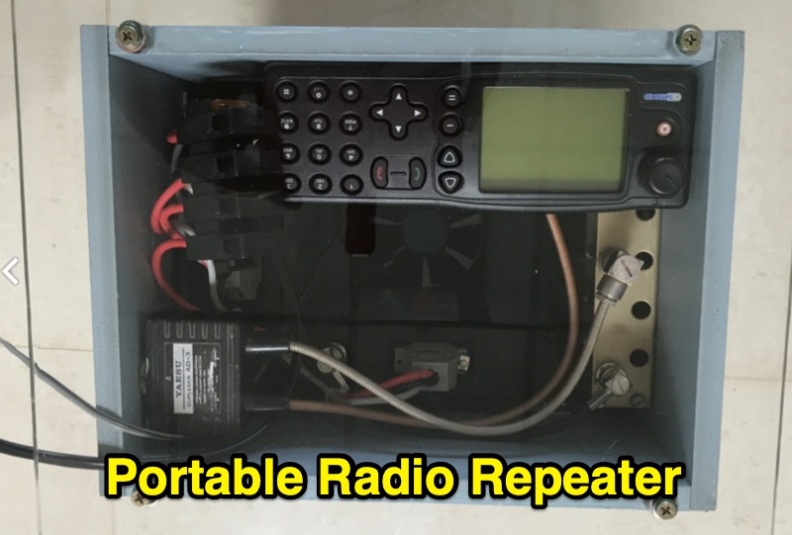 Demonstrates the construction of a portable 2-meter repeater system utilizing a **Yaesu DR-1X** transceiver, configured for both analog FM and C4FM digital voice operation. The design emphasizes portability, robustness, and effective thermal management, incorporating a "wind tunnel" airflow system with a fan to maintain transmit module temperatures at 38 degrees Celsius during continuous operation. The system integrates a diplexer, control head, and is housed in a compact, lightweight case weighing under 8kg, designed for single-person deployment. Covers practical considerations for field deployment, including power sources, antenna types, and the overall system architecture for public service events and emergency preparedness. The resource details the modular "wrap around" construction, showing how components like thermal switches for fan control and Anderson Powerpole connectors are integrated. It highlights the system's ability to provide reliable communications support for club activities and emergency communications.
 -
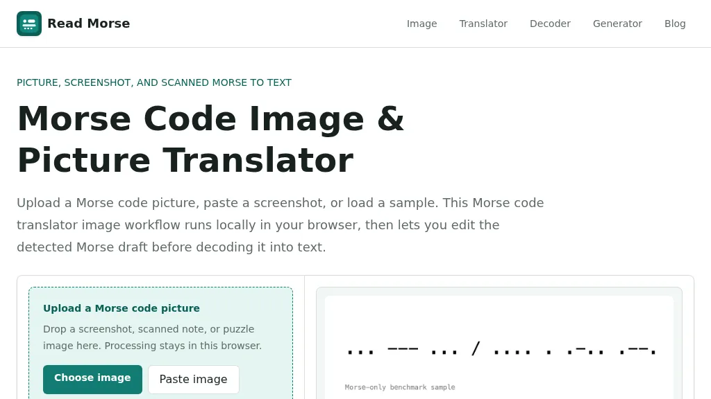 Decoding Morse code from visual sources like screenshots, scanned documents, or photographs presents unique challenges compared to audio-based reception. This web-based utility addresses these by allowing users to upload or paste images containing Morse code, which is then processed entirely within the user's browser, ensuring privacy. The tool identifies individual marks, classifying them as dots or dashes, and estimates letter and word spacing to generate an editable Morse draft. Users can refine the detection by utilizing controls for cropping, rotation, contrast boosting, and manual threshold adjustment, which are crucial for overcoming issues like low contrast, skewed baselines, or extraneous graphics. After the initial detection, the generated Morse draft, such as _... --- ... / .... . .-.. .--?_, can be manually corrected before being translated into plain text. The system provides confidence indicators and warnings to highlight potential ambiguities in the decoded output, prompting users to review and make necessary edits. This specialized approach differs from general OCR engines by focusing on the distinct patterns of Morse marks and gaps, rather than attempting to read standard alphanumeric characters. The tool supports common image formats like PNG, JPG, JPEG, and WebP, and includes sample images for benchmarking its performance, demonstrating its capability to handle various image qualities and complexities.
 -
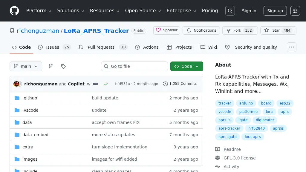 Demonstrates a LoRa APRS Tracker project featuring a comprehensive menu system for message management, weather requests, and monitoring nearby trackers. The device supports adjustable display eco mode and screen brightness, optimizing power consumption by dynamically changing processor speed from 240MHz to 80MHz. GPS beacons are encoded for efficient RF transmission, and an OLED screen displays altitude, speed, course, _BME280_ weather data, or new message counts, along with recently heard stations. Bluetooth connectivity enables operation as a TNC with Android (APRSdroid) or iPhone (APRS.fi app), providing LED and sound notifications for transmissions and received messages. The integrated BME280 module facilitates weather data display and transmission, with Winlink mail support via _APRSLink_. The tracker can switch between **three major LoRa APRS frequencies** worldwide, offering versatile global operation.
 -
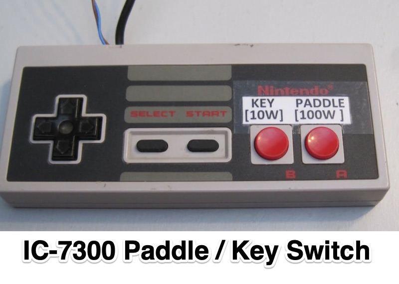 Demonstrates an **Arduino-based** solution for the Icom IC-7300 transceiver, specifically addressing the operational inconvenience of switching between a CW paddle and a straight key. The project leverages the IC-7300's **CI-V bus** (Computer Interface 5) to provide instant keyer type selection and two preset power levels, bypassing the rig's menu system which otherwise requires eight button presses. This implementation utilizes the 3.5mm CI-V connector, leaving the USB port free for CAT control and the internal soundcard, a critical design choice for integrated station setups. The system's utility is particularly evident for CW operators who frequently alternate between keying methods during contesting or general operating. The article details the hardware setup, including an Arduino Nano, a 3.5mm jack for CI-V, and pushbuttons for control. An update in 2023 expanded the project to incorporate an 8-button Nintendo controller, enhancing user interface flexibility and demonstrating the adaptability of the initial design for further customization and feature integration.
 -
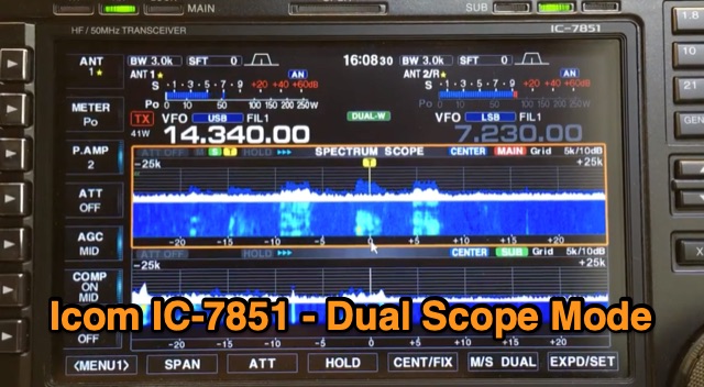 The Icom IC-7851 features the capability to display two scopes simultaneously, providing frequency, mode, and antenna information for each receiver. Users can choose between vertical or horizontal display orientations, and the dual scopes are also viewable on a high-resolution monitor connected to the radio. Additionally, the IC-7851 allows for mouse connectivity, enabling users to click on signals displayed on either scope for quick tuning. A demonstration video is available showcasing this dual scope functionality.
 -
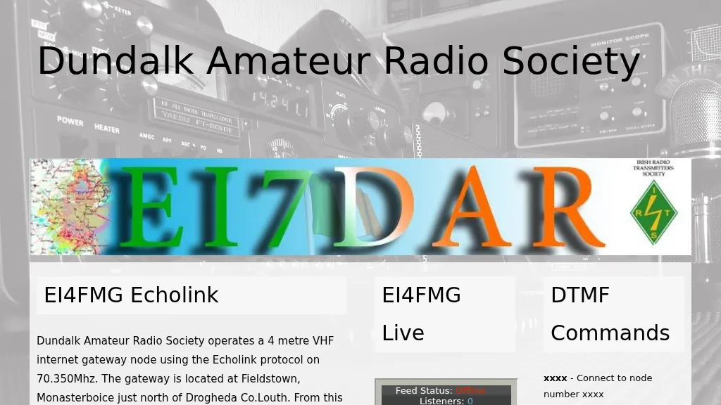 Operating an **Echolink** gateway on the 4-meter band presents unique opportunities for extending VHF communications, as demonstrated by the EI4FMG node. Situated at Fieldstown, Monasterboice, this gateway provides coverage across a significant portion of Ireland's east coast, leveraging a Tait TM8100 radio and an EI4JR Echolink interface logic. My own experience with similar setups confirms the importance of strategic site selection for maximizing reach, particularly with a 122-meter elevation above sea level. Access to the EI4FMG gateway, identified by node 57006, requires a **CTCSS** tone of 88.5 Hz, a standard practice for managing access and minimizing interference on shared frequencies. The system transmits with 15 watts of power and utilizes a Sigma CAT70 @5MAGL antenna, a configuration well-suited for regional VHF coverage. The gateway also features an auto-ID every 8 minutes, ensuring compliance and clear station identification. Users can interact with the gateway using various DTMF commands, allowing for connections to specific nodes, random repeater/link or conference nodes, and managing disconnections. These functionalities streamline the process of linking into the broader Echolink network, enabling local VHF operators to communicate globally through the internet backbone.