Search results
Query: out put power
Links: 128 | Categories: 2
-
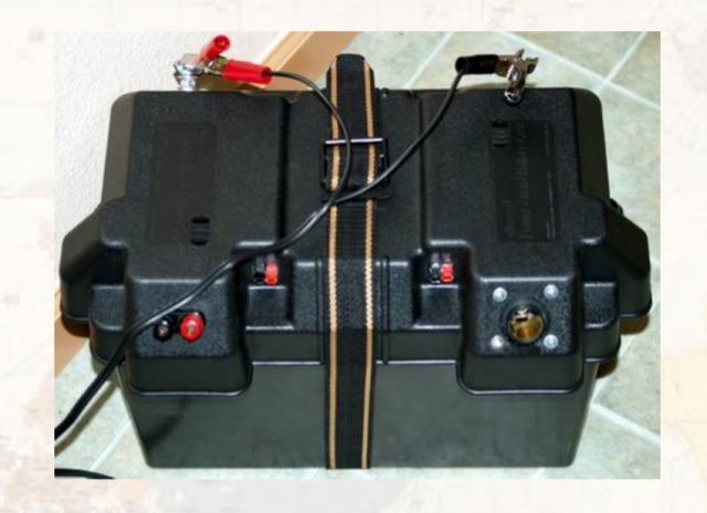 The article describes how to build a 12V emergency power supply for amateur radio stations. Starting with a basic jump-start system, the author upgraded it using a Group 27 deep-cycle battery and a 45W photovoltaic solar system, adding connectors and outputs for various devices. The system is portable, affordable (under $100), and capable of powering a station for 20 hours. The author emphasizes keeping batteries charged with a float charger and offers assistance to fellow club members interested in building their own power supply.
 -
 QRP is a Q-code originally meaning reduce power, but now has come to mean operating a radio that outputs 5 watts or less for CW or 10 watts for SSB.
 -
 Over 1000 _Elecraft_ KX2 owners have benefited from the Kx22 Heatsink, experiencing cooler rig temperatures and higher output powers. PAE manufactures these heatsinks, along with AC power supplies for HF transceivers, remote power relays, and Ethernet relays, with all machined products manufactured in the **USA**. PAE distributes _Fair-Rite_ Mix 31 ferrite snap-it cores and toroid cores, essential for RFI suppression and impedance matching in amateur radio setups. The product line also includes commercial monitoring antennas, UQUI transformers, ULP AC power filters, and 3M conductive adhesive copper tape, catering to various station build-out and maintenance needs. The AM1 Portable Antenna Mount System and its AM1-VA Multi-Angle Adapter offer flexible antenna deployment options. PAE ensures careful packing of fragile ferrite products, with shipping cost adjustments communicated post-order for larger, heavier combinations to guarantee safe delivery.
 -
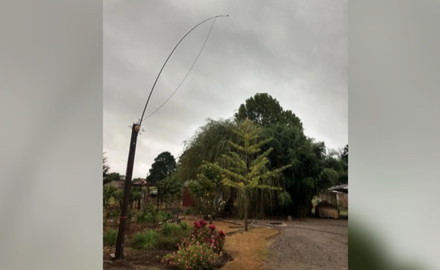
 Learn how to build a compact and efficient HF antenna for ham radio operators with limited space. Follow the author's journey from experimenting with different antennas to creating a magnetic-mounted antenna that covers 7MHz to 30MHz without the need for an ATU. Discover how a portable flagpole can be repurposed for radio communication, allowing you to operate with 100 Watts power output. This project provides a cost-effective solution for hams looking to set up a reliable antenna on their car roof in just 30 seconds.
 -
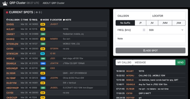 The QRP Cluster provides a dedicated platform for _QRP_ (low power) amateur radio operators to self-spot their on-air activity. This web-based service allows users to post real-time information about their current operating frequency, modulation mode, equipment used, and transmit power. It facilitates QRP-to-QRP contacts and helps other low-power stations locate active QRP signals across various bands. Unlike general DX clusters, the QRP Cluster focuses exclusively on low-power operations, fostering a community for QRP enthusiasts. It enables operators to share details such as **5 watts** or less output, often specifying antenna types or unique portable setups. The platform supports the discovery of QRP stations for casual QSOs, contests, and award hunting, enhancing visibility for stations that might otherwise be overlooked on higher-power clusters.
 -
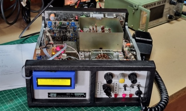 This article describes an upgrade to the Kestrel transceiver, replacing its LCD display with a 0.91-inch OLED screen for improved sound quality. VFO boards from Denys VK3ZYZ were integrated, particularly a Nano VFO board. The author shares details about the setup and the resulting enhancements, along with images of the modified components. The transceiver is now optimized for various frequencies and operates at a power output of approximately 120 W pep. More information about the boards can be found on the provided website.
 -
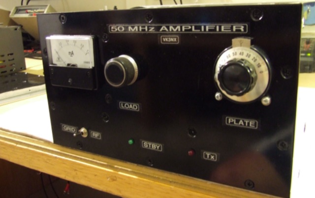 This project addresses the need for a 50 MHz Amplifier providing substantial power for Australian "Advanced Licensees" permitted to use 400W PEP in the 52-54 MHz band. In regions limited to 100W PEP due to TV channel usage, this initiative aims to enhance power output for transceivers with lower capabilities on the 6m band.
 -
 In this article, the current consumption for a selection of popular HF transceiver was examined to determine, via an on the field comparison, whether they were right for portable operation. The radios evaluated include the Yaesu FT-857D, Kenwood TS-590SG, Icom IC-7100, and Kenwood TS-480SAT. The measurements were taken beginning frok 5W in 5W increments up to 100W. The results showed that the Kenwood TS-590SG had the highest current use while the Yaesu FT-857D had the lowest. The current consumption of all radios increased as the power output increased.
 -
 The resource details the construction of a 433 MHz LoRa APRS iGate and a tracker, both built around _TTGO T-Beam v1.1_ microcontroller boards. Each board integrates an OLED screen, WiFi, GPS, and an SMA antenna connector, powered by an 18650 3.7 V lithium-ion battery or microUSB. The iGate operates on 433.775 MHz, with its status verifiable on aprs.fi, demonstrating practical implementation of LoRa-based APRS solutions. The methodology involves programming the modules using Visual Studio Code with the PlatformIO plugin. This process loads the necessary firmware and a JSON configuration file, which includes the operator's callsign and WiFi credentials for the iGate. The guide emphasizes the ease of programming and provides specific steps for configuration. Initial testing of the iGate and tracker, including smart beaconing configuration, is documented. The low power output of approximately 200 mW from the LoRa board's transmitter is noted, with suggestions for range extension through improved antennas or RF amplification. The author, N4MI, plans to deploy a higher-gain 70cm antenna for the iGate.
 -
 Learn how to build a simple transmitter called the 'Easy Ten' that can be easily heard at a distance of 10 miles using a random length wire antenna thrown into a tree. This article focuses on working with frequencies in the 3.5 and 7 MHz range without the need for complex setups like coax lines or baluns. The author shares their experience of making contacts across the Pacific Ocean and the United States using just one watt of output power and simple antennas. Discover how to optimize signal output using a homemade level meter made from a DC microameter and a germanium diode.
 -
 Integrating a _Software Defined Radio_ (SDR) into an existing ham radio setup involves connecting it with a standard transceiver (TRX), power amplifier (PA), and antennas. The core component is a splitter box that facilitates the connection between the TRX and the SDR, allowing for simultaneous operation without modifying existing equipment. In receive mode, the splitter ties the antenna inputs of both the TRX and a direct conversion receiver (DC RX) together. During transmission, the DC RX input is grounded via a fast telecom relay controlled by the transceiver's -SEND signal, incorporating a 10ms delay for safety. The splitter box includes a 3.7 dB input attenuator for impedance matching and acts as a protective fuse for the DC RX input. Ground loops are mitigated using common mode balun transformers, while the DC RX input is insulated with a broadband transformer. An audio switch box complements the setup, enabling users to listen to either the main transceiver, the SDR output, or both simultaneously. This configuration ensures noise immunity and safety, with the splitter housed in a screened box made from PCB material. On-air tests, such as the CQ WW 160m CW DX Contest, demonstrate the system's effectiveness, showcasing the SDR's ability to handle crowded band conditions with superior selectivity and dynamic range. The SDR's narrow bandwidth filters and waterfall display provide significant advantages, allowing operators to detect weak signals amidst strong interference. The integration of SDR with conventional radios offers enhanced operational flexibility and performance in challenging environments.
 -
 The FT101ZD DDS VFO project replaces the original VFO in the Yaesu FT101Z/ZD rigs with an AD9850 DDS module, providing enhanced frequency control. It uses the original optical encoder and clarifier for compatibility, with a custom 6V power supply modification. The project includes selectable step sizes, a frequency save function, and works with both RX and TX modes. The design involves mechanical and electronic modifications, including SMD components and a custom PIC processor. Calibration ensures accurate frequency output, with further improvements under consideration.
 -
 Official English Brochure by ICOM of the IC-7760 HF and 50 MHz 200W Power output, transceiver. PDF File
 -
 KISS703 is a 703 Hz narrowband digital mode for amateur radio, designed for simple, low-power operation without computers. A 500 Hz pilot tone ensures frequency alignment, replaced by unique tones for 37 symbols (letters, numbers, space). Built from common discrete components, it draws about 40 mA at 12 V, ideal for SOTA/IOTA use. The receiver uses amplification, wave shaping, and a pulse-counting frequency meter for manual decoding via a calibrated meter. Transmitter and receiver calibration involves marking meter positions for each tone, enabling fully self-contained messaging with minimal hardware in portable or fixed operations.
 -
 A dual insert microphone design for the Icom IC-7300 transceiver utilizes a **Besson BZ2400 M4 Rocking Armature** insert for frequencies from 500 Hz to 3 kHz, exhibiting a rising response of approximately 11 dB. A generic Electret Condenser insert, powered by the transceiver's microphone line, covers the low-frequency range from 100 Hz to 500 Hz. A Low Pass Filter is incorporated after the Electret insert to prevent frequency overlap, and a pre-set potentiometer (VR1) adjusts the low-frequency response, balancing the output of both inserts. The design emphasizes a "Close Talking" arrangement and addresses audio "colorization" by housing the Besson insert in a thick rubber holder with a foam boot, separate from the circuitry, with the Electret insert also wrapped in a foam boot. Critical importance is placed on using the correct BZ2400 M4 insert with 12 holes in its face plate. The frequency response table for the BZ2400 M4 insert shows 0 dB at 500 Hz, rising to +11 dB at 3000 Hz, while the Electret insert with the Low Pass Filter provides 0 dB at 100 Hz, rolling off to -9 dB at 500 Hz and -50 dB at 3000 Hz. This combination ensures a broad, balanced audio spectrum for SSB operation. The project includes a circuit diagram, a comprehensive parts list detailing components like a 1 Henry iron-cored inductor (L1) and various capacitors, and a board layout within the metal tube. The completed unit provides a tailored audio profile for the IC-7300, enhancing transmit audio quality.
 -
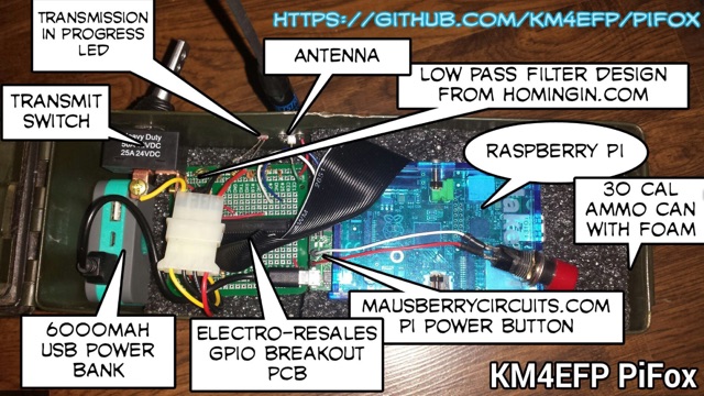 Raspberry pi powered fox hunt transmitter. pifox is a script written by KM4EFP to configure, control, and deploy a Raspberry Pi as a fox hunt transmitter. No external radio needed use your Pi's gpio output as a radio transmitter.
 -
 The project details the construction of a small, portable **CW decoder** built around an Arduino Nano and an LM567 tone decoder circuit. It integrates an OLED display for output and is powered by a 1200 mAh Li-Po battery. The Arduino Nano is programmed with a modified version of the OST Morse Box firmware, originally based on Budd, WB7FHC's work, provided as a HEX file for flashing. The LM567 output connects to Arduino pin D2, while pins A6 and A7 are grounded due to the absence of potentiometers, simplifying the circuit. Standard I2C connections are used for the OLED: SDA to A4 and SCL to A5. The entire assembly, including the Arduino, OLED, and decoder circuit, is mounted on a perfboard to fit precisely within an old cassette tape box. This design emphasizes portability and compact form factor. Parameters for the decoder can be adjusted using a dedicated Windows Control program, offering flexibility in operation. The resource provides practical insights into adapting existing firmware for specific hardware constraints and achieving a self-contained, battery-powered **Morse code** decoding solution.
 -
 Twenty 1-watt carbon film resistors are configured in parallel to construct a 50-ohm **dummy load** for amateur radio applications. The design incorporates a heatsink for thermal dissipation and an **SO-239 connector** for RF input, making it suitable for QRP operations. This budget-friendly project details component selection, soldering techniques, and mounting procedures, achieving a continuous power rating of 10 watts and intermittent handling of up to 100 watts across HF and VHF frequency ranges. The resource provides a step-by-step guide for assembly. This construction offers an economical solution for essential shack tasks such as antenna tuning, transmitter testing, and SWR meter calibration without radiating an RF signal. The utilization of readily available components significantly reduces the overall build cost compared to commercial alternatives, providing radio amateurs with a functional and reliable test accessory. While specific VSWR measurements are not provided, the design prioritizes practical utility for low-power transceiver diagnostics and general RF experimentation.
 -
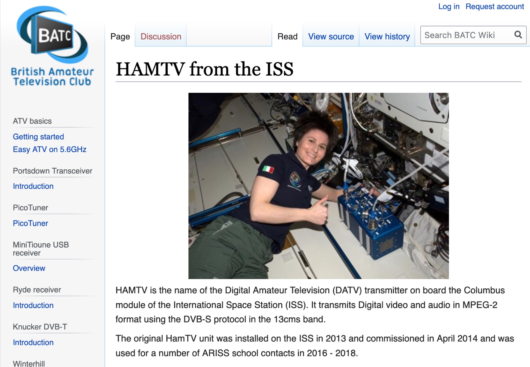 Learn about the HAMTV Digital Amateur Television (DATV) transmitter on the International Space Station (ISS), transmitting video and audio in MPEG-2 format using the DVB-S protocol. Discover its history, installations, failures, and repairs, as well as the current status and live video feed. Explore the technical details and challenges of the HAMTV transmitter, including power output, polarization, and antenna location. Find recordings of previous transmissions and understand the potential signal reflections caused by various ISS components. Stay updated on the latest developments and activities related to HAMTV from the ISS.
 -
 After years of reliable performance, a 26-year-old Icom 706MK2G exhibited an unusual deviation during FM transmission, with the actual frequency being 10kHz off from the displayed frequency. Additionally, the power meter showed a sharp dip during transmission. Upon investigation, it was discovered that the FM VCO voltage adjust variable had become dirty and sluggish over time. By adjusting the variable capacitor and cleaning it with switch cleaner, the issue was resolved, restoring stable power output and accurate frequency transmission.
 -
 The **5-Port 12 Volt DC Power Strip Kit (Rev 4)** offers a practical solution for managing shack power distribution, providing one input and five fused outputs. All connections utilize the ubiquitous Anderson PowerPole connectors, a standard for many amateur radio operators, ensuring a clean, organized, and safe way to power multiple 12 VDC transceivers and accessories from a single source. This design mitigates the common issue of tangled wires and overloaded connections in a typical ham shack. Rated for a maximum current of 20 Amps at 12 VDC, the strip incorporates an integrated LED to indicate when external power is applied. Each output is individually fused, a critical safety feature that protects connected equipment from overcurrent conditions without affecting other devices on the strip. This level of protection is essential for preserving sensitive radio gear during operation. Assembly requires basic soldering skills and hand tools, with a high-power soldering iron and wide chisel tip specifically recommended for best results. The kit's compact dimensions of 4.13" x 1.78" allow for flexible mounting via screw holes, making it suitable for various shack configurations and portable operations.
 -
 The project details the construction of a GM3OXX OXO transmitter, designed to accommodate **FT-243 crystals** using 3D-printed FX-243 holders from John KC9ON. It presents specific frequency adjustments, noting a 7030 KHz HC-49/s crystal could be tuned from 7029.8 KHz to 7031.7 KHz with an internal 45pF trimmer capacitor. The build incorporates a modified keying circuit to prevent oscillator run-on key-up and includes a TX/RX switch for sidetone via a connected receiver, with the transmitter output routed to a dummy load on receive. Practical construction aspects are thoroughly covered, including the process of cutting a rectangular opening in a diecast enclosure for the FT-243 socket and the selection of a **low-pass filter** (LPF) based on the QRP Labs kit, derived from the W3NQN design. The author achieved approximately 800mW output power from a 14.75V supply, measured with an NM0S QRPoMeter, using a 16.5-ohm emitter resistor in the 2N3866 final stage. The article also touches upon the potential for frequency agility across the 40M band using multiple FX-243 units with various crystals. The narrative includes a brief diversion into Bob W3BBO's recent homebrew projects, such as his Ugly Weekender MK II transceiver, highlighting the enduring appeal of classic QRP designs. The author reflects on the personal satisfaction derived from building RF-generating equipment, irrespective of DX achievements, and shares experiences of making local contacts with the 800mW OXO transmitter on 40 meters.
 -
 The Gemini Amplifier Remote Control software operates on Windows 7 and above, facilitating remote management of the Gemini HF-1K and DX-1200 amplifiers. Users connect via Ethernet, configuring the amplifier's IP address through the front panel. The software allows seamless band and antenna selection, saving settings for each band without requiring transmission. Integration with _OmniRig_ from Afreet Software, Inc. enables automatic band adjustments based on the radio's frequency changes. Users can configure serial or virtual serial connections, with tracking options accessible through the ribbon bar. The software supports speech functionality, enhancing accessibility for operators. Firmware updates, such as version 2.5Ee, introduce features like background datalogging and power output control, uploaded via FTP. Version 1.2.0 allows users to offload internal parameter data for support purposes. The firmware upload process requires the amplifier's IP address and port 21, taking approximately 90 seconds. Users are encouraged to upgrade to the latest firmware for improved performance and remote diagnostics.
 -
 The article details the repair of an Elecraft K3 transceiver experiencing an "ERR 12V" issue, causing reduced output power. The problem, common in these units, stems from inadequate pin strips carrying high DC current to the PA unit, leading to overheating and poor conduction. The author identified the faulty connectors and implemented a bypass using existing PCB pads, effectively rerouting the power and resolving the error. This straightforward fix highlights the importance of robust electrical connections in high-current applications, restoring the K3's full functionality.
 -
 This online project documentation details the construction of a hands-free microphone interface unit designed for _mobile_ amateur radio operation. The curriculum covers the integration of electret microphone elements with amateur radio transceivers, specifically addressing **VHF** band communication. It outlines the circuitry for a switch box that provides an interface between various radio models and microphone types. The guide specifies the inclusion of a **1750 Hz** tone-burst generator for accessing amateur radio repeaters, an operational protocol for many VHF systems. Design considerations include the reduction of ambient vehicle noise through an adjustable audio input level control. The project provides schematics and wiring diagrams for connecting the interface unit to specific amateur radio transceivers, including the Yaesu FT-817. It addresses the selection and adaptation of readily available electret microphone and earpiece assemblies, initially sourced from mobile phone accessories, and later from dedicated headset units. The design incorporates a control mechanism for radio functions, enabling hands-free operation during _mobile_ excursions. Circuit details cover power supply considerations for the electret microphone and signal routing for both transmit audio and received audio monitoring. The documentation specifies component selection for the switch box, ensuring compatibility with common amateur radio microphone input impedances and output levels. This includes considerations for PTT line switching and audio path isolation. DXZone Focus: Online Project Documentation | Hands-Free Mobile Microphone Interface | Electret Microphone Integration | 1750 Hz Tone-Burst Generation
 -
 This resource details **cooling modifications** for Ameritron AL82, AL1200, and AL1500 HF amplifiers, specifically addressing heat issues encountered during high-duty-cycle digital mode operation. The author, WD4NGB, observed excessive heat in the tank area and band switch on an AL82, attributing it to insufficient exhaust over the 3-500 tubes and a complete lack of exhaust over the tank area. The modifications aim to prevent common failures such as damaged band switches and deformed insulating materials by increasing airflow and exhaust area. The page describes adding five holes to the chassis for enhanced cooling to the band switch and tank area, alongside enlarging the exhaust area over the inner 3-500 tube and the tank area on the amplifier cover, utilizing expanded metal for safety and RF shielding. The original cover featured 26.25 square inches of exhaust; the modified version significantly increases this to 48.5 square inches over the tubes and introduces an additional 15 square inches over the band switch. These changes are intended to resolve heating problems encountered during heavy, 100% duty cycle use in modes like RTTY or long SSB contests, which typically generate substantial heat. The article also discusses upgrading to a higher output fan, such as the G2E085-AA05-21, and modifying tube sockets for improved airflow and reduced back pressure, citing Tom Rauch (W8JI) of CTR Engineering as a source for parts.
 -
 The W6PQL 23cm Beacon Project describes a **1296 MHz** beacon designed for microwave propagation studies and equipment testing, capable of 30 watts output. It utilizes a PIC 16F628A microcontroller to generate CW and FSK keying for a crystal oscillator, followed by a series of frequency doublers and triplers to reach the target frequency. The final power amplification stage employs a Mitsubishi M57762 module, providing a robust 10-watt RF output. The design emphasizes stability and reliability for continuous operation, with the microcontroller code, written in assembly, provided for customization of the beacon's callsign and message. Originally located in CM97am and aimed at 140 true, the beacon used four 4-foot Yagis stacked vertically for a total ERP of 3kW. The article includes schematics, parts lists, and construction notes to guide builders, along with antenna pattern measurements. Although the beacon itself is no longer in service as of August 2010, the detailed documentation remains a valuable reference for amateur radio operators interested in building similar **microwave** projects or understanding beacon operation.
 -
 The Anytone AT-D878UVII Plus, a dual-band transceiver, supports both Analog and DMR modes, providing versatile communication options for amateur radio operators. This model is complemented by the Anytone AT-6666 Pro, which delivers a substantial 80W output, catering to users requiring higher power for their radio operations. For mobile and off-road applications, RadioSmart Solutions features a 4x4 Mobile Radio Package Deal, which includes the RTS DV-2135s Mobile Two-Way Radio. This package is specifically designed for reliable communication in challenging environments, often encountered during off-road adventures. An _RSS Rugged Off-Road Antenna_ is also available, engineered to withstand harsh conditions and ensure robust performance. The product range addresses the needs of individuals seeking durable and functional communication solutions for both general amateur radio use and specialized mobile deployments.