Search results
Query: voltage
Links: 118 | Categories: 2
-
 When building antennas for the Wifi band (Like the 8dBi omni), a need for an easy way to check the antennas arose. A Voltage Standing Wave Ratio (VSWR) meter useable at the 2.4GHz band is however, hard to find.
 -
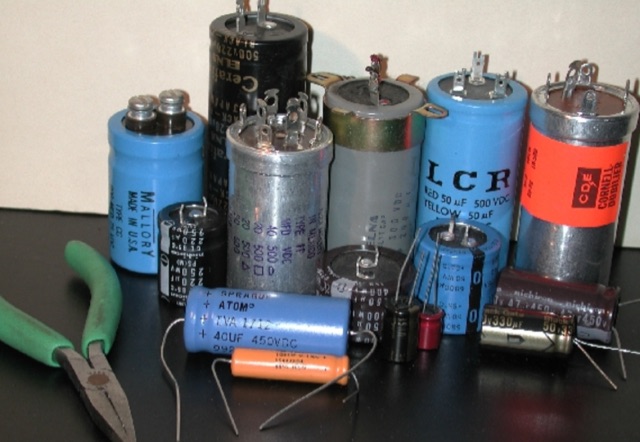 For low voltage applications, like cathode bypass capacitors, most vintage types have an axial configuration, which is less common today but still available. Electrolytic power supply caps likely constitute the single worst liability in old audio, radio and test equipment. Rap about Electrolytics, Reforming, Chassis-Mount Replacements, Under-Chassis Installation, Rebuilding Capacitors
 -
 Antennas for low-power operation resemble those for 100W use. Minor adjustments, like capacitor voltage ratings, may apply, but basic principles persist. Portable antennas, notably Backpack Antennas for weight-conscious setups, hold relevance beyond QRP. While some antennas function acceptably at higher power, efficiency issues arise at QRP levels. Testing antennas at 100W exposes weaknesses, particularly in tuners, crucial for efficient QRP operation.
 -
 Andrew Georgakopoulos, SV1DKD, modeled the End-Fed Half Wave (EFHW) antenna using MMANA-GAL software. He evaluated the EFHW-8010-2K from Myantennas.com for field operations, comparing it to random wires, OCFD, and dipole antennas. His results showed similar performance to OCFD, confirming EFHW's practical feeding advantage but with potential high-voltage risks at the feed point
 -
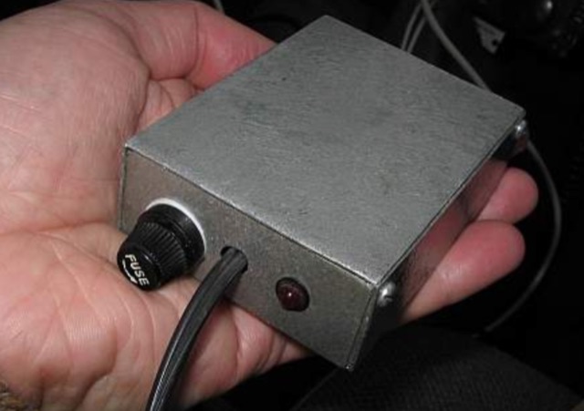
 Four _Headway 38120_ LiFePO4 cells form the core of an 8AH 12V battery pack, designed for reliable emergency and field power in amateur radio operations. These batteries offer significant advantages over traditional lead-acid types, including a lifespan up to **10x** longer in charge/discharge cycles, lower internal resistance for faster recharging, and a flatter discharge curve that maintains voltage stability during use. Their inherent safety, being a flame-retardant technology, makes them a preferred choice for portable applications. Proper configuration, including parallel/serial setups, and careful charging/discharging protocols are crucial for maximizing battery life. Each cell has a nominal voltage of 3.2 volts, with a maximum charge voltage of 3.65 volts. A Battery Management System (BMS) is highly recommended to prevent overcharging or deep discharging, safeguarding the cells. The project emphasizes safety, noting the batteries' high short-circuit capacity of **200 AMPS** and the critical importance of incorporating an inline fuse between the battery pack and the load. Components like the battery holder, buss bars, and a suitable case are also detailed.
 -
 Well, firstly the 12 Volt source will typically vary anywhere from 11 Volt to 15 Volt, and then a battery needs a controlled charge current and voltage, which cannot result from connecting it directly to a voltage source.
 -
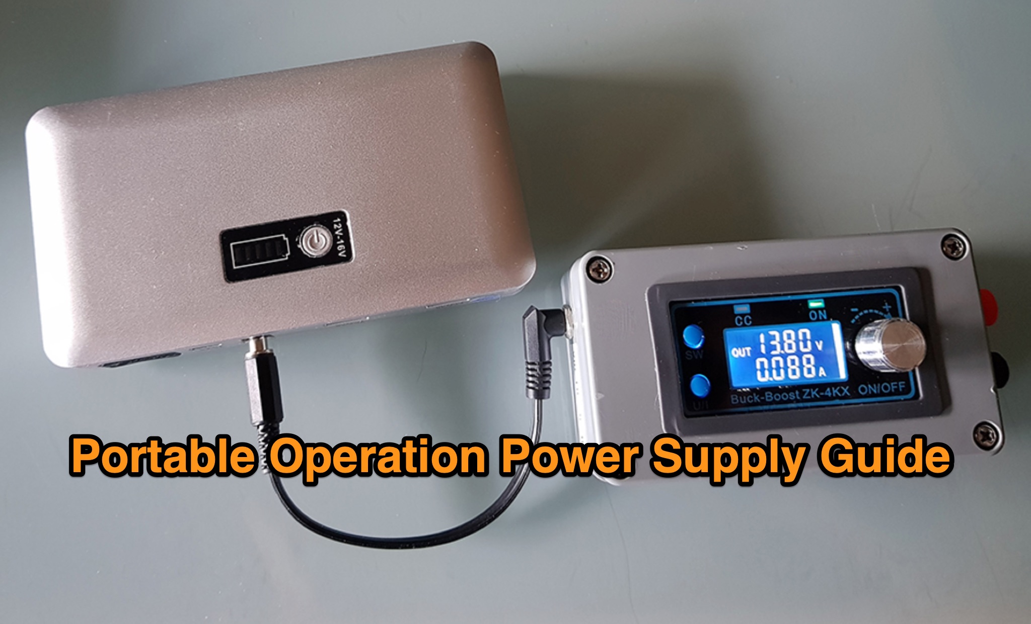 The _Icom IC-705_ portable operation power supply guide details the use of a car battery jump starter and a step-up/down converter for field power. It examines various power supply types, including LiFePO4 batteries, lead-acid batteries, and supercapacitors, discussing their respective advantages and disadvantages for QRP and portable setups. The resource emphasizes practical considerations such as capacity, weight, discharge rates, and charging methods crucial for reliable off-grid operation. The article compares the energy density and cycle life of different battery chemistries, noting that LiFePO4 batteries offer significantly more cycles (e.g., **2000-5000 cycles**) compared to lead-acid batteries (e.g., **300-500 cycles**). It also touches upon the integration of solar panels for recharging and the importance of proper voltage regulation to protect sensitive radio equipment, providing insights into maximizing operational time during DXpeditions or POTA activations.
 -
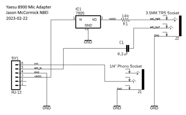 Explore the process of creating a custom adapter for the Yaesu FT-8900 radio with a non-standard mic port. The article guides users through understanding the reversed pin-out of the RJ-12 connector on the 8900, providing a detailed circuit for adapting the voltage for electret-based mics. With a list of required parts and construction tips, this DIY project ensures seamless compatibility with standard electric headset mics.
 -
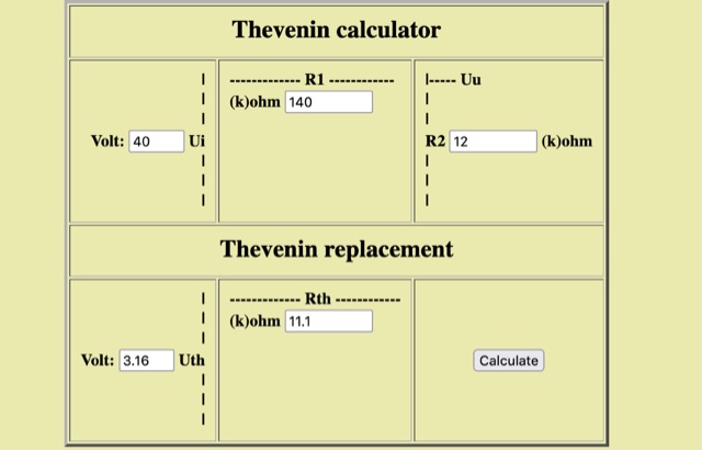 The Thevenin equivalent simplifies a complex circuit into an equivalent circuit with a voltage source and resistor for easy analysis of voltage and current at any point in the circuit. Use this online Thevenin calculator
 -
 The DIY Power Meter project utilizes the _INA226_ high-side power monitoring chip, paired with an ATtiny85 microcontroller, to measure voltage, current, and power, displaying the results on a 128x32 OLED screen. The INA226 communicates via an I2C interface and is programmed with a calibration factor based on the shunt resistance and current register LSB. The project is designed to handle a maximum current of 500mA using a 0.16ohm shunt resistor, which can be adjusted to a 0.2ohm resistor, reducing the full-scale current range to 409mA with a resolution of **12.5uA**. The shunt resistor dissipates only 33mW at maximum current, making 1/4 watt resistors suitable for the setup. The PowerMeter.ino sketch configures the shunt resistance and maximum design current, automatically calculating the calibration factor. The project can be prototyped on a breadboard using an Arduino Uno, employing the Wire library for INA226 and OLED communication, and the u8g2lib library for the OLED display. For the ATtiny85 version, the Adafruit-TinyWireM and Tiny4kOLED libraries are used. The power meter is independently powered by a 3V CR2032 cell, with power switching options including manual switches or DC switched jacks. The low-side n-channel MOSFET switch configuration is tested but introduces voltage drop issues, making manual switching a more reliable option until a suitable DC switched jack is found. DXZone Technical Profile: INA226 | ATtiny85 | OLED Display | Power Meter
 -
 Detecting stray RF voltages on station grounds, chassis, and interconnecting cables is crucial for preventing program and hardware failures in the shack. This article details the construction and application of an LED RF V-probe, which offers significantly higher sensitivity compared to conventional neon lamp indicators. The probe leverages two specific properties of modern red LEDs: their ability to glow at microampere currents and their rectification capability at frequencies up to tens of megahertz. The design features a simple circuit with two LEDs, allowing for indication of both positive and negative RF voltage half-waves. The minimum detectable RF voltage is approximately 2 V, a substantial improvement over the 40-60 V threshold of neon bulbs. The resource illustrates the probe's physical construction on a PCB and provides a direct comparison demonstrating its superior sensitivity in detecting RF fields near a coil. Two operational modes are described: a non-contact mode for high RF voltages (above 15-20 V) and a direct-contact mode for measuring lower RF voltages, with a safety caution for the latter. Practical examples show the probe's use in analyzing RF voltage distribution across a radio station setup at 1.84 MHz and 24.9 MHz, revealing insights into common-mode current issues and the effectiveness of mitigation strategies like adding radials.
 -
 This project outlines a simple Lead Acid/SLA battery monitor, designed to alert users when battery voltage falls below 10.6V. The monitor, based on a PIC16F1827 microcontroller, checks the voltage of up to five batteries and triggers an alarm if any drop too low. The system operates in various modes, including self-test, monitoring, and alarm. This updated version improves upon the original 1999 design, offering a more modern microcontroller and extended functionality for workshop use, with minimal impact on battery charge.
 -
 This article provides a comprehensive introduction to the decibel (dB), its logarithmic nature, and its applications in power, voltage, and antenna gain calculations. It explains how dB simplifies comparisons in electronics, telecommunications, and audio perception. The author clarifies key mathematical concepts, including power ratios, voltage doubling, and absolute levels like dBm and dBV. The discussion on S-units and antenna system gain is particularly relevant for radio amateurs. Overall, this is an informative and well-structured guide to understanding and applying decibels in technical fields.
 -
 After years of reliable performance, a 26-year-old Icom 706MK2G exhibited an unusual deviation during FM transmission, with the actual frequency being 10kHz off from the displayed frequency. Additionally, the power meter showed a sharp dip during transmission. Upon investigation, it was discovered that the FM VCO voltage adjust variable had become dirty and sluggish over time. By adjusting the variable capacitor and cleaning it with switch cleaner, the issue was resolved, restoring stable power output and accurate frequency transmission.
 -
 The page features a spreadsheet that calculates power in watt and dBm based on voltage and impedance, power in dBm with a given power and impedance, voltage in millivolts with a given power and impedance, and more. It also converts between millivolt, microvolt, volt, watt, and milliwatt. Useful for hams looking to accurately calculate power and voltage values for radio equipment. Last updated in December 2014.
 -
 The **Yaesu FRG-100** shortwave receiver, introduced in 1992, operates across a frequency range of 50 kHz to 30 MHz, accommodating AM, LSB, USB, and CW modes, with an optional narrow-band FM capability. Its physical dimensions are 238 x 93 x 243 mm, with a weight of 3 kg, making it suitable for both portable and fixed station deployments. Power options include standard mains voltage or 12VDC, providing operational flexibility for diverse listening environments. The front panel integrates a manual tuning knob, an analogue signal strength meter, and an LCD display that provides critical information such as frequency, operating mode, memory channel, and time. Users can configure various operational parameters, including tuning steps and bandwidth filters, to optimize reception for specific signals. This review highlights the FRG-100's straightforward interface and its utility for shortwave listening enthusiasts. The design emphasizes user-friendly adjustments for settings, which contributes to its appeal among those interested in general coverage reception.
 -
 The Pressure Paddle V2.0 simplifies the original 2019 design by using MOSFETs’ unique properties for reliable, minimalistic switching. When pressure sensors detect a press, they reduce resistance, activating the MOSFET and lowering voltage until it stabilizes at the MOSFET’s threshold. This ensures consistent “key down†signals for the transceiver. Compatible with 3-5V logic systems, the circuit operates independently of pull-up resistor size. The PCB is lightweight, easy to assemble, and can be packaged in heat shrink or mounted. This version maintains durability with fewer components and flexible packaging options.
 -
 This online construction guide details the assembly of a signal generator specifically for the **13cm band** (2.4 GHz). The curriculum focuses on the integration of a Voltage Controlled Oscillator (VCO), specifically the ROS-2400, to produce a stable RF signal. The resource outlines the necessary components for frequency generation and output, including the use of a Mini-Circuits MMIC amplifier for signal conditioning. The construction protocol involves configuring the ROS-2400 VCO to operate within the 2.3 GHz to 2.45 GHz range, ensuring frequency coverage for amateur radio _microwave experimentation_. The guide specifies the output power level, approximately 70mW, directly from the MMIC stage, indicating its application as a low-power instrumentation source rather than a transmit-capable device. This project provides a practical example of constructing a dedicated test instrument for microwave frequency measurements and system alignment on the **13cm band**. DXZone Focus: Construction Guide | 13cm Signal Generator | VCO Integration | Microwave Experimentation