Search results
Query: yagi antenna for 8 mhz
Links: 132 | Categories: 3
-
 Stacking yagi antennas for 50 Mhz band article by by Zaba, OH1ZAA/NN0Y
 -
 Antennas for the 1296 MHz based on the construction plans of some Yagis 35 elements by DL6WU, F9FT, DJ9YW. These antennas features a boom of about 3 m and gives a gain of about 17.8 dBd
 -
 A collection of 450 MHz Cheap Yagis that have proven great portable operations, back-packing and transmitter hunts, and are something inexpensive you can throw up in the attic for that weak repeater
 -
 A short 3 element LFA Yagi for 50MHz with a 1.94M boom. This antenna has been designed in order to minimise the upward and downward lobes typically seen the the EL plane on Yagi antennas.
 -
 10 Elements Cross-Yagi Antenna for 433 MHz. The base of the 10el antenna is the recalculated RA6FOO antenna.Circular polarization is realized - by a phasing quarter-wave line, matching of horizontal and vertical polarization antennas
 -
 This 10 meter antenna is right out of the ARRL Antenna Book. There are 5 elements on a 24 feet boom and it performs well from 28.0 to 28.9 MHz.
 -
 A Lightweight 2m Yagi for SOTA. The boom is 20mm PVC electrical conduit and the elements are 2.4mm aluminium TIG welding rod. The antenna is carried as a single length of conduit with the elements stowed inside the boom, sealing them in with a bung. The driven element is connected directly to 50 Ohm coax with a BN-43-202 balun core to decouple the coax shield.
 -
 Construction of an antenna for experimental satellite communication, 8el. (435 Mhz) x 4el. (145 Mhz) Satellite Yagi crossed. No difficulty to built this antenna. Except the gamma match. that requires a little more attention
 -
 A homebrew 13 elements yagi antenna for two meters band. These project includes two model of the same antenna with a 6 and 7 meter boom length. Detailed pictures and nec files are available for download
 -
 1260 MHz yagi antenna for ATV with a total Bandwidth (3 dB) 1240-1280 MHz and 10 dBd gain
 -
 This multiband transverter project features power output at 13,8V 50MHz 15W, 70MHz 10W, second harmonic < 65dBc. Single N connector of antenna, suitable for a dual band Yagi. Article include Block Diagram for Dual Transverter and low pass filters
 -
 This project involves constructing a dual-band Moxon antenna, optimized for ham radio enthusiasts, with functionality on both the 10-meter and 6-meter bands. The antenna is designed to operate using a single 50-ohm feedpoint, acting as a mini-beam on 28 MHz (10 meters) and as a 2-element Yagi on 50 MHz (6 meters). Performance-wise, it offers a 4.0 dBd gain on 10 meters and 4.3 dBd on 6 meters, with impressive front-to-back ratios of 30 dB and 11 dB, respectively. Builders like Aleks (S54S) and Marcio (PY2OK) have successfully brought this design to life using the provided specifications. Aleks noted that bending the corners of the structure proved especially useful during assembly. The project comes with a detailed parts list, highlighting the use of aluminum tubes with different diameters and lengths to form essential components like the reflectors and radiators. For those looking to fine-tune the antenna, adjustments can be made by altering the length of certain parts that fit into larger tubes. The feeding system is equipped with a balun to accommodate different power levels, making the design versatile enough to handle outputs of either 300 watts or 1 kilowatt.
 -
 Paul McMahon presents a compact VSWR meter designed for QRP portable use, ideal for SOTA operations with rigs like the FT817. The device, constructed from readily available components, employs a simple resistive bridge for wideband performance from 1.8MHz to 52MHz, with diminishing accuracy at higher frequencies. Key features include no need for external power, simple calibration, and operation with low power levels. The design, detailed with parts lists, schematics, and construction guidelines, ensures a 2:1 worst-case VSWR to protect transceivers during antenna matching. Calibration points are set for accurate VSWR readings at various loads.
 -
 144MHz 2m Portable Yagi VHF Beam Antenna. This page contains construction details on a 2 metre 144MHz VHF Yagi beam antenna, designed for portable use.
 -
 In this article the author describes his personal experience on some antennas for 50 MHz he tested on the field, the six meter Dipole, Vertical, Moxon, a 3 element Yagi and an Omniangle antenna.
 -
 This is a design based on the QuickYagi 4 software by WA7RAI with some changes for practical reasons. The beam uses 6.5 metres of standard 25mm square boom, 12mm diameter elements without tapers. The actual boom length used is 6.3 metres and all parts are readily available.
 -
 This article describes the phases for the construction of a Yagi antenna. The calculations of the parameters are made using 4NEC2 software. This type of antenna is used for transmissions and receptions of electromagnetic waves. The project shown here refers to the frequency of 433.92 MHz.
 -
 This six element LFA Yagi for six meters has a 1.5 inch square boom with a 1.5 inch secondary boom beneath the first. This ensures the 7.3 metre long boom will not sag and will not require any guying. This antenna has 12.3 dBi Gain and just over 23dB F/B.
 -
 This document provides a detailed guide on constructing and mounting a folded dipol for the 146 MHz frequency in a vertical configuration to be used in Yagi antennas. The step-by-step instructions and diagrams included make it easy for hams to build and set up this type of antenna. Understanding and implementing this design can enhance the performance of radio communication for Amateurs operating in the 2-meter band. Whether you are looking to improve your signal strength or experiment with antenna designs, this resource offers valuable insights and practical information.
 -
 This DIY guide details constructing a 5-element Yagi antenna for VHF frequencies. Yagi antennas offer directional signal transmission/reception compared to omnidirectional ones. The guide covers material selection (aluminum, screws, etc.), design using software or formulas, and step-by-step assembly including cutting elements, drilling holes, and attaching the coaxial cable. While calculations are provided for a 146 MHz design, adjustments are necessary for different frequencies. Safety precautions and potential result variations are emphasized.
 -
 Showcasing German engineering, ANjo Antennen develops and manufactures a diverse portfolio of amateur radio and commercial antenna products. Their offerings span a wide frequency range from 1.8 MHz to 3000 MHz, emphasizing electrical and mechanical precision for longevity. The company actively participates in events like FUNK.TAG Kassel, providing opportunities for direct engagement and order pickup. ANjo's product line includes high-performance **Yagi antennas** optimized for Tropo and EME, along with multi-stacked Quad antennas designed for contest operations, featuring wide horizontal and narrow vertical beamwidths. They also produce circularly polarized satellite antennas, some with switchable LHCP/RHCP, leveraging their commercial satellite antenna expertise. Beyond amateur applications, ANjo provides flexible, custom antenna solutions for commercial sectors such as BOS, EMC measurements, and telemetry. Their commitment to quality is evident in the Premium-Line antennas, which utilize **1.4301 (V2A) stainless steel** for mast clamps and connectors, ensuring durability and corrosion resistance. They also offer end-fed HF multiband wire antennas, known for their compact footprint and discreet installation.
 -
 This project introduces the Loggi, a hybrid antenna merging the wide frequency coverage of log-periodic dipole arrays (LPDA) with the high gain and front-to-back ratio (F/B) of Yagi antennas. Traditional LPDAs span broad frequencies with moderate gain and low VSWR, while Yagis provide high gain and F/B over narrow bands. By analyzing high-Tau LPDA designs, it was found they could nearly match the gain of VHF/UHF Yagis while maintaining excellent patterns, F/B, and front-to-rear ratios (F/R). Optimizing specific elements for target frequencies (e.g., 144.1 MHz) led to the Loggi, which uniquely features all driven elements without passive directors or reflectors. This design effectively functions as a narrowband optimized LPDA, with front elements acting like Yagi directors and rear elements like Yagi reflectors, thus enhancing gain and directional characteristics while retaining broad frequency versatility.
 -
 A home made project for a 7 element yagi antenna for the two meters band based on the DK7ZB original desing.
 -
 This is a plan for an optimized element UHF Yagi Antenna for UHF Bands featuring a 9dBd forward gain, a 13 dB front-back ratio, and a bandwith of 10 MHz on the 430-440MHz range.
 -
 This DIY Yagi costs less than 20 Dollars, and let you increase the performance of your connection. With this project you can build a better Yagi beam antenna resonant on 850MHz, a 8 element yagi directional antenna
 -
 Paul McMahon details the design and construction of a four-element Yagi antenna for the 50-52.5 MHz range, published in Amateur Radio Magazine (Dec 2011). The antenna, featuring a raised driven element and a capacitive/DC connection using copper strips, maintains consistent VSWR and performance despite two years of weather exposure. The design utilizes inexpensive plumbing conduit for the boom and provides detailed construction guidelines, parts lists, and performance analysis through 4NEC2 simulations.
 -
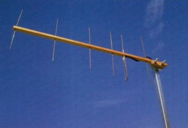
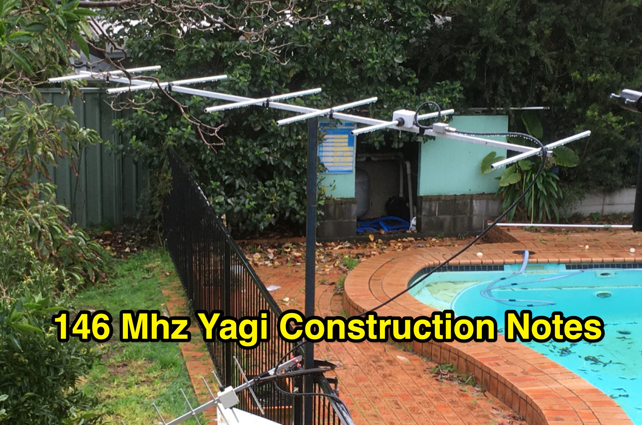 This PDF document contains construction notes for a Yagi antenna designed for the 146 Mhz frequency range. It provides detailed instructions and information on how to build the antenna, making it a valuable resource for hams looking to improve their radio setup. The document covers the materials needed, step-by-step construction process, and tips for optimizing performance. Whether you are a beginner or an experienced ham radio operator, these construction notes can help you enhance your antenna system for better communication.
 -
 Guide to constructing an effective antenna for 50MHz. Inspired by a design from Martin DK7ZB, the article emphasizes the importance of precise measurements and quality materials. With a 2.20m boom and careful assembly, the antenna promises excellent performance, resilience, and cost-effectiveness, making it ideal for six meter band operations.
 -
 This paper by Leif Asbrink (SM 5 BSZ) presents a practical approach to designing very high gain Yagi antennas, focusing on the "brute force" optimization method. The method, described in a previous article, ensures convergence independent of initial guesses. The paper provides detailed tables of element lengths and positions for Yagi antennas optimized for 144.1 MHz with a 50-ohm feed point impedance, aiming for minimal losses and high accuracy in comparisons.
 -
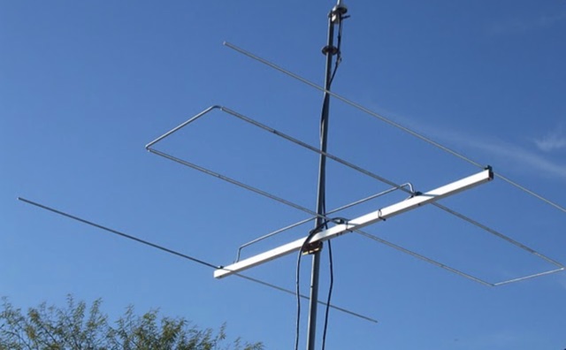
 145 MHz is the target frequency for this 2-meter Skeleton Slot Yagi Stack antenna project. The design focuses on feeding two stacked Yagi antennas using a skeleton slot radiator, which is a unique approach for VHF enthusiasts. The project details the construction process, including the loop tapered matching section for impedance matching, ensuring optimal performance. The use of specific components like the EH789 element holder and MB456 main mast bracket is highlighted, providing clarity on the assembly process. The construction utilizes 20x20 box aluminum bar for durability and precision. Key dimensions, such as the element length (ER-ED4) and main boom spacing (MM123), are meticulously outlined. This attention to detail aids in replicating the antenna design accurately. The downloadable PDF offers comprehensive instructions, making it accessible for amateur radio operators interested in VHF antenna construction. This project is particularly beneficial for those looking to optimize their 2-meter band operations. The inclusion of a skeleton slot radiator and loop tapered matching section demonstrates advanced techniques in antenna design, catering to both intermediate and advanced builders.
 -
 SAT filters ensure effective full-duplex satellite QSOs by mitigating interference between 145 MHz uplink and 435 MHz downlink signals. Custom coaxial and SMD-based filters address transmitter harmonic interference and improve receiver isolation, achieving over 70 dB suppression in the undesired band. Designed for simplicity, these filters maintain optimal VSWR and are housed in shielded brass enclosures. Practical implementations with Yagi antennas demonstrate compatibility with SDR systems, enabling seamless communication even in challenging satellite conditions, such as low-elevation passes and DX pile-ups.
 -
 The W6PQL 23cm Beacon Project describes a **1296 MHz** beacon designed for microwave propagation studies and equipment testing, capable of 30 watts output. It utilizes a PIC 16F628A microcontroller to generate CW and FSK keying for a crystal oscillator, followed by a series of frequency doublers and triplers to reach the target frequency. The final power amplification stage employs a Mitsubishi M57762 module, providing a robust 10-watt RF output. The design emphasizes stability and reliability for continuous operation, with the microcontroller code, written in assembly, provided for customization of the beacon's callsign and message. Originally located in CM97am and aimed at 140 true, the beacon used four 4-foot Yagis stacked vertically for a total ERP of 3kW. The article includes schematics, parts lists, and construction notes to guide builders, along with antenna pattern measurements. Although the beacon itself is no longer in service as of August 2010, the detailed documentation remains a valuable reference for amateur radio operators interested in building similar **microwave** projects or understanding beacon operation.