Search results
Query: 144
Links: 178 | Categories: 1
Categories
-
 This article provides a detailed guide on how to build a no holes roof mount for ham radio antennas. The author shares their design that can hold 2 masts and offers tips on installation. The mount is versatile and can handle small 144 Mhz or 432 Mhz beams, as well as small verticals. With adjustable angles and spacing, the mount can be customized to fit different roof types. Additionally, the author suggests affordable options for obtaining Dish antenna mounts. Overall, this DIY project offers a cost-effective solution for ham radio operators looking to mount antennas on their roofs.
 -
 Messi & Paoloni offers a range of RF coaxial cables, including the _Ultraflex_ series, specifically engineered for amateur radio applications. These cables feature advanced dielectric materials and high-density braiding, resulting in significantly reduced attenuation across HF, VHF, and UHF bands. For instance, the Ultraflex 7 exhibits a loss of only **2.5 dB per 100 feet** at 144 MHz, making it suitable for demanding DX and contesting operations. The company's product line also includes specialized connectors, such as N-type and PL-259, designed to maintain optimal impedance matching and minimize signal reflections. Each connector is precision-machined to ensure a secure, weather-resistant termination, crucial for outdoor antenna installations and long-term reliability. Messi & Paoloni emphasizes rigorous quality control, with all cables undergoing testing to ensure consistent performance and durability, supporting effective two-way radio communication.
 -
 Experimental Long Boom Antennas - CP, LPDA, multiband with several NEC Files for 50MHz 144MHz 222 MHz 432MHz but also 902MHz and 1296 MHz Antenna projects. Includes also for each antenna model, in a general comparison table each antenna characteristics including Directive Gain, G/T, E-F/R, H-F/R abd Boom Length. This is a great value comparison table of several commercial and home made VHF UHF antenna projects.
 -
 Constructing a directional antenna for VHF operations, particularly for 2-meter band contests or local communication, often involves balancing performance with ease of build. The Moxon rectangle, a compact two-element beam, offers a good front-to-back ratio and gain in a smaller footprint compared to a Yagi, making it suitable for portable or temporary setups where space is limited. This design typically uses a driven element and a single reflector, bent into a rectangular shape to achieve its unique radiation pattern. The article details the construction of a 2-meter Moxon antenna, specifically for 144 MHz, utilizing readily available materials like PVC pipe for the frame and copper wire for the elements. It outlines the dimensions for the driven element at 970mm and the reflector at 910mm, with a spacing of 140mm between them, and a 50mm gap at the element ends. The feedpoint is a direct 50-ohm connection, simplifying matching requirements. The project includes a parts list, a basic diagram illustrating the element layout and dimensions, and photographs of the completed antenna. The author notes the antenna's performance during a QRP contest, achieving contacts up to 100km with 5 watts, demonstrating its effectiveness for low-power VHF work.
 -
 A very essential j-pole antenna for 144 MHz. To adjust the SWR you will have to play with the 40mm distance between the coax feed and the braid inner conductor connection
 -
 A Lightweight 2m Yagi for SOTA. The boom is 20mm PVC electrical conduit and the elements are 2.4mm aluminium TIG welding rod. The antenna is carried as a single length of conduit with the elements stowed inside the boom, sealing them in with a bung. The driven element is connected directly to 50 Ohm coax with a BN-43-202 balun core to decouple the coax shield.
 -
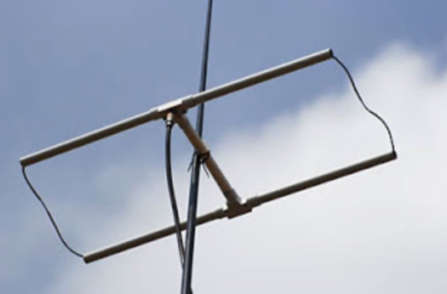
 This stacking offers a well known simple phasing technique. All elements can be fed in parallel by open wires provided that they are fed in phase. This can be achieved by twisting the open wire phasing-lines at 180 degrees.
 -
 A homebrew 13 elements yagi antenna for two meters band. These project includes two model of the same antenna with a 6 and 7 meter boom length. Detailed pictures and nec files are available for download
 -
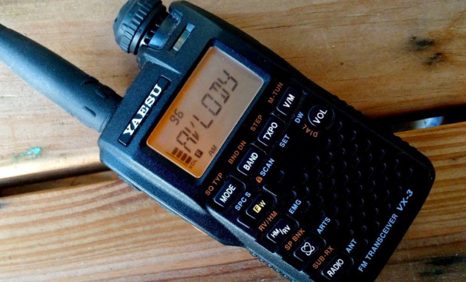 Review of Yaesu VX-3R 2 m/70 cm FM transceiver. Receives 0.5-999Mhz AM/FMN/FMW, Transmits 144-148 and 430-450Mhz VHF/UHF FM.
 -
 144MHz 2m Portable Yagi VHF Beam Antenna. This page contains construction details on a 2 metre 144MHz VHF Yagi beam antenna, designed for portable use.
 -
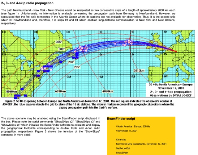 Thunderstorm effects on sporadic E propagation, Very long distance propagation in the 144 MHz band, Analysing the number of skips in multiple hop propagation
 -
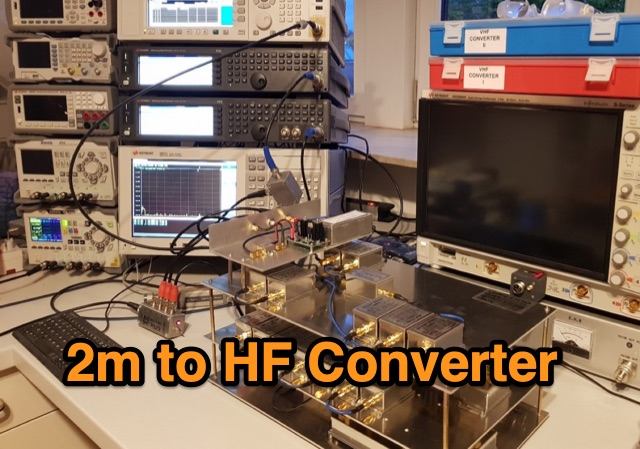 Ulrich L. Rohde N1UL conceived an outstanding 2m to HF receiving converter with specific requirements, including 144-148MHz to 28-32MHz coverage, low noise, high IP3, and a unique modular design. The design decisions emphasize modularity, absence of preselection, stability, and a passive mixer, showcasing Rohde's distinctive approach.
 -
 This project introduces the Loggi, a hybrid antenna merging the wide frequency coverage of log-periodic dipole arrays (LPDA) with the high gain and front-to-back ratio (F/B) of Yagi antennas. Traditional LPDAs span broad frequencies with moderate gain and low VSWR, while Yagis provide high gain and F/B over narrow bands. By analyzing high-Tau LPDA designs, it was found they could nearly match the gain of VHF/UHF Yagis while maintaining excellent patterns, F/B, and front-to-rear ratios (F/R). Optimizing specific elements for target frequencies (e.g., 144.1 MHz) led to the Loggi, which uniquely features all driven elements without passive directors or reflectors. This design effectively functions as a narrowband optimized LPDA, with front elements acting like Yagi directors and rear elements like Yagi reflectors, thus enhancing gain and directional characteristics while retaining broad frequency versatility.
 -
 A home made project for a 7 element yagi antenna for the two meters band based on the DK7ZB original desing.
 -
 The article describes a high-gain, compact beam antenna design for the 2-meter band (144-146 MHz). The NSH 4x4 Boomer is a 4-element antenna that is mounted on a 4-foot boom with an 8.2 dB gain, 1.2:1 SWR, and a front-to-back ratio of 18 db. It is designed for mobile operations and little area, making it perfect for field usage such as disaster management. The design employs regularly spaced parts with a straightforward gamma match for tuning, and the construction materials include a square boom and polished aluminum tubes. In local and portable tests, the antenna worked regularly, achieving contact distances of up to 15 kilometers.
 -
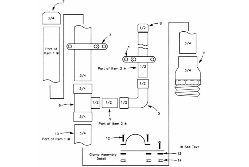 The All-Copper J-Pole Antenna Construction for 2 Meters document outlines a specific build methodology for a VHF base station antenna. It addresses common issues like dissimilar metal corrosion and feed line degradation often encountered with aluminum J-Pole designs, proposing an all-copper and brass solution with soldered connections for enhanced durability and electrical performance. This resource provides a comprehensive parts list in Table 1, detailing precise copper tubing lengths and other necessary hardware components. The design emphasizes DC grounding, which eliminates the need for insulating materials and simplifies installation, contributing to a robust and weather-resistant structure. Michael P. Hood, KD8JB, details an assembly process estimated to take approximately one hour, with total material costs projected under $15. The antenna's construction focuses on rigid copper tubing and fittings, ensuring long-term integrity for 144 MHz operation.
 -
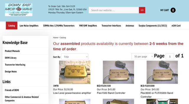 Manufacturer of 50MHz, 70MHz, 144MHz, 222MHz, 432MHz, 900MHz or 1.2GHz transverters and VHF UHF amplifiers
 -
 A detailed guide presents a simple 2-element quad antenna for 2m, offering ease of construction, portability, and efficient performance across the 144-148 MHz band. The design allows quick disassembly for storage and features adjustable polarization, making it ideal for various applications, including transmitter hunting and SSB operations.
 -
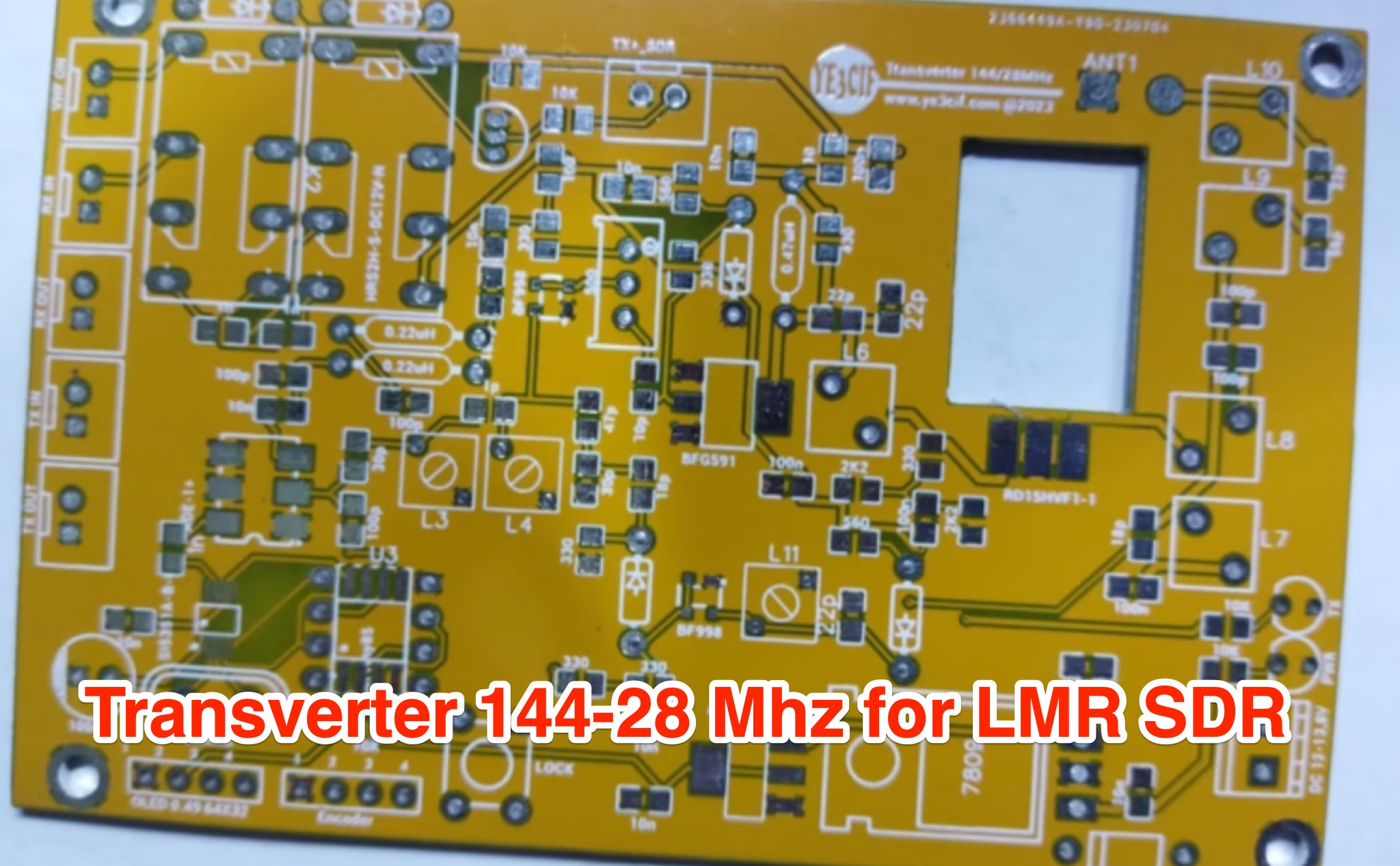 Learn how to build a VHF 144MHz transverter connected to an LMR SDR radio using easily accessible components. The transverter works by mixing the 144Mhz input frequency with a 116 MHz local oscillator frequency. Explore the challenges of finding a 116 MHz crystal and the solution of using a programmable Si5351A oscillator. Follow the provided schematic for the RX and TX sections. The transverter design is still a work in progress, with ongoing trials to achieve optimal results.
 -
 Discover the secrets of Six Meters with this comprehensive eBook by Jim Wilson, K5ND. Learn about the magic of 6-meter DXing, including propagation, antennas, equipment, operating software, and more. Whether you're a beginner or an experienced ham radio operator, this book covers everything you need to know. With over 8,000 downloads, this updated version includes new chapters on FT8/FT4, MSK144, and Q65 modes, as well as contesting, rover operation, and awards. Get your hands on this valuable resource and enhance your 6-meter DXing experience today.
 -
 Effective suppression of harmonics and parasitic radiation from HF transmitters is crucial, especially with the increasing sensitivity of VHF/UHF radio channels to interference. This project details a hybrid low-pass filter (LPF) designed to operate across the HF bands up to 51 MHz, making it suitable for 6-meter band operations while providing deep VHF/UHF suppression. The design addresses the challenge of modern interference landscapes, where even microvolt-level signals can disrupt wireless sensors and other simple VHF/UHF receivers. The filter utilizes a single elliptic link, combining high cutoff steepness with robust suppression in the hundreds of megahertz range. A key feature is the use of only two standard capacitor values, simplifying construction and component sourcing. The article provides a detailed schematic, performance characteristics, and _RFSim99_ model file, demonstrating a reflection coefficient S11 below 0.017 (VSWR < 1.03) across 1-51 MHz, ensuring minimal degradation to the antenna system. Construction notes include coil winding specifications and capacitor selection guidance, with recommendations for _FR-4_ assembly. Two capacitor sets are presented, with the first variant recommended for its lower RF current demands, keeping currents below 3 A at 1 kW passing power at 51 MHz. Fine-tuning involves adjusting frameless coils, with considerations for capacitor tolerance and high-frequency capacitance measurement accuracy.
 -
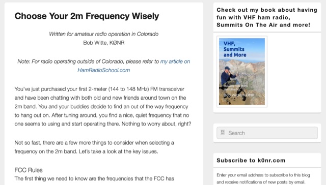 When new to the 2-meter FM transceiver, securing a quiet frequency for chatter seems straightforward, but it's essential to navigate FCC rules and band plans effectively. Even though frequency allocations are consistent above 50 MHz for Technician licenses, adherence to specific segments within the 2m band—ranging from 144 MHz to 148 MHz—is crucial. This includes respecting designations for different modes like CW, SSB, and FM to prevent interference, particularly with satellites and exotic modes like EME. Understanding and following the structured band plans not only ensures legal compliance but also optimizes frequency use and minimizes disruptions in the amateur radio community.
 -
 An FT-817 ceased transmission on the VHF 2m band, despite the other HF, UHF, and 50 MHz bands operating correctly. Suspecting an excess of input signal during FT-8 mode transmission, they conducted measurements with an oscilloscope, revealing a burnt-out PIN diode, identified as D3003, type HSU277, on the PA unit board. Following the replacement of this surface-mounted diode, their FT-817 resumed operation on the 144 MHz band.
 -
 This resource provides an in-depth look at Earth-Moon-Earth (EME) operating techniques specifically for the 432 MHz band and above. It outlines the differences in operational procedures between the 144 MHz and 432 MHz bands, emphasizing the importance of sequence lengths and scheduling. The initial calling period typically starts on the hour, with the eastern-most station calling first, which is crucial for effective communication. The document also discusses the challenges faced by operators, such as signal readability and the necessity of confirming exchanges. It highlights the significance of using a standardized procedure to enhance the likelihood of successful contacts. Additionally, it covers the use of signal reports and the importance of patience and clarity in communication, especially when dealing with weak signals. Overall, this guide serves as a valuable resource for amateur radio operators interested in improving their EME operations.
 -
 This paper by Leif Asbrink (SM 5 BSZ) presents a practical approach to designing very high gain Yagi antennas, focusing on the "brute force" optimization method. The method, described in a previous article, ensures convergence independent of initial guesses. The paper provides detailed tables of element lengths and positions for Yagi antennas optimized for 144.1 MHz with a 50-ohm feed point impedance, aiming for minimal losses and high accuracy in comparisons.
 -
 The article discusses the construction of a UHF band-stop stub filter to protect an APRS receiver from potential damage during a balloon launch. The author, who communicates using a 441 MHz transmitter, needed to ensure that the RTL-SDR dongle receiving at 144 MHz wouldn't be damaged by the transmissions. The solution involved creating a quarter-wavelength open stub filter using coaxial cable, which attenuates the 441 MHz signal while allowing the 144 MHz signal to pass through. The filter's design is based on the principles of constructive and destructive interference, with careful measurement and trimming to achieve the desired frequency response. The final filter provided 34.8 dB of insertion loss at 441 MHz and minimal loss at 144 MHz, effectively protecting the receiver.
 -
 The project aims to create a remote control system for the VK5RSE beacons located near Millicent, South Australia. The beacons on 144.550, 432.550, and 1296.550 MHz can interfere with nearby amateur radio operations, particularly for EME work on 1296 MHz. The remote control system uses a DTMF decoder and PIC microcontroller to allow turning the beacons on and off individually or in combination. The system is housed in a diecast box and powered from 5-8V. The password-protected control allows authorized users to manage the beacon operations remotely, helping mitigate interference issues for local amateurs.
 -
 Details the Virtual COM Port (VCP) drivers for Silicon Labs CP210x USB to UART Bridge devices, which are crucial for establishing serial communication between a host system and CP210x-based hardware. It covers driver availability for Windows, macOS, Linux, and Android, highlighting the necessity of these drivers for operating CP210x products as a virtual COM port. The resource also mentions the option for direct access drivers and references _Application Note 197_ for comprehensive serial communication guidance. The page specifies that the CP210x Manufacturing DLL and Runtime DLL have been updated, requiring their use with v6.0 and later of the Windows VCP Driver, impacting specific application note software downloads like AN144SW.zip. It notes that Linux 3.x.x and 4.x.x driver versions are maintained within the _Linux kernel tree_ at www.kernel.org, ensuring ongoing support. Legacy OS software is also provided for users requiring support for 5.x drivers, ensuring broad compatibility.