Search results
Query: 7 MHz band
Links: 530 | Categories: 11
Categories
- Operating Modes > 70 MHz
- DX Resources > Beacons > 10 meter beacons
- Antennas > 20M
- Antennas > 23cm
- Antennas > 2M
- Antennas > 30M
- Antennas > 40M > 40 meter Dipole Antennas
- Antennas > 40M > 40 meter Yagi Antennas
- Antennas > 4M
- Antennas > 6M > 6 meter Moxon Antennas
- Radio Equipment > HF Vertical Antenna > Maldol MFB-300
-
 A QRP transceiver for 80 meters band by W1FB
 -
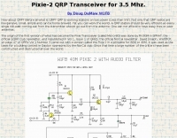
 7N3WVM homebrew project of a 3 W output CW transceiver on 7 MHz band
 -
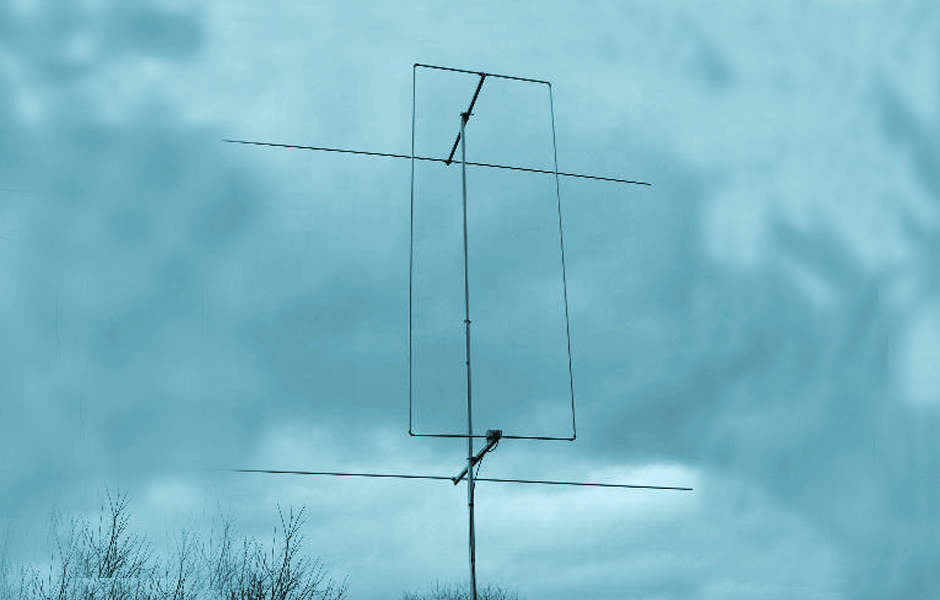 The Quadlong antenna for the six meter band. This antenna feature a total gain of 6,4 dBd, F/B 21 dB and is also available in 70MHz version. Includes detailed pictures and plot diagrams.
 -
-
 A 21 MHz Four Square Beam Antenna This popular antenna for the lower bands, can also work well on 15 meters, QST Article
 -
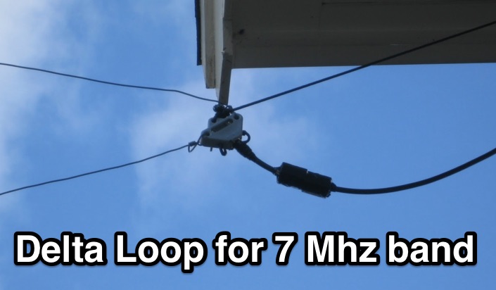 Antenna experiment a Delta loop antenna for 7 Mhz band
 -
 A SSB CW transceiver for six meters band with schematic and block diagram
 -
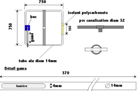
 A moxon rectangle for 50 Mhz band
 -
 The YB7ZGP Pamaton Repeater operates on a frequency of 146.76 MHz, serving the Martapura District in Banjar, South Kalimantan, Indonesia. This VHF repeater provides local communication infrastructure for amateur radio operators in the region. The repeater's operation is managed by Syah Riyan, indicating a local amateur radio enthusiast or group maintains the station. Repeaters like YB7ZGP are critical for extending the range of VHF/UHF communications, allowing handheld and mobile transceivers to communicate over greater distances than line-of-sight. The 146.76 MHz frequency falls within the 2-meter band, a popular segment for local and regional amateur radio traffic, often utilized for emergency communications and general ragchewing. Information regarding the _Pamaton Repeater_ is presented on a blog platform, suggesting a community-driven effort to disseminate details about this local amateur radio asset.
 -
 An inverted triangle Delta Loop Antenna for the 40 meter band made with aluminium pipes, each element is 14,2 meters including a home made aluminium mount.
 -
 Establishing a robust, interconnected communication infrastructure across challenging terrain, the Island Trunk System (ITS) provides a network of open amateur radio repeaters for general and emergency communications throughout Vancouver Island, surrounding waters, and parts of the lower mainland on the West Coast of British Columbia, Canada. This system, largely off-grid, relies on solar power and batteries, necessitating careful operation, especially during night hours and low solar charging seasons, to preserve its energy resources. Maintaining the ITS involves significant effort from many hams, who appreciate adherence to regulations, including proper station identification. The system hosts a weekly social net every Monday evening at 8 PM, welcoming all participants, and also supports a Vancouver Island Region Emergency Radio Net each Wednesday at 19:15. Experimental projects like the Newcastle Ridge webcams, linked via 5.8 GHz broadband backhaul over 206 km to Nanaimo and Comox, demonstrate the innovative spirit within the ITS community. A new VHF repeater, operating on 146.880 MHz with a 141.3 Hz PL tone, was installed in Tofino, expanding system coverage.
 -
 A vertical antenna for 40 meters band by PA5MW
 -
 The NCDXF/IARU International Beacon Project operates a worldwide network of 18 high-frequency radio beacons, continuously transmitting on 14.100, 18.110, 21.150, 24.930, and 28.200 MHz. These beacons, initially launched in 1979 with a single station and expanded to the current 18-beacon system in 1995, provide reliable signals for both amateur and commercial users to assess current **ionospheric propagation** conditions. The system's design, construction, and operation are managed by volunteers, covering hardware and shipping costs. The resource details the evolution of the beacon network, including the transition from Kenwood TS-50s transmitters to Icom IC-7200 radios with a new controller design implemented in 2015. It explains how listening for these 100-watt signals, transmitted to vertical antennas, allows operators to determine band openings and optimal propagation paths globally. The content also references three QST articles providing historical context and technical specifics of the beacon project. Practical information includes methods for identifying transmitting beacons via a schedule or specialized software like FAROS and Skimmer, which integrates with the **Reverse Beacon Network** for automated monitoring.
 -
 A Loop Fed Array Yagi antenna for 50 MHz featuring 11 dBi gain and 23 f/b ratio. In this excellent page the author even includes a detailed drawing in DWG format, with element lenght and spacing measures, in a separa file a full list of material list needed to build this yagi antenna including source and price, the EZnec file for this antenna plan, and a lot of pictures of this LFA Yagi for 50 Mhz. A ten page PDF file containing all infos, is also available to download.
 -
 Demonstrates the construction of a 144 MHz turnstile antenna, detailing its design for omnidirectional, horizontally polarized VHF operation. The resource outlines the physical dimensions and materials required, including specific lengths for the radiating elements and the use of _RG-58_ coaxial cable for phasing. It covers the assembly process, emphasizing the critical spacing and connection points to achieve the desired radiation pattern and impedance matching for the _2-meter band_. The article presents measured _SWR_ performance across the 144-146 MHz segment, showing a low SWR of 1.2:1 at 144.5 MHz, which is suitable for general VHF use. It compares the turnstile's performance to a 9-element Yagi, noting the turnstile's advantage in providing consistent signal strength from all directions without requiring a rotator. Practical application for local FM simplex and repeater operations is implied, offering a simple yet effective antenna solution for fixed or portable stations.
 -
-
 One point eight MHz to 30 MHz is the operational bandwidth for this 4:1 Ruthroff voltage balun, designed to interface an unbalanced T-Match network with a balanced antenna system. The project details the construction using a _T200-2_ powdered iron toroid core, tightly wrapped in PVC electrical tape for insulation, and wound with 17 double bifilar turns of 1.25mm enamelled copper wire. This outboard balun offers flexibility, allowing hams to trial various baluns based on antenna system and impedance characteristics, rather than integrating it directly into the tuner. The resource includes a schematic of the balun, a wiring diagram showing winding connections, and a table suggesting alternative toroid cores like the T80-2 or T400-2 with corresponding winding counts. Component sourcing is straightforward, listing items such as the _Amidon_ T-200-2 core, SO-239 connector, and a sealed polycarbonate enclosure from Jaycar. Performance evaluation was conducted using an _AIM 4170C_ antenna analyser, demonstrating efficient 1:4 voltage transformation across the specified HF spectrum. Further efficiency tests involved measuring RF power loss at various frequencies, revealing minimal loss—less than 0.7 dB from 3.6 MHz to 30 MHz, and only 2.0 dB at 1.8 MHz. These measurements, performed under ideal 50-ohm conditions, confirm the balun's effectiveness as a low-loss interface for multi-band antenna systems. The page also links to several other balun and unun projects, including 1:1 current and voltage baluns, and 9:1 voltage ununs, providing a broader context for impedance matching solutions.
 -
 Optimizing the ZS6BKW antenna for full HF band coverage often requires specific modifications beyond its standard configuration. This resource details several enhancements, beginning with a simple series capacitor to improve 80m SWR, a technique W5DXP found effective for permanent installation due to its minimal impact on higher bands. Further improvements include a 10-inch parallel open stub for 10m resonance, shifting the frequency to 28.4 MHz with an SWR of approximately 1.8:1, a practical solution for Technician class operators. The document then explores a switchable matching section, adding or subtracting one foot of ladder line at the 1:1 choke-balun, which significantly impacts higher frequency bands and eliminates the need for a tuner on 17m. W5DXP's _AIM-4170D_ antenna analyzer measurements confirm these effects. More advanced modifications involve a parallel capacitor for further 80m SWR reduction, requiring remote switching for multi-band operation, and relay-switched parallel capacitors at specific points on the 450-ohm matching section to achieve low SWR on 60m, 30m, and 15m. These detailed steps, including _Smith chart_ analyses for the challenging bands, aim to transform the ZS6BKW into a truly all-HF-band antenna, reflecting W5DXP's practical experience in antenna tuning.
 -

-
 Presents a curated collection of newsletters dedicated to _Earth-Moon-Earth_ (EME) communications, primarily focusing on the 432 MHz band and higher microwave frequencies. The resource details various EME DX experiences and news contributions from operators like K2UYH (W6/PA0ZN), offering insights into successful moonbounce contacts and operational strategies. It serves as an archive of specialized content for those engaged in or interested in extreme weak-signal propagation via the moon. The newsletters provide practical information on achieving EME contacts, often including details on station setups, antenna arrays, and signal reports from challenging DX. For instance, operators might report achieving contacts over **750,000 km** round trip, demonstrating the feasibility of long-distance communication on UHF and microwave bands. The content differentiates itself by concentrating on the unique technical and operational aspects of EME, which contrasts significantly with terrestrial DXing, providing a specialized knowledge base for advanced amateur radio operators.
 -
 This antenna is designed to be mounted off the side of a tower. Works on 136-153 Mhz range but also on 70 cm band
 -
 The page provides a project for an helical dipole for the 40 meters band, resonating on 7 MHz, created by PY1ZFK based on a design by DL8VO. It includes detailed instructions on building the antenna.
 -
 Presents a QRP AM/CW transmitter project specifically designed for the 10-meter band, utilizing a crystal oscillator and a collector-modulated AM oscillator. The design employs a 2N2219(A) transistor in a Colpitts configuration, generating 100 to 350 mW of RF output power depending on the 9-18 Volt supply voltage and modulation depth. Frequency stability is maintained by a 28 MHz crystal, with fine-tuning possible via a Ct1 trimmer capacitor for approximately 1 kHz adjustment. The resource details the RF oscillator stage, implemented with a 2N2219 NPN transistor, emphasizing frequency stability and low power dissipation. It also covers the amplitude modulation stage, managed by a 2N2905 PNP transistor, which impresses audio information onto the carrier. Selective components (C3, C4, C7, C5) enhance voice frequencies within a +/- 5 kHz bandwidth, and modulation depth is controlled by R2 and R3. The project includes a 3-element L-type narrow bandpass filter (Ct3, L3, C10) to suppress harmonics and ensure a clean output signal. The project provides a complete schematic diagram, a comprehensive parts list including specific capacitor, resistor, and inductor values, and construction notes for the coils (L1, L2, L3). It also offers practical advice on enclosure requirements, suggesting an all-metal case or a PVC box with graphite paint for RF shielding. Operational parameters such as current draw (27mA@9V to 45mA@16V) and input impedance (50 Ohms) are specified, alongside guidance on antenna matching and the importance of a valid amateur radio license for 10-meter band operation.
 -
 An optimized QRP transceiver for 40 meters band
 -
 The antenna is a VHF side is a 2m moxon, tuned on 145.825 MHz. The driven element of the moxon couples to a driven element for a 5 element 70cms Yagi, tuned on 436.5 MHz.
 -
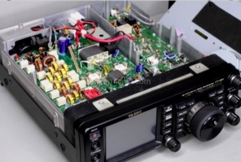 This modification will expand the tx frequency range of the Yaesu FT-991 from allowing just ham radio bands, to all bands 1.8 - 30MHz and 50-54 MHz.This information is solely for use by licensed members of MARS (Military Affiliate Radio System) or CAP (Civil Air Patrol)
 -
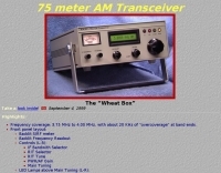 Frequency coverage: 3.75 MHz to 4.00 MH transceiver for 75 MHz band
 -
 The _Italian VHF Beacons_ resource provides a detailed listing of active and QRT amateur radio beacons operating across VHF, UHF, and SHF bands within Italy. Each entry specifies the beacon's callsign (e.g., IQ1SP/B), operating frequency (e.g., 144.411 MHz), QTH locator (e.g., JN44VC), effective radiated power (ERP) in watts, and antenna configuration (e.g., Big Wheel, 4x Dipole, Yagi). This data is crucial for radio amateurs involved in propagation studies, equipment testing, and long-distance (DX) communication on these higher frequency bands, offering fixed signal sources for monitoring. This compilation, last updated in October 2005, serves as a historical snapshot of Italian beacon activity. For instance, it lists several 144 MHz beacons with ERPs ranging from **0.1W** to **10W**, and higher frequency beacons such as I8EMG/B on 1296.880 MHz and I3EME/B on 24192.132 MHz. The inclusion of QRT (Quiet Radio Teletype) status for many entries indicates the dynamic nature of beacon operations over time. Users can utilize this information to identify potential signal sources for band openings or to calibrate their receiving equipment against known transmissions.
 -
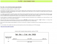 The original project of a dual band yagi antenna for 50 and 70 mhz, published on dubus 2/2007 by YU7EF
 -
 The webpage provides guidance on working 6 Meter DX, focusing on effective operating habits, preparation, and knowledge of the band. It emphasizes the importance of monitoring, clear frequencies, and using CW for weak signals. It also mentions the significance of knowing countries and individual stations on the air to increase chances of working DX. The page recommends utilizing resources like newsletters and websites to stay updated on 6-meter activity and offers suggestions for improving operating skills.
 -
-
 This Z-Match is a link coupled all-band tuner. Two all band tank circuits cover 3-14mhz and 14-30mhz. The tank output links are selected with a very heavy duty SPDT rotary switch.
 -
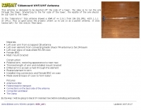
 A project of a small antenna, just 50 cm for the 7 MHz band. An EH Antenna plan for the 40 meters band
 -
 This project details the construction of a **full-sized 40-meter vertical antenna**, born from a renewed interest in 7 MHz operation and a desire for improved effectiveness over simple dipoles. The author, K5DKZ, initially focused on VHF experimentation, which provided an inventory of aluminum tubing and fiberglass spreaders for this endeavor. Before this vertical, K5DKZ utilized an 80/40 meter inverted-vee trap dipole and a 40-meter broadband dipole, but now primarily uses a pair of full-sized, phased, quarter-wave verticals spaced 35 feet apart for serious 40-meter work. The construction involves a base-heavy design for stability, using a 44.5-inch section of 1-1/4 inch steel TV mast driven into 1-3/8 inch aluminum tubing, insulated by a 105-inch section of Schedule 40 PVC pipe. The assembly reaches 31 feet, close to the 32 feet required for a quarter-wavelength on 40 meters, with fine-tuning achieved by winding wire onto a fiberglass spreader. The design is explicitly presented as a foundation for a two-element 40-meter Yagi beam, outlining modifications like substituting aluminum for steel in the base and using an inductive hairpin match for the driven element. The article also discusses tuning considerations for a large 40-meter beam, noting the 100 to 200 kHz upward frequency shift when raised, and suggesting methods for installation on a tower. The author emphasizes the cost-effectiveness and good performance of the monopole approach, especially when multiple verticals are needed.
 -
 The Yaesu VX-5R, manufactured between 199x and 200x, offers a transmit frequency range covering 50-52 MHz, 144-146 MHz, and 430-440 MHz for European models, with US versions extending to 50-54 MHz, 144-148 MHz, and 430-450 MHz. Its receiver boasts an impressive wideband capability from 0.5 MHz to 999 MHz, with cellular frequencies blocked in some regions. The unit provides up to 5 watts RF output on 6 meters and 2 meters, and 4.5 watts on 70 centimeters, with selectable lower power settings down to 300 mW. This handheld transceiver utilizes a double conversion superheterodyne receiver system, featuring a 47.25 MHz first IF for FM and 45.8 MHz for WFM. Key specifications include a frequency stability of ±5 ppm across a wide temperature range and a current drain of 25-150 mA on receive. The VX-5R supports 220 regular memory channels with alpha tags, 3 home channels, and 10 NOAA weather channels, all stored in non-volatile EEPROM. Additional features include CTCSS/PL and DCS with tone search, ARS, ARTS, an internal voltmeter, and a Spectra-Scope. The device operates on a 7.2 VDC battery pack or 10-16 VDC external power, weighing 255 grams with dimensions of 58x88x27 mm. The VX-5R was also available as the metallic silver VX-5RS.
 -
 This document details the design and construction of the PA70H, a 50-watt RF amplifier for the 70MHz (4-meter) amateur radio band. Built around the Mitsubishi RD70HVF1 MOSFET transistor, the amplifier delivers 45-55W output with 3-5W input power while operating on 13.8V DC at approximately 7-8A. The PCB design incorporates multiple protection circuits including overcurrent, SWR, and temperature control. The amplifier features various control modes including GND PTT, +13.8V PTT, and RF VOX. Two versions are available: PA70HLI (requiring 100mW input with additional driver) and PA70H (for 3-5W input). The comprehensive documentation includes circuit diagrams, assembly instructions, and performance data showing successful operation from both 100mW and 3.5W input sources.
 -
 One of just a few webpages for the magic band, see it from the german point of view.
 -
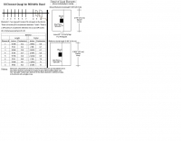
 Fill out the form to design a bandpass filter as described in the January 1985 issue of Ham Radio Magazine. These filters are generally limited to frequencies above 200 MHZ because their size is slightly longer than 1/4 wavelength
 -
 A 5 elements homemade DK7ZB yagi antenna for 4 meters band based on a 50MHz TONNA
 -
 Demonstrates the adaptation and construction of a 7-element DK7ZB Yagi antenna for the 4-meter band (70 MHz), utilizing components from a defunct 2-meter CUE DEE Yagi. The resource details the modifications made to the original DK7ZB design to fit the shorter CUE DEE boom length, specifically adjusting element lengths for 6mm rod elements while reusing existing mounting holes for the reflector and last director. It provides precise element lengths for the reflector, dipole (12mm aluminum tube), and five directors, along with a note on cutting elements for transport. The article includes a 4NEC2 simulation file for performance analysis and an SWR plot, confirming the antenna's electrical characteristics. It also specifies the calculation for the quarter-wavelength matching cable using SAT752F coaxial cable, resulting in a 909mm length. Practical application is shown with the finished antenna in operation at JO20XC, listing several activated Maidenhead squares such as JO56PA and JP40KS, validating its effectiveness for portable 70 MHz operations.
 -
 5-element antenna, with which G0JJL has worked lots of EU crossband, and won the RSGB Christmas Cumulatives 70MHz section twice in a row.
 -
-
-
 This is a prototype of the WA4DSY 56KB RF modem. It is intended for use on amateur packet radio networks. The modem generates RF in the 28 to 30 mhz range and requires and linear transverter to convert the signal to a UHF or microwave ham band
 -
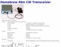
 A simple fixed frequency SSB voice transceiver for the 7 MHz amateur band
 -
-
 The 10-minute, 25-second video demonstrates making a QSO via the VO-52 amateur radio satellite, focusing on real-time Doppler shift correction. It features Simon, 2E0HTS, operating a Yaesu FT-847 transceiver and a homebrew dual-band Yagi antenna, specifically a 10-element 435 MHz Yagi for uplink and an IO Loop for 145 MHz downlink. The video visually details the operator's technique for continuously adjusting the uplink frequency to compensate for the satellite's changing velocity relative to the ground station, a critical aspect of successful satellite communication. The demonstration highlights the practical application of Doppler compensation, showing the operator tuning the transmit frequency to maintain a stable received signal from the satellite. This approach contrasts with systems employing automatic Doppler correction or full-duplex operation, providing insight into manual frequency management for satellite passes. The video serves as a direct, observational guide for hams interested in LEO satellite operations, particularly those using non-tracking, manually tuned setups.
 -
 EF0603S is a 3 element portable yagi antenna for six meters band by YU7EF
 -
 In this PDF article Zack Lau describe how to homebrew a four element yagi beam antenna for 50 MHz band, including how to build mounting blocks and tubing clamps to hold elements.
 -
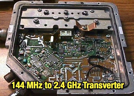 A home made project, scan and monitor the 2.4 GHz band using a common MMDS downconverter.