Search results
Query: 50 Mhz
Links: 403 | Categories: 8
Categories
- Operating Modes > 50 MHz
- Antennas > 6M > 6 meter Moxon Antennas
- DX Resources > Beacons > 6 meters beacons
- Antennas > 6M
- Radio Equipment > HF Transceivers > Icom IC-703
- Radio Equipment > HF Transceivers > Icom IC-7610
- Radio Equipment > HF Transceivers > Icom IC-7760
- Manufacturers > Antennas > VHF UHF Microwave > Microwave antennas
-
 The Boone Area Radio Klub (BARK) serves Boone County, Iowa, as its local amateur radio club, actively welcoming visitors to its meetings and weekly ARES nets. The club maintains a 2-meter repeater on 146.850/250 MHz with a 114.8 Hz tone and a 440 MHz repeater on 443.9+ MHz, both situated at the Boone County Hospital, with a simplex fallback on 146.550 MHz for the 2-meter net. Additionally, BARK supports the Iowa 160-meter ARES net at 1.972.5 MHz, which operates at 9:30 PM on Sundays, featuring a rotating schedule of net controls including KNØR, KBØMPL, NØISU, KEØQEU, and KBØLPI. BARK conducts bimonthly license testing sessions on the second Saturday of even-numbered months, with specific dates like October 19, 2024, at the Hamboree, requiring a $15 fee and prior FCC Registration Number (FRN) acquisition. The club's activities are well-documented through numerous photo galleries from past Field Days (1998, 1999, 2008, 2010, 2013, 2017, 2018, 2019), JOTA events (2013), and special event stations (2010 B&SVRR&M). Members like KBØMPL (Margot Conard) have contributed educational PowerPoint presentations on topics such as "Fun with Handie Talkies," "HF Propagation," and "Digital Mode - FLDIGI - OLIVIA 8/500 - JT65 HF - BAND PLANS." The club's officers, as of May 2018, include WØFS (Clay Conard) as President, NØISU (Mitch Carroll) as Vice-President, and KBØLPI (Eric Sloan) as Treasurer/Secretary, guiding the club's operations and community engagement.
 -
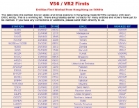
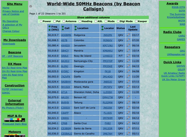 World-Wide 50MHz Beacons database maintanied by G0LGS provide a fully sortable table available also in a google map format
 -
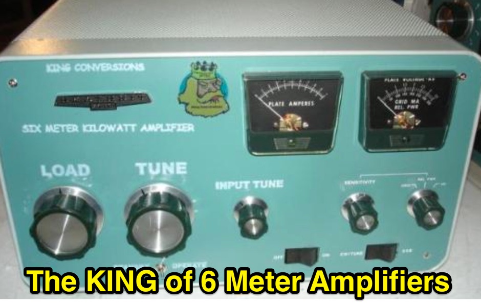 King Conversions has extensive experience in amplifier repair and conversion King Conversions specialize in converting HF amplifiers to operate as monoband amps on 50 MHz
 -
 Helix antenna 432/435 MHz 14 turns. This 50 ohm impedance antenna allows, when fed with 25/50W of SSB RF, to join the orbiting satellites like AO-40 and AO-10 very easily
 -
 The page provides information on a simple 50MHz J-Pole Antenna project based on the DK7ZB design. It explains the principle of the Wireman-J-Pole, the feeding process, practical mounting, and simulation results using MMANA GAL. The content aims to guide amateur radio operators in building their own J-Pole antennas for the 6-meter band.
 -
 Over 150 pages of content are dedicated to maximizing activity on the 6-meter band, often referred to as the _Magic Band_. The resource details various propagation modes, including sporadic E, F2, and tropospheric ducting, providing insights into their characteristics and how to leverage them for DX contacts. It also covers essential equipment considerations, from transceivers and transverters to specific antenna designs optimized for 50 MHz operation, such as Yagis and Moxon antennas. The eBook presents strategies for participating in 6-meter contests and pursuing awards like _VUCC_, offering practical advice on logging software and operating techniques. It includes discussions on software tools useful for predicting propagation and managing contacts, alongside guidance on finding and utilizing DX maps to identify openings. The author, K5ND, shares his extensive experience to help operators achieve successful 6-meter DXing. Specific sections address the code of practice for 50 MHz operations and provide assistance in locating rare DX opportunities. The content is structured to guide both new and experienced operators through the nuances of the band, from initial setup to advanced operating strategies.
 -
 Laboratory 599 makers of the DISCOVERY HF/50 MHz SDR Ultra-compact Trasceiver.
 -
 The CQ Contest & DX Group, main activities is - participating in contests. Mainly in the Nordic Activity Contest at the 50 MHz, 144 MHz and 432 MHz, though the group holds a full licence, have we not participated in a HF contest yet.
 -
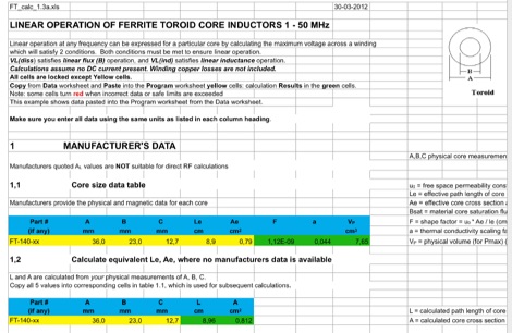 This EXCEL Program Worksheet calculates the safe operating conditons for a toroidal transformer operating between 1 and 50 MHz. Manufacturer data for complex permeability, magnetic dimensions, and saturation flux density must be available. Some core types which are commonly used in amateur transmission are included. The program produces limiting winding voltages for linear operation and temperature rise over the range of frequencies and power specified.
 -
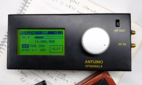 Antuino is an accurate instrument that can be used in the field to measure SWR, field strength, modulation, etc. In the lab, it can be used to sweep filters, measure gain, distortion, frequency response, etc. It works upto 150 Mhz. On the third harmonic, it is usable on 435 Mhz band as well (with reduced sensitivity).
 -
 The Baofeng UV-5R handheld transceiver, introduced around 2012, operates across the 2-meter (144-148 MHz) and 70-centimeter (420-450 MHz) amateur bands, offering dual-band receive and transmit capabilities. This review provides an early assessment of the radio's form factor, user interface, and general performance, noting its compact size and the inclusion of a **VFO/Memory mode** button for frequency management. The device supports both FM and narrow FM modes, with a reported power output of 4 watts on VHF and 3 watts on UHF, making it suitable for local simplex and repeater operations. Key features discussed include its 128-channel memory capacity, a built-in VOX function, and a **DTMF keypad** for tone dialing and repeater access. The review highlights the radio's ability to scan frequencies and memories, along with a dual-watch function allowing simultaneous monitoring of two frequencies. Battery life is addressed, with the standard 1800 mAh Li-ion pack providing several hours of operation depending on transmit usage. Initial impressions cover the radio's construction and the clarity of its LCD display, which shows both A and B band frequencies.
 -
 A homemade delta loop antenna for six meters band in German
 -
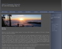
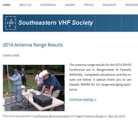 A not-for-profit organization incorporated to promote ham radio operation on the bands above 50 MHz in the southeastern United States.
 -
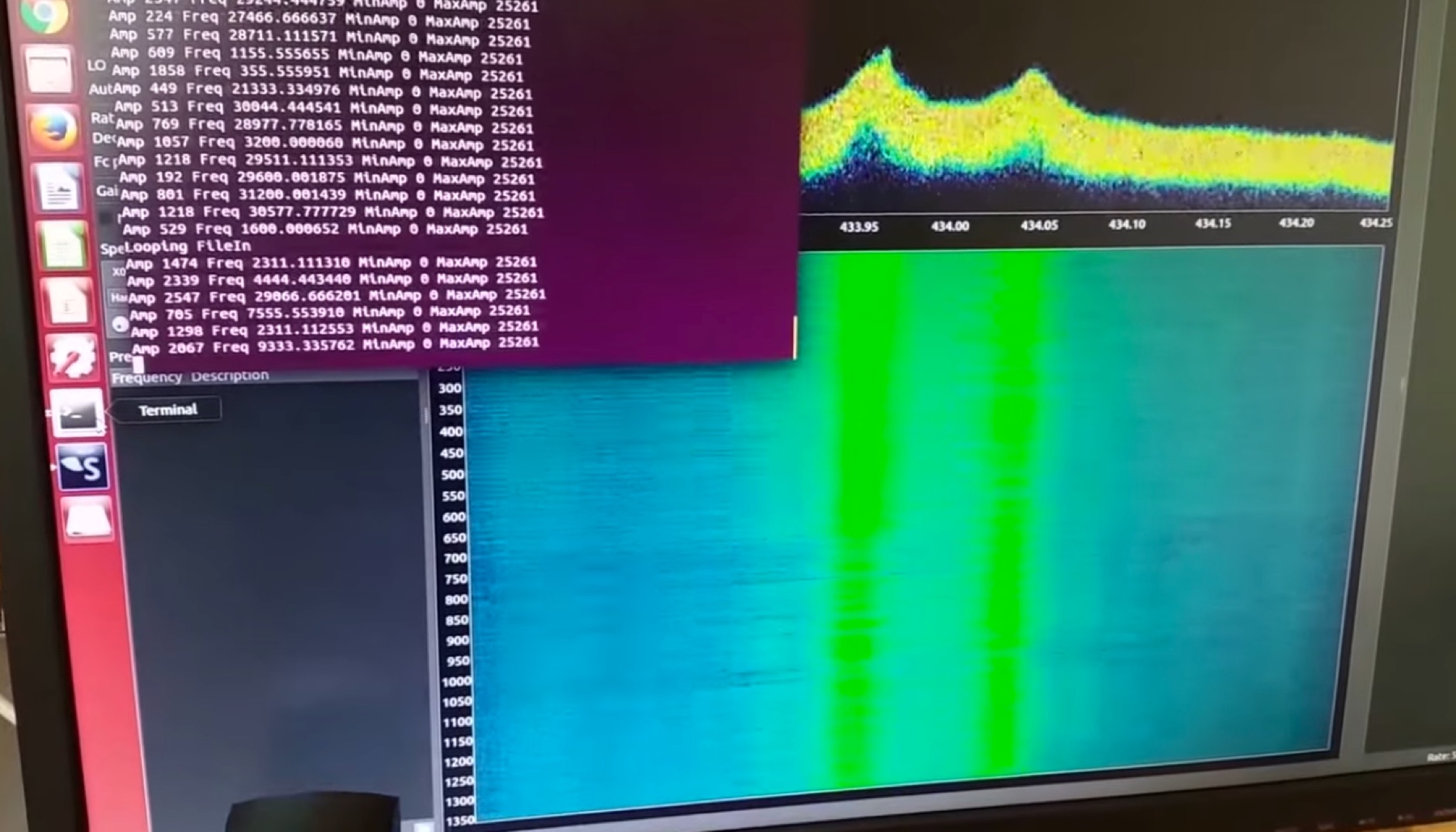 rpitx is a general radio frequency transmitter for Raspberry Pi which doesn't require any other hardware unless filter to avoid intererence. It can handle frequencies from 5 KHz up to 1500 MHz.
 -
 A small antenna for 50 MHz made with copper cable loading coils
 -
 The J Pole antenna is a good omnidirectional antenna that can be used for portable or fixed station usage. It does not need a ground, and neither complex feed systems. It can be homemade with simple material and in several ways.Article in Italian
 -
 Stacking yagi antennas for 50 Mhz band article by by Zaba, OH1ZAA/NN0Y
 -
 This antenna is a classical antenna working on 7,10,14,18,50 MHz is implemented with three traps for 30, 17 and 6 meters
 -
 An Hentenna project for the six meters band. The standard size of standard hentenna is width 1/6 wavelength x height 1/2. The antenna build in this project is a full wavelenght antenna for the 50 MHz providing a 6.8 dbi gain.
 -
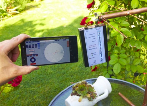 Antenna Analyzer plus 500 is a multifunctional measuring instrument, very useful for amateur radio activity. Its size allows you to easily take it for relocation as well. Frequency range: 100KHz - 500MHz. Access directly via WiFi. Includes a dual-channel signal generator
 -
 W7GJ 50 MHz EME DXpedition July 12 - July 28, 2014
 -
-
 A collection of 450 MHz Cheap Yagis that have proven great portable operations, back-packing and transmitter hunts, and are something inexpensive you can throw up in the attic for that weak repeater
 -
-
 The Terminated End Fed Vee Antenna (TEFV) is a travelling wave antenna with constant current distribution. Unlike traditional resonant antennas, TEFV operates without standing waves, using a terminating resistor for broadband efficiency. With a combination of vertical and horizontal polarization, it offers wide bandwidth from 1.8 MHz to 30 MHz, eliminating the need for a tuner. Key components include a 9:1 unun transformer and a 500-ohm terminating resistor. Grounding and counterpoise enhance performance, and it can handle power losses of up to 30%. TEFV provides an effective, versatile antenna solution for amateur radio and broadcast applications.
 -
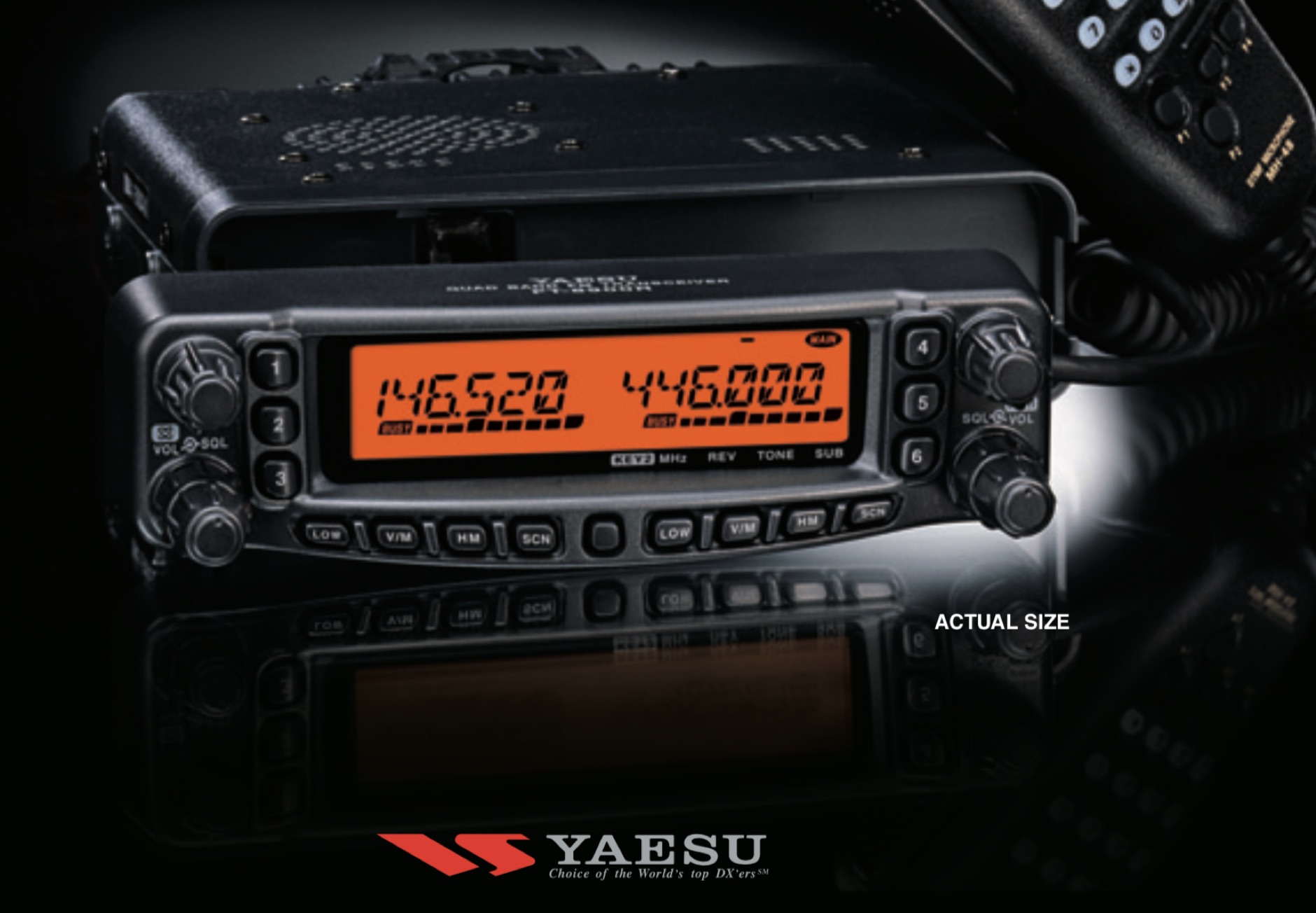 A review of the Yaesu FT-8900r 29/50/144/430 MHz FM Transceiver, providing 50 Watts of power output on the 29/50/144 MHz Amateur bands, and 35 Watts on the 430 MHz band.
 -
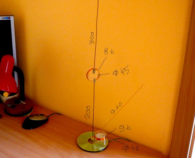
 This J-Pole is mounted on a fishing rod. The radiator L1 is an isolated copper-wire with a length of 281,5 cm while the quarter-wave matching sector L2 is made with 450-Ohm-Wireman-cable
 -
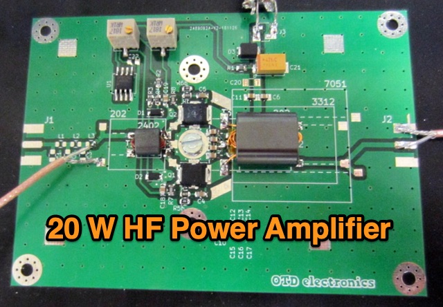 A HF power amplifier with a push-pull of AFT09MS015N. The (small-signal) gain of the amplifier is around 26 dB in the lower HF band and goes down to about 24 dB on the higher end and still around 21 dB at 50 MHz. Its input matching is relatively good at the lower HF and degrades above 10 MHz.
 -
 Enables Android users to operate various _miniVNA_ antenna analyzers via Bluetooth, USB, or Wi-Fi, providing a portable solution for RF measurements. The application supports full control over data acquisition, offering features like custom frequency range selection from 1 KHz to the VNA's full range, and automatic screen adaptation for diverse Android device resolutions. It facilitates intuitive, wizard-based calibration for both reflection and transmission modes, saving calibration data for different VNA types (Standard, Pro, Pro with Extender) to avoid repeated procedures. The software displays critical parameters such as SWR, |Z|, Return Loss, Phase, Rs, and |Xs| on 2-axis graphs or Smith charts, with multi-touch gestures for zoom and frequency shift. It includes a frequency generator mode with independent channels and attenuator control for the miniVNA Pro, along with a sweeper function. The cable data mode automatically calculates phase and loss, measures cable length from less than 1 meter to hundreds of meters, and includes a table of common coax cable velocity factors. An experimental X-tal mode measures resonance frequency, Rs, and Q. Data export options include CSV, ZPLOT, and S1P formats, with CSV import capability. The application also features an SM6ENG Audio mode for SWR tuning without visual reference and provides a miniVNA battery voltage indicator. It supports a wide frequency range, with the miniVNA Extender extending coverage up to **1500 MHz**. The application is compatible with Android version 2.2 and later, tested on devices like the _Galaxy TAB 7.7 P6800_.
 -
 I used a FT 240-43 for much more power, not needed but beter safe than sorry. 150 Watt continious, 300 Watt PEP SSB, 90 Watt Digimodes 10 Mhz, 18 Mhz, 24 Mhz Very easy to build design and a good antenna for people who don't have much space for big towers or long wires This design is from Hans - PE1RNU
 -
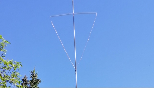
 Building A Full-Wave Quad Loop Antenna for 6 Meters. This is an easy antenna to build and the materials cost about $15-20. It exhibits 1.8dB gain over a 1/2-wave dipole. Using an open-wire parallel feedline (commonly called ladder line) with an antenna tuner, it tunes up on the 10m band as a 5/8-wave loop as well
 -
 Home of GB3FH, 50.770MHz CTCSS 77.0Hz
 -
 The Covey Hill Amateur Radio Club operates a 146.685 MHz analog repeater with an 88.5 Hz PL tone, alongside several digital repeaters. The resource details specific frequencies and modes for D-STAR (145.590 MHz, 1266.300 MHz voice, 1297.675 MHz data on 23 cm), DMR-Marc (448.525 MHz), DMR-Brandmeister (441.750 MHz), Yaesu Fusion (449.725 MHz), and P-25 Digital (147.315 MHz). It also lists Echolink node 595040 (VE2REX-R) as an access point for the club's network. A recent update, dated June 19, 2024, announces the VE2REX analog repeater and Echolink are fully functional again, after resolving issues including a conflicting 100.0 Hz tone, software repairs for Allstar and Echolink, a suspected defective USB port on the Mini PC, and a faulty exciter in the Motorola Quantar repeater. Guy, VE2VMT, was instrumental in troubleshooting these problems. The club, established in 1994, provides a calendar, news, links, and membership information, with Linda Cullen, VE2NJK, serving as president and VA2DBJ as webmaster.
 -
 Sporadic E is a form of propagation that can arise with little warning, and enable radio frequencies of 150 MHz and more to travel over distances of a thousand kilometres and more.
 -
 Presents Wayne Kerr Electronics, a manufacturer specializing in precision component measurement products. The company offers a range of LCR meters, impedance analyzers, and transformer test systems designed for various applications in electronics manufacturing and research. Specific product lines include the 3260B Precision Magnetics Analyzer, which measures inductance, capacitance, and resistance with high accuracy, and the 6500B series of LCR meters, capable of testing components across a broad frequency range up to 120 MHz. The 3255B and 3265B series provide solutions for transformer and inductor testing, including turns ratio, leakage inductance, and inter-winding capacitance measurements. These instruments are utilized in quality control, component characterization, and production line testing, ensuring performance and reliability in electronic circuits. Wayne Kerr's offerings support engineers and technicians in verifying component specifications.
 -
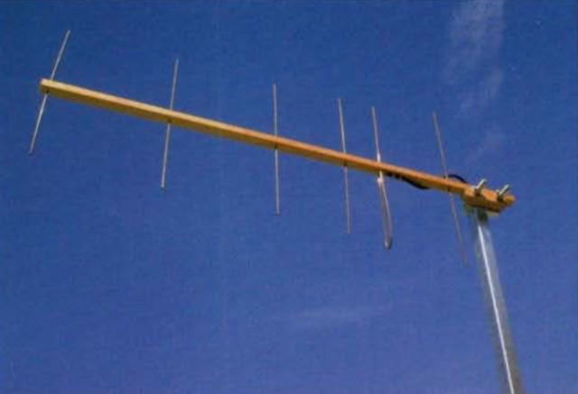
 Experimental Long Boom Antennas - CP, LPDA, multiband with several NEC Files for 50MHz 144MHz 222 MHz 432MHz but also 902MHz and 1296 MHz Antenna projects. Includes also for each antenna model, in a general comparison table each antenna characteristics including Directive Gain, G/T, E-F/R, H-F/R abd Boom Length. This is a great value comparison table of several commercial and home made VHF UHF antenna projects.
 -
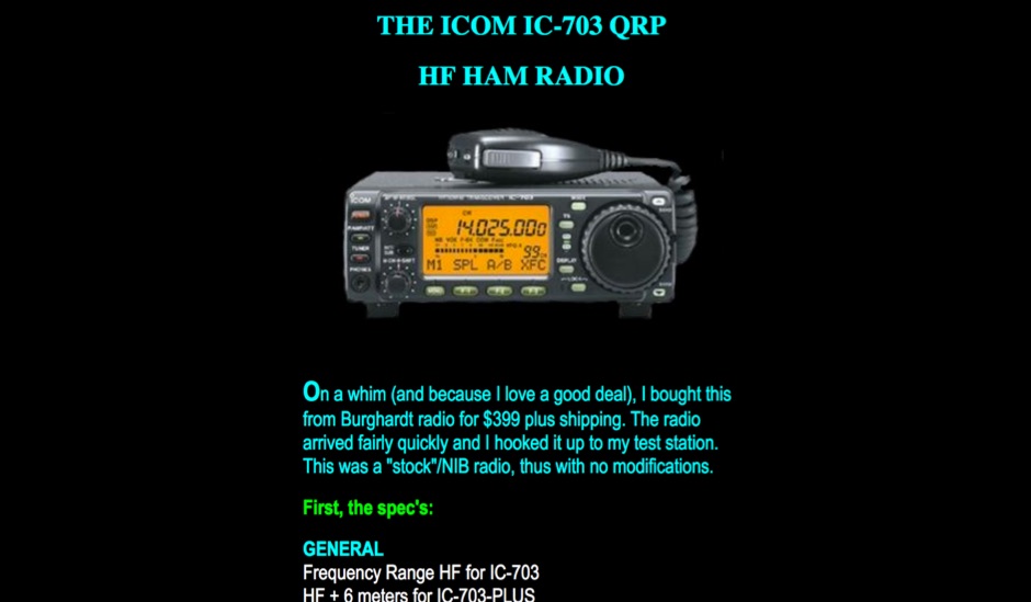 A review with early observations and technical data specifications of the Icom IC-703 QRP HF+50 MHz transceiver
 -
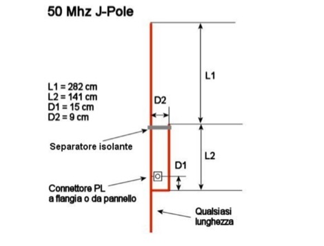
 A j-pole antenna plan with drawings and dimensions that can help you on building your own j-pole antenna for the six meters band
 -
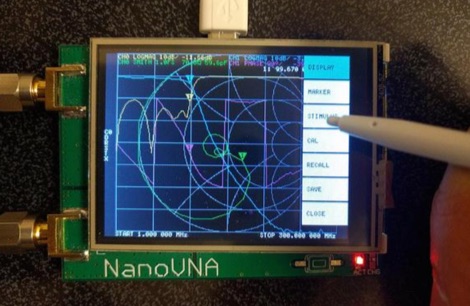 Very Tiny Palmtop Vector Network Analyzer by edy555. This is the original GitHub firmware repository implementing the standard 50KHz to 300MHz model
 -
 The ICOM IC-7610 SDR HF/50MHz Transceiver official product page with product specifications, option accessories and video at ICOM UK
 -
 A Lightweight 2m Yagi for SOTA. The boom is 20mm PVC electrical conduit and the elements are 2.4mm aluminium TIG welding rod. The antenna is carried as a single length of conduit with the elements stowed inside the boom, sealing them in with a bung. The driven element is connected directly to 50 Ohm coax with a BN-43-202 balun core to decouple the coax shield.
 -
 This article describes the construction of a 9,50 m long dipole for the 30 m band (10.1 MHz to 10.15 MHz). It was designed to be mounted ca. 6Â m above ground inside an attic. The calculations were performed by OE1MEW
 -
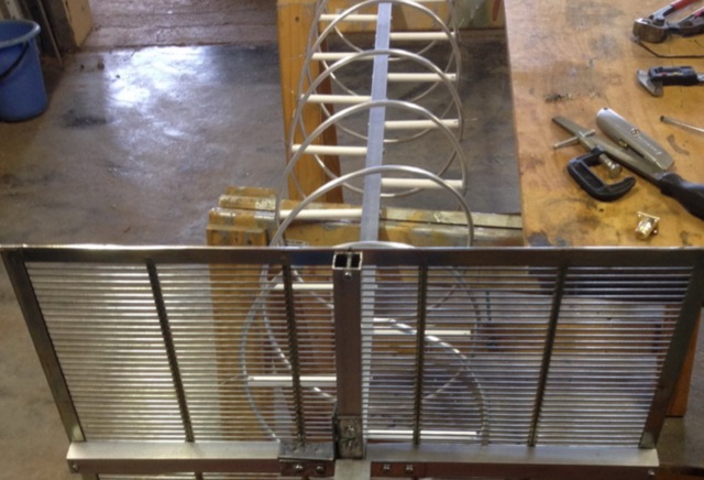
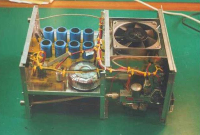 A 50 MHz stable and small power amplifier, suitable for portable and domestic use. This RF Power amplifier delivers 900W with used pair of tubes primary installed into amplifier.
 -
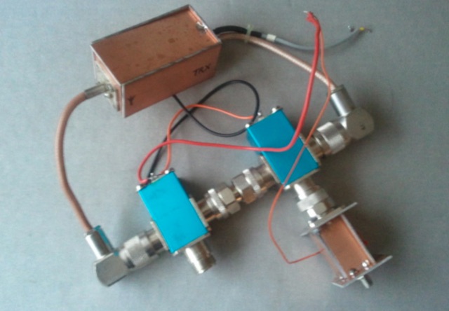
 This page details (in brief) the component changes to modify a Cybernet series 27MHz CB transceiver to 50MHz.
 -
 A ham radio home made preamplifier for 50 MHz and 70 MHz bands
 -
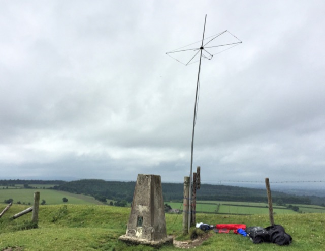 Bring the six meters with you during your hoilidays. This article features a portable moxon antenna for 50 MHz used for sota portable operatios
 -
 1260 MHz yagi antenna for ATV with a total Bandwidth (3 dB) 1240-1280 MHz and 10 dBd gain
 -
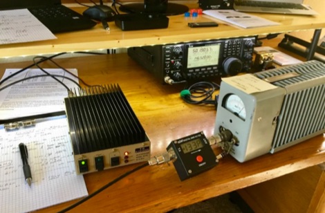 TE Systems 0510G 50 MHz meter amplifier set up for 10 watts in and 170 watts out.
 -
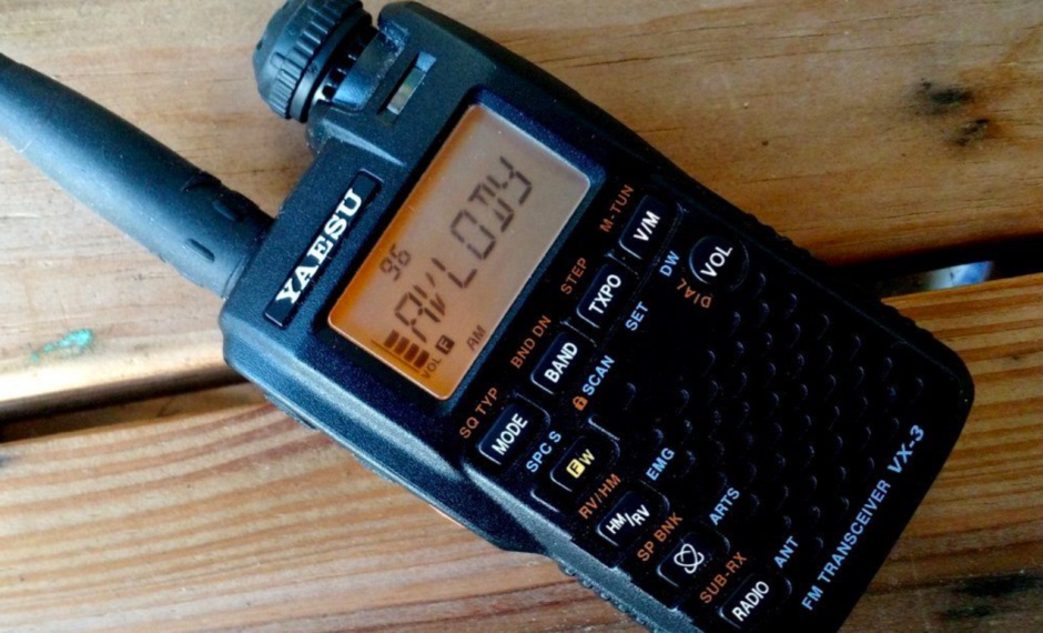 Review of Yaesu VX-3R 2 m/70 cm FM transceiver. Receives 0.5-999Mhz AM/FMN/FMW, Transmits 144-148 and 430-450Mhz VHF/UHF FM.
 -
 Dipole for 40m band. It is a simple linear loaded dipole feeded with 450-Ohm openwire feedline. Designed it for resonance at 7.050 MHz, can be tuned on 30m and 80m bands with an external antenna tuner. Build with simple electrical copper wire (2.5 mmq/13 awg) and two fishing poles with size of about 7 m/23 ft.