Search results
Query: HF bands
Links: 465 | Categories: 21
Categories
- Radio Equipment > HF Vertical Antenna > Butternut HF2V
- Technical Reference > Amplifiers > HF Amplifiers
- Operating Modes > HF Operations
- Technical Reference > Amplifiers > UHF Amplifiers
- Manufacturers > Antennas > VHF UHF Microwave
- Operating Modes > Aircraft scatter
- DX Resources > Beacons
- Antennas > CobWebb
- Technical Reference > Duplexers
- Antennas > Maria Maluca
- Antennas > Mobile
- Manufacturers > Antennas > VHF UHF Microwave > Mobile Antennas
- Manufacturers > Antennas > VHF UHF Microwave > Quad Antennas
- Manufacturers > Antennas > HF > Quad Antennas
- Radio Equipment > HF Vertical Antenna > Solarcon A-99
- Propagation > Sporadic E
- Manufacturers > Transverters
- Antennas > Vertical
- Manufacturers > Antennas > VHF UHF Microwave > Vertical Antennas
- Antennas > W3DZZ
- Antennas > Wire
-
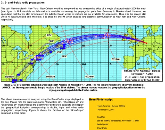 Thunderstorm effects on sporadic E propagation, Very long distance propagation in the 144 MHz band, Analysing the number of skips in multiple hop propagation
 -
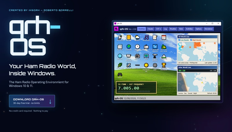 The **qrh-OS** application functions as a dedicated ham radio operating environment within Windows 10 and 11 systems, providing a consolidated platform for various amateur radio activities. It does not alter core system settings but instead presents a virtual desktop populated with specialized utilities and an integrated CAT radio system. This design aims to streamline the operator's workflow by centralizing tools often used for DXing, contesting, and general operating. Key features include a Telnet terminal for DX Cluster connections, real-time APRS tracking, and **CAT control** for transceivers, enabling one-click tuning from various integrated modules like Cluster, POTA, SOTA, WWFF, and Visual DX. The software also incorporates a worldwide Amateur Radio contest calendar, tools for Flora & Fauna activations, and displays for HF Low Bands Beacons and HF propagation conditions. Further utilities encompass a MeshCom Map, POTA Tunable, Reverse Beacons for WSPR network monitoring, SOTA Tunable, and a Timezone display. Visual DX offers an interactive globe showing DX stations and frequencies, while WebSDR/KiwiSDR access extends listening capabilities. An integrated IPTV player and real-time weather maps round out the comprehensive suite, all accessible within a single-window interface.
 -
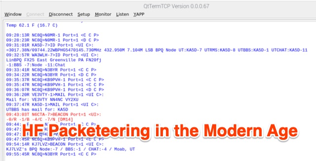 A brief overview of the current state of packet radio on the HF bands. In this comprehensive guide, the author navigates through HF packet radio, providing insights on the required equipment, protocols like Fx.25 and IL2P, and preferred ACDS segments. The post covers decoding and sending traffic, delving into optimal settings, recommended software, and common SSIDs. The author concludes by encouraging further exploration through additional reading and a Linux Packeteering series.
 -
 The E6AF DXpedition to Niue (OC-040) in 2019 successfully activated a rare DXCC entity, providing thousands of contacts for the global amateur radio community. Operations focused on maximizing QSOs across various **HF bands** and modes, significantly contributing to the DXCC program. The team, led by SP9FIH, meticulously planned antenna deployments and station setups, including a specific focus on **Fox-Hound mode** for digital operations, to ensure robust signal paths and efficient pile-up management. Operational details included specific schedules for CW, SSB, and digital modes, aiming to accommodate different time zones and propagation windows. QSL information and log search functionalities were made available post-operation, facilitating confirmation for thousands of contacts. The expedition encountered logistical challenges, including power supply failure and strict COVID-19 travel restrictions that delayed licensing. Despite these hurdles, the E6AF and E6CI stations provided valuable contacts from Niue, a sought-after location for many DXers.
 -
 This project introduces the Loggi, a hybrid antenna merging the wide frequency coverage of log-periodic dipole arrays (LPDA) with the high gain and front-to-back ratio (F/B) of Yagi antennas. Traditional LPDAs span broad frequencies with moderate gain and low VSWR, while Yagis provide high gain and F/B over narrow bands. By analyzing high-Tau LPDA designs, it was found they could nearly match the gain of VHF/UHF Yagis while maintaining excellent patterns, F/B, and front-to-rear ratios (F/R). Optimizing specific elements for target frequencies (e.g., 144.1 MHz) led to the Loggi, which uniquely features all driven elements without passive directors or reflectors. This design effectively functions as a narrowband optimized LPDA, with front elements acting like Yagi directors and rear elements like Yagi reflectors, thus enhancing gain and directional characteristics while retaining broad frequency versatility.
 -
 7MHz to 30MHz operation is achieved with a magnetic-mounted HF antenna designed for car roof deployment, capable of handling 100 Watts without an external antenna tuner. The design incorporates a large base-loading coil with multiple taps, allowing for frequency selection across various HF bands. This coil effectively increases the electrical length of a short telescopic antenna element, compensating for its inherent capacitance. Construction involves 3D-printed components for the coil former and support structures, though conventional building methods using plastic drainpipes are also suggested. The car body serves as the ground plane, with the coil assembly mounted on a 500mm square metal plate secured by super neodymium magnets. Protection under the magnets is advised to prevent vehicle scratches. Detailed instructions cover winding the 30-turn coil with 2.5mm diameter household electrical cable, assembling the 3D-printed parts, and making soldered connections. Taps are staggered every five turns for precise frequency adjustment. Performance examples include a 7913km contact to Japan using a 1.5m element and 100 Watts, demonstrating low-angle radiation and omni-directional pattern with minimal S-point loss compared to a full quarter-wave.
 -
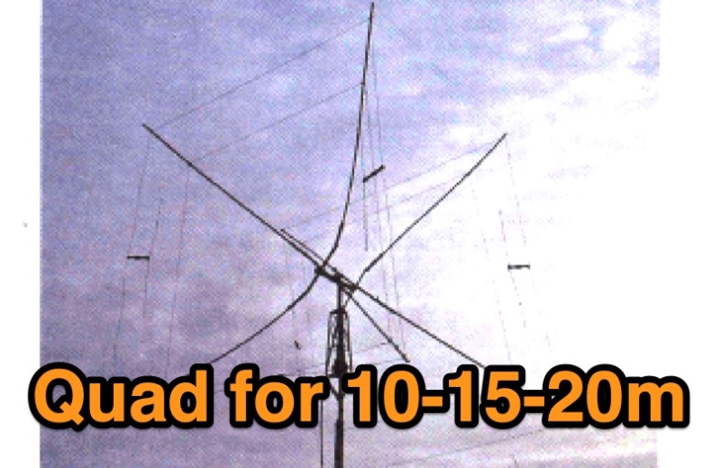 The Shrunken Quad antenna is a unique design that offers full-sized performance on the 10m and 15m bands while incorporating linear loading via a trap for operation on the 20m band. This design allows for effective communication in the HF spectrum, making it suitable for both casual operators and serious DXers. The quad configuration provides excellent gain and directivity, which is beneficial for contesting and long-distance contacts. Constructing the Shrunken Quad involves careful attention to dimensions and materials to ensure optimal performance. The antenna's compact nature makes it an excellent choice for limited space situations, allowing operators to enjoy the benefits of a quad without the need for extensive real estate. This project is ideal for amateur radio enthusiasts looking to enhance their station's capabilities with a versatile and efficient antenna system.
 -
 The document provides a detailed modification guide for the Zetagi HP201 SWR Wattmeter, converting it for HF amateur band usage. It replaces the original circuit with a Tandem Coupler based on the Sontheimer and Frederick directional coupler patent, enhancing accuracy and sensitivity. Key components include Murata toroid cores, scaling resistors, and a new calibration process. Challenges and solutions during the modification process are discussed, ensuring linear results across 160-10m bands. This guide also includes calibration instructions and theoretical insights into the coupler's operation.
 -
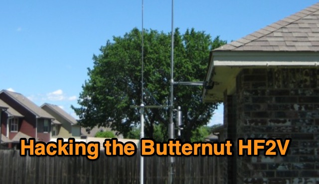 The Butternut HF2V, originally a two-band vertical antenna for 80m and 40m, was enhanced by the user to include 30m and 20m bands for better digimode DX work during the solar minimum. The additions used components adapted from the HF6V and innovative methods for the 20m addition, either through a parallel vertical element or a lower-mounted independent element, minimizing band interaction. This modified four-band antenna now supports high power across popular HF bands using a single feedpoint.
 -
 This project describes the construction of a W3HH (T2FD) antenna for HF bands (3-30 MHz). While less efficient than a tuned dipole, it offers broad frequency coverage with a maximum SWR of 3.4 and reduces QRM (noise) significantly. On the 80-meter band, it shows slightly weaker signals than a dipole but with improved signal-to-noise ratio. The design includes non-inductive resistors, a 13:1 balun, and a "frog ladder" transmission line. Though not a high-performance antenna, it is compact and versatile, making it ideal for wide-band HF communication. Article in French
 -
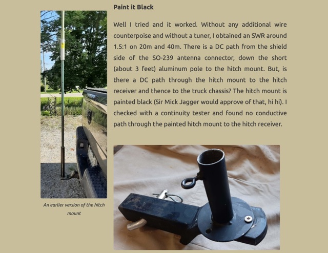 Experimenting and testing vertical antenna for HF bands on mobile operations.
 -
 This is a plan for an optimized element UHF Yagi Antenna for UHF Bands featuring a 9dBd forward gain, a 13 dB front-back ratio, and a bandwith of 10 MHz on the 430-440MHz range.
 -
 Learn how to design a Hentenna antenna, a portable asymmetrical double-loop antenna ideal for amateur HF or VHF bands. This page provides details on constructing and optimizing the antenna for maximum performance in DX communications. Discover how altering the antenna's vertical feed section can adjust the VSWR resonant frequency and how changing the support pole's position can alter the beam direction. Originally developed by Japanese 6-meter operators, the 'Hentenna' offers a unique design that allows for horizontal polarization when vertically oriented. Explore radiation patterns, VSWR charts, and antenna currents diagrams to optimize your antenna's performance for long-distance contacts.
 -
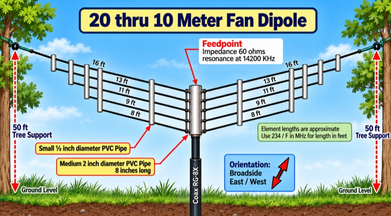 The 20-10 meter fan dipole antenna described here offers broadside East/West coverage, a characteristic I've found particularly useful for working DX across the Atlantic and Pacific from my QTH. This design connects multiple dipoles of varying lengths in parallel at a single feedpoint, enabling operation across 20, 17, 15, 12, and 10 meters without the need for an external antenna tuner or switching. The guide specifies element lengths for each band, constructed using 1/2 inch PVC pipe for the elements and a 2-inch PVC pipe for the 8-inch long feedpoint connector, ensuring a robust build. Key advantages highlighted include its multi-band coverage, simplified installation, cost-effectiveness, and improved efficiency compared to single-band alternatives. The antenna is horizontally polarized when deployed at a height of 50 feet, providing a favorable radiation pattern for long-haul contacts. Materials required are readily available, including PVC pipes, _RG-8X_ feedline, antenna wire, and guying rope, making it an accessible project for most hams. This _fan dipole_ project provides practical considerations for construction and tuning, aiming for optimal SWR performance across the target bands. The detailed instructions, coupled with the specified components, allow for a straightforward build, even for those with limited antenna building experience, yielding a capable HF antenna for the upper bands.
 -
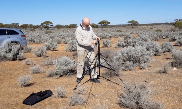 For amateur radio operators engaging in portable operations like SOTA or POTA, rapid deployment of an effective antenna system is paramount. This video resource details the assembly process for the Buddipole multiband dipole antenna, showcasing its components and how they fit together. Rob, VK5SW, systematically presents the mast, coil arms, radiating elements, and the VersaTee hub, emphasizing the modular design that allows for quick configuration changes across various HF bands. The demonstration highlights the antenna's adaptability for different operating environments, from a ground-mounted vertical to a horizontal dipole. The video illustrates the ease with which the antenna can be packed and deployed, making it a practical choice for activations where setup time is limited. The Buddipole's design facilitates efficient band changes and tuning, crucial for maximizing QSO opportunities during field operations.
 -
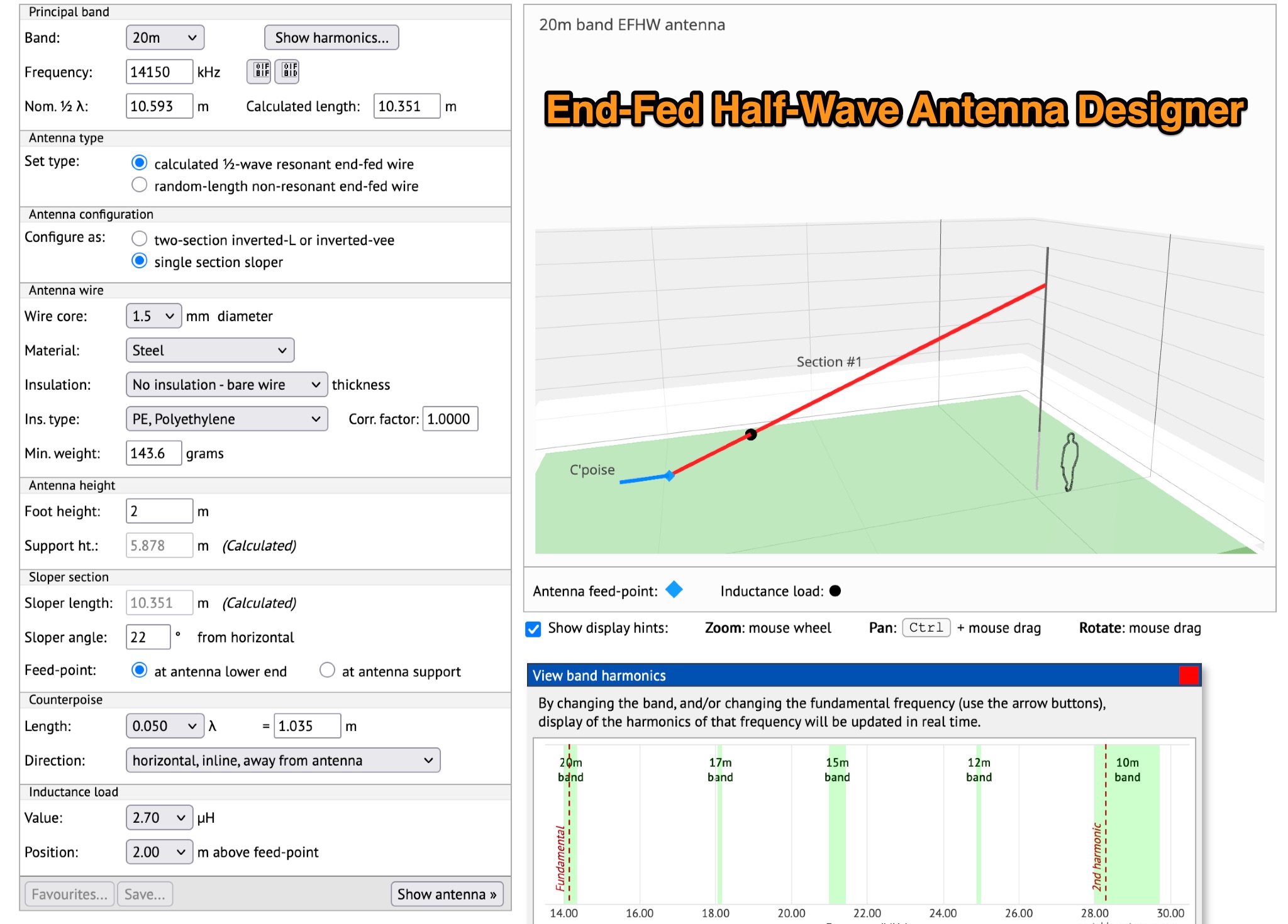 This page provides guidance on designing an End-Fed Half-Wave (EFHW) or Random-Length antenna for amateur HF bands, such as 80 or 40 meters. The content explains how to optimize the antenna for multi-band use and match it to a 50-ohm system using an unun. Hams can generate radiation patterns, VSWR charts, and antenna current diagrams for their customized antenna designs. Understanding how antenna dimensions affect performance is essential for successful field operations. The page caters to ham radio operators looking to build efficient and effective HF antennas for their stations.
 -
 This page delves into the debate surrounding the End-Fed Half-Wave (EFHW) antenna, exploring whether it is truly a multiband antenna without the need for a tuner. The author investigates the claims and criticisms surrounding these popular antennas, discussing their resonance on various bands and their efficiency for DXCC achievements. The content is valuable for hams interested in understanding the capabilities of EFHW antennas and their performance across different HF bands, with a focus on practical usage and real-world results.
 -
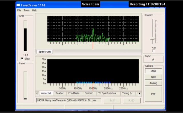 FreeDV uses an audio codec as a software based modem to decode and encode the voice and text data from your computer. The data is encoded and then is transmitted over the HF radio using AF signals that can then in turn be decoded by the receiving station.
 -
 Antenna patterns are all about interference. Presentation on wire antennas for HF bands. Dipoles, horizontal and vertical dipoles, effects of ground on radiation patterns, multi-band wires antennas. Knowing what you should expect from the radiation patterns for waves on your wires will help you choose what will work best for your needs. The principles of interference can lend insight into what to expect from a wire antenna.
 -
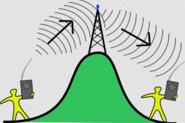 The most basic form of repeater receives communication on one frequency and re-transmits it on a different frequency, a process known as duplex communication. This capability significantly extends the range of handheld and mobile radios, as repeaters are typically situated at elevated locations with high-gain antennas and greater transmit power. Repeaters commonly operate with FM modulation on the VHF (30 MHz – 300 MHz) and UHF (300 MHz – 3 GHz) amateur bands, which are ideal for portable and mobile devices. Access to repeaters is often controlled by a CTCSS or PL tone, an inaudible signal that prevents the repeater from retransmitting background noise. This mechanism ensures efficient use of the frequency and prevents illegal continuous transmission. Canadian regulations, for instance, require an Advanced amateur radio license and an available frequency within the band to set up a repeater, each assigned a unique call sign and transmit frequency. Configuring a radio for repeater use involves knowing the repeater's transmit frequency, its receive frequency offset (e.g., -600 KHz for VHF or +5 MHz for UHF), and the necessary CTCSS tone. The article references resources like Repeater Book for locating repeaters and provides practical examples for initiating and concluding a basic repeater session, emphasizing clear identification and concise communication.
 -
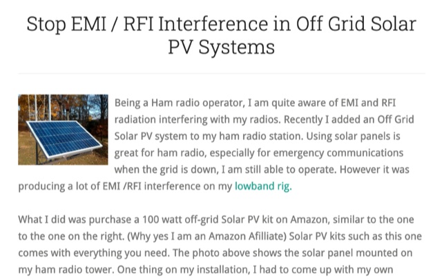 Stop EMI RFI Interference in Off Grid Solar PV Systems, in this article the author provides hints on tracking down the EMI or RFI source, shielding and grounding in order to eliminate interferences on the whole HF and VHF ham radio bands
 -
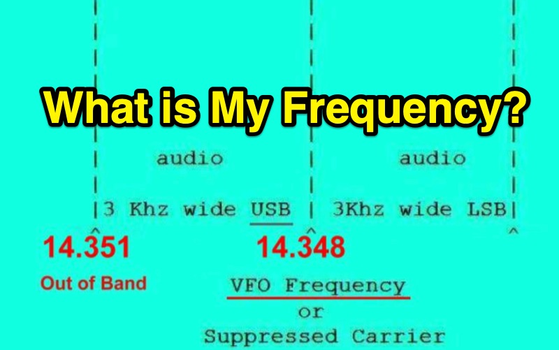 Single Sideband (SSB) operation requires careful attention to the relationship between a radio's displayed frequency (suppressed carrier) and the actual 3 kHz wide audio signal. This resource clarifies how Upper Sideband (USB) and Lower Sideband (LSB) signals occupy spectrum above or below the indicated frequency, respectively. It provides practical examples for General Class operators on the **20m** and **40m** bands, such as setting a VFO to 14.226 MHz for USB on 20m or 7.178 MHz for LSB on 40m, to maintain a safe margin from band edges. The resource emphasizes the critical importance of staying within allocated band limits to prevent out-of-band emissions, particularly when operating close to band edges. It includes relevant excerpts from **FCC Regulation Part 97**, specifically section 97.307, which details emission standards, necessary bandwidth, and spurious emission attenuation requirements. The text explains that unused sidebands are considered spurious emissions and notes that modern HF equipment typically exceeds the 43 dB spurious emission reduction standard, often achieving 60 dB or more.
 -
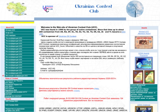 The Ukrainian Contest Club (UCC) website details contest activities, including a March 2026 contest calendar compiled by _UW3WF_ that excludes specific "exotic" tests, mini-tests, sprints, VHF competitions, and events organized by Russian entities. It lists major contests such as the ARRL International DX Contest, Stew Perry Topband Contest, and CQ WPX SSB Contest, providing dates, times, modes, bands (e.g., **10-160m**), organizers, log submission methods, and deadlines. The resource also highlights Ukrainian participation in various international contests, noting specific callsigns that represented the UCC, and acknowledges new Ukrainian records, such as UW5Y's new record in the ARRL DX CW Contest. The site presents contest results and rankings, including the top 20 Ukrainian contesters in the World Amateur Radio Contesting Association (WARCA) rating for 2019-2024, with _UW1M_ ranked #18 globally and #1 in Ukraine with **26,490.32** points. It also details the club's 12th place finish among 155 clubs worldwide in the CQ WPX Contest 2024 (CW + SSB). The resource includes information on WRTC 2026 participants from the club and lists members excluded due to collaboration with adversarial entities, reflecting the current geopolitical context.
 -
 Illustrates the construction of a mini ununtenna, focusing on practical design elements and component specifications for amateur radio operators. The guide covers the winding of the unun transformer, selection of appropriate ferrite core material, and integration of the radiating element. It specifies wire gauges, core dimensions, and connection points, providing a clear pathway for replication by hams. Compares the ununtenna's performance characteristics against other common wire antennas, highlighting its compact footprint and broadband capabilities. It discusses impedance matching considerations and offers insights into optimizing the antenna for various HF bands, making it suitable for portable operations or limited space installations.
 -
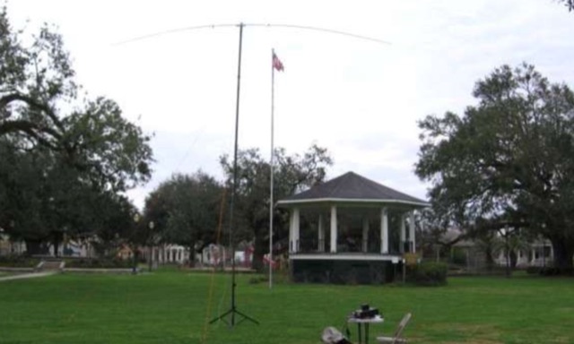 This document outlines the construction of a homebrew Buddipole antenna variant, designed for portable use and emergency services. The antenna utilizes telescoping whips and loading coils, enhancing its versatility across various HF bands. Key components include fiberglass rods, brass fittings, and Anderson Power Pole connectors, ensuring robust electrical connections. The design emphasizes non-inductive materials to minimize interference, while practical assembly techniques, such as epoxy and heat shrink tubing, are employed for durability. This variant aims to improve upon traditional Buddipole designs, offering greater strength and functionality.
 -
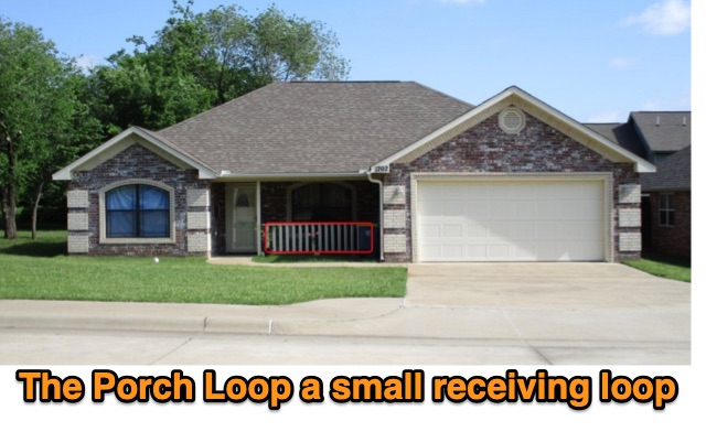 The small receiving loop (SRL) is a versatile and efficient antenna that can be simply built from common materials. It is designed for reception on the MF and HF bands and may be put in a variety of shapes and sizes. Despite its unusual installation, the porch loop in this case operated admirably, producing several DX spots on the 40m band. The SRL can be a great option for people looking to boost their reception on the MF and LF bands.
 -
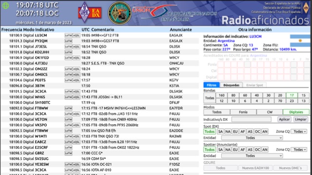 Operating on the HF and VHF bands, the URE WebCluster serves as a real-time DX spotting network for amateur radio operators. It aggregates DX spots from various sources, presenting them with detailed information such as DX callsign, frequency, mode, and spotter details. The platform integrates essential propagation data, including current solar indices like _K-index_ and _A-index_, alongside visual propagation maps, which are crucial for planning long-distance contacts. Users can submit new DX spots, contributing to the collective intelligence of the amateur radio community, and filter existing spots by band, mode, or callsign, enhancing operational efficiency. This resource enables operators to monitor band openings and identify active DX stations, significantly aiding in _DXCC_ pursuit and contest operations. The integration of solar-terrestrial data directly within the cluster interface allows for immediate correlation between propagation conditions and observed DX activity, a feature not universally present in all web clusters. By providing both raw spot data and contextual propagation information, the URE WebCluster offers a practical tool for real-time decision-making during operating sessions, allowing hams to quickly adapt to changing band conditions and target specific _DX_ entities.
 -
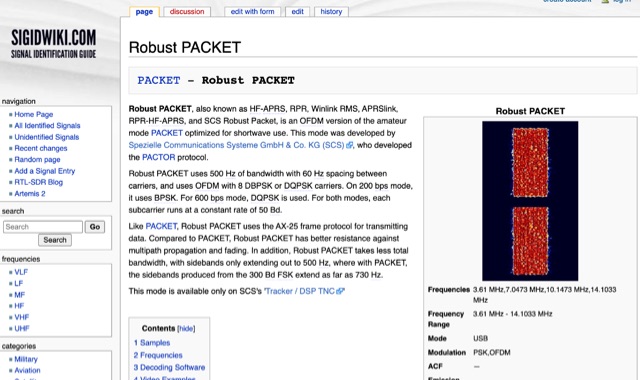 Robust PACKET, developed by Spezielle Communications Systeme GmbH & Co. KG (SCS), is an OFDM variant of the amateur PACKET mode specifically engineered for HF operation. This mode utilizes a 500 Hz bandwidth with 60 Hz carrier spacing, employing OFDM with 8 DBPSK or DQPSK carriers. It supports 200 bps using BPSK and 600 bps with DQPSK, with each subcarrier operating at a constant rate of 50 Bd. Robust PACKET leverages the AX-25 frame protocol for data transmission, similar to standard PACKET. Compared to traditional PACKET, Robust PACKET demonstrates enhanced resilience against multipath propagation and fading effects, critical for reliable HF communications. It also exhibits a more efficient spectral footprint, with sidebands extending only to 500 Hz, whereas 300 Bd FSK PACKET can produce sidebands up to 730 Hz. Operational frequencies for Robust PACKET include 3.61 MHz, 7.0473 MHz, 10.1473 MHz, and 14.1033 MHz, with specific regional frequencies also documented. Decoding software options for Robust PACKET include Wavecom W-Code and Wavecom W-Spectra. The mode is primarily supported by SCS's 'Tracker / DSP TNC' hardware.
 -
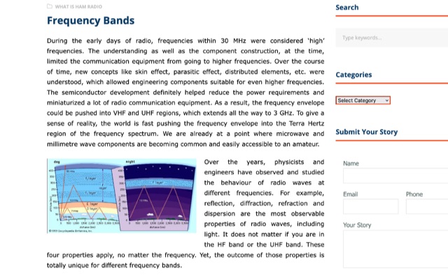 During radio's early days, high frequencies were under 30 MHz due to technical limitations. As understanding grew, components improved, allowing for higher frequencies like VHF and UHF up to 3 GHz. The HF band's long wavelengths provide unique propagation challenges influenced by solar activity. VHF and UHF bands face diffraction and reflection issues but offer diverse applications, from amateur radio to 5G and GPS technologies.
 -
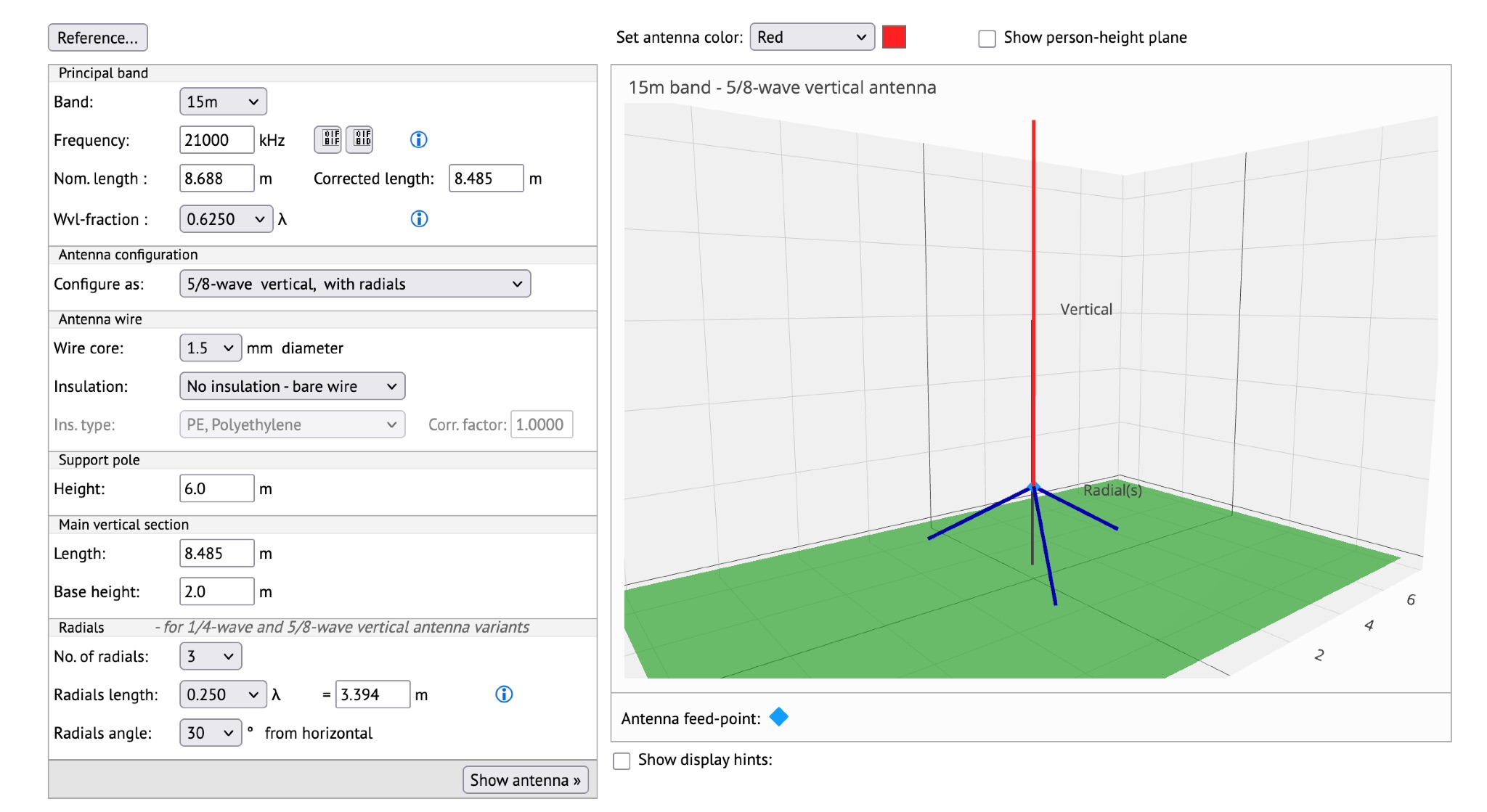 This page offers a tool for hams to design vertical antennas for portable use on different HF/VHF/UHF bands. Vertical antennas provide omni-directional transmission and reception, making them ideal for DX contacts. By adjusting the antenna's dimensions and viewing radiation patterns and VSWR charts, hams can optimize performance in various terrains. The tool also accounts for the impact of sloping ground on elevation radiation patterns. Perfect for hams looking to enhance their portable radio setups and improve long-distance communication.
 -
 This project details the development of a modular direct conversion (DC) receiver designed for experimental flexibility in amateur radio and HF signal listening. The mainframe integrates a diplexer, DBM, and AF amplifier, supporting interchangeable local oscillator and antenna filtering setups. A tunable passive HF preselector complements QRP Labs bandpass filters for enhanced signal reception. Utilizing a NanoVNA for precise tuning, the receiver achieves improved signal-to-noise ratios across amateur and non-amateur bands, making it a versatile platform for further RF experimentation.
 -
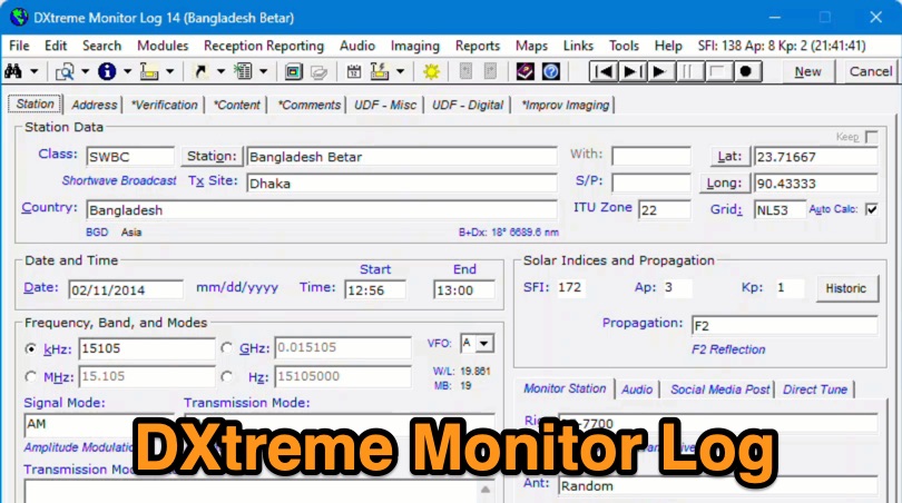 Demonstrates the capabilities of DXtreme Monitor Log 14, a specialized software application designed for radio spectrum monitoring and logging. The resource details its core functionality, which includes logging stations across various bands and supporting multiple transmission modes such as AM, CW, FM, LSB, USB, and RTTY. It highlights features like the ability to select country formats for new databases and the **Schedule Checker** tool, which assists users in identifying broadcast stations for monitoring. The software facilitates tracking **Maidenhead grid squares**, particularly useful for VHF and UHF monitoring activities. It also supports QSL management and offers tools for efficient contact logging, catering to both amateur radio operators and shortwave listeners. Specific information includes its version number, Monitor Log 14, and its utility for DXers and other radio enthusiasts in managing their monitoring experiences and logging contacts effectively.
 -
 This page provides information on how to design an Off-Center-Fed Dipole (OCFD) antenna, suitable for amateur HF bands like 80 meters or 40 meters. The antenna design allows for VSWR minima on multiple bands, making it a good choice for multi-band use. Learn how to create an OCFD antenna in either flat-top or inverted-Vee form using a single support. The page also offers tools to generate radiation patterns, VSWR charts, and antenna current diagrams for your specific antenna design, helping hams understand performance factors. Ideal for ham radio operators looking to build their own effective antennas.
 -
 Understanding radio wave propagation is fundamental for effective HF communication, and this guide from the Galway Radio Club elucidates the principles behind _Near Vertical Incidence Skywave_ (NVIS) operation. It begins by contrasting NVIS with line-of-sight and surface wave propagation, highlighting its utility for reliable regional coverage, particularly in challenging terrains or within the skip zone. The document explains how NVIS leverages high-angle radiation, refracting signals from the ionosphere to return to Earth within a circular region, typically up to **650 km** (400 miles) from the transmitter. The guide delves into critical factors influencing NVIS, such as the _critical frequency_ (Fo) and the Maximum Usable Frequency (MUF), emphasizing their dependence on solar activity, time of day, and season. It provides practical advice on frequency selection, noting that 40 meters is often the highest daytime NVIS band, with 60 meters and 80 meters favored as darkness falls. The author, EI5DD, suggests using an ionogram for real-time propagation data, considering it more reliable than generic ham-clocks. Antenna considerations are also covered, recommending dipoles, inverted vees, or phased dipoles positioned 0.1 to 0.25 wavelengths above ground for optimal high-angle radiation. The document mentions mobile NVIS setups, including military configurations and commercial options like the Barrett Communications roof-rack antenna, which can cost around **£2000.00**. It concludes by reinforcing NVIS as an essential technique for national emergency communications, with 5 MHz (60m) and 80 meters being primary bands for daytime and nighttime operations, respectively.
 -
 Effective suppression of harmonics and parasitic radiation from HF transmitters is crucial, especially with the increasing sensitivity of VHF/UHF radio channels to interference. This project details a hybrid low-pass filter (LPF) designed to operate across the HF bands up to 51 MHz, making it suitable for 6-meter band operations while providing deep VHF/UHF suppression. The design addresses the challenge of modern interference landscapes, where even microvolt-level signals can disrupt wireless sensors and other simple VHF/UHF receivers. The filter utilizes a single elliptic link, combining high cutoff steepness with robust suppression in the hundreds of megahertz range. A key feature is the use of only two standard capacitor values, simplifying construction and component sourcing. The article provides a detailed schematic, performance characteristics, and _RFSim99_ model file, demonstrating a reflection coefficient S11 below 0.017 (VSWR < 1.03) across 1-51 MHz, ensuring minimal degradation to the antenna system. Construction notes include coil winding specifications and capacitor selection guidance, with recommendations for _FR-4_ assembly. Two capacitor sets are presented, with the first variant recommended for its lower RF current demands, keeping currents below 3 A at 1 kW passing power at 51 MHz. Fine-tuning involves adjusting frameless coils, with considerations for capacitor tolerance and high-frequency capacitance measurement accuracy.
 -
 VE1ZAC's analysis details the performance of **MFJ927** and **SGC239** autotuners with portable HF vertical antennas, specifically comparing 31 ft and 43 ft configurations. The resource originated from challenges encountered during a Maritime QSO Party roving operation, necessitating a lightweight and easily deployable antenna system. Target bands for the contest included 80, 40, 20, 15, and 10 meters, with a maximum power handling of 100 W CW. The author utilized a 30-foot carbon fiber push-up pole to support a vertical wire element, noting its 2 lb weight and reliability. EZNEC modeling was employed to predict performance, showing favorable results for a 30-foot vertical with elevated radials, particularly on 40 and 20 meters. Feedpoint impedance measurements, taken with an AIM4170C, are presented for various HF bands, both with and without a 41-foot RG6 stub designed to reduce reactance on 80 and 20 meters. The stub significantly improved matching on these bands, easing the tuner's workload. Operational tests revealed issues with the MFJ927's reliability during contest setup, leading to reliance on the K3's internal tuner. The SGC239, tested post-contest, performed flawlessly. A detailed side-by-side comparison covers mechanical aspects, connection options, power bias, impedance range, board quality, and documentation. Modifications to the MFJ927, including a new aluminum case, white paint for heat reduction, and upgraded impedance-measuring resistors, are also described.
 -
 RUssian DXpedition Team is glad to annonce a trip to Kindom of Eswatini (Swaziland).Active on HF Bands 7-22 October 2021
 -
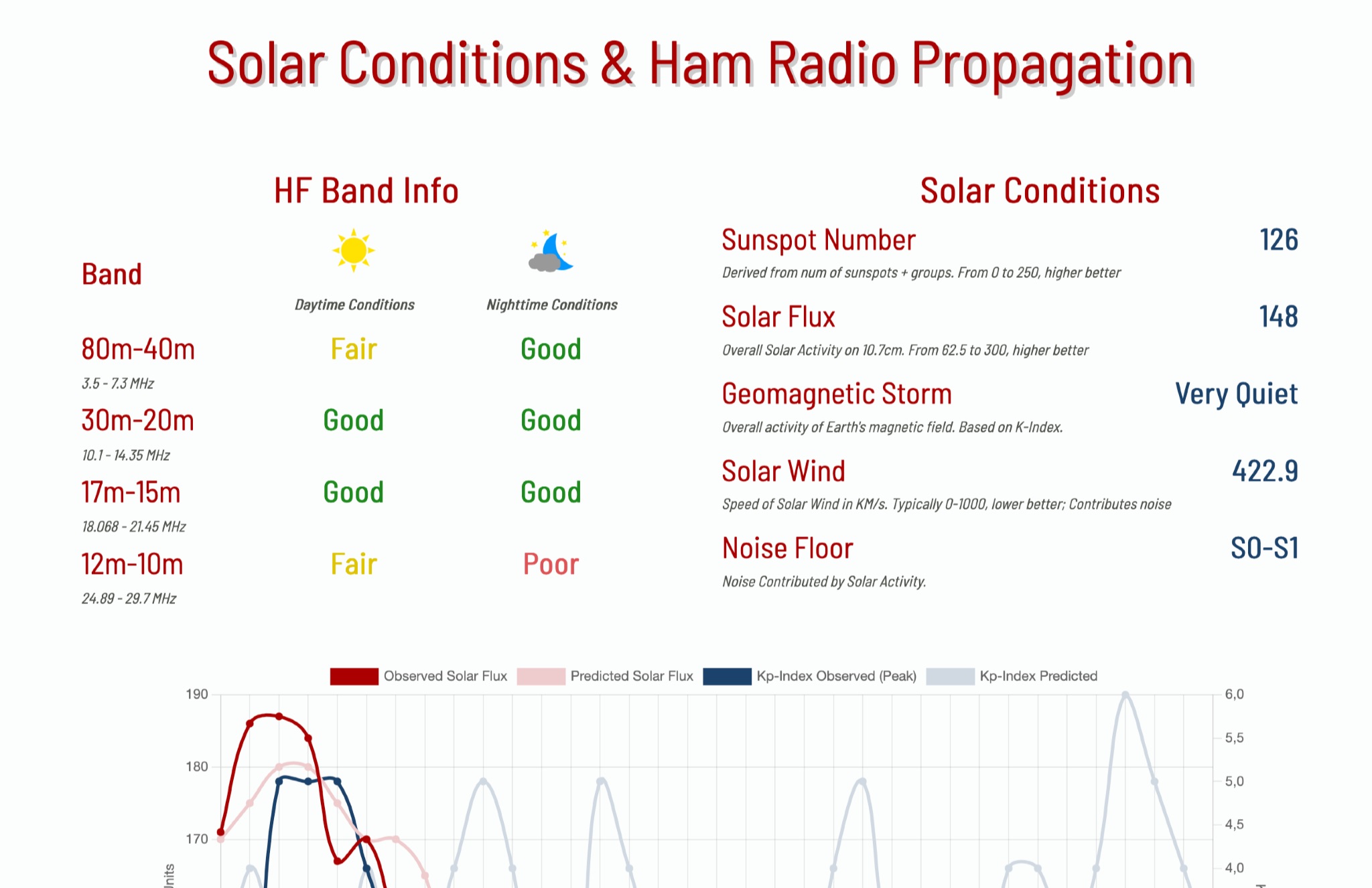 This page provides information on solar conditions and their impact on ham radio propagation, specifically focusing on the HF bands. A daily graph show the predicted solar flux and Kp Indexes
 -
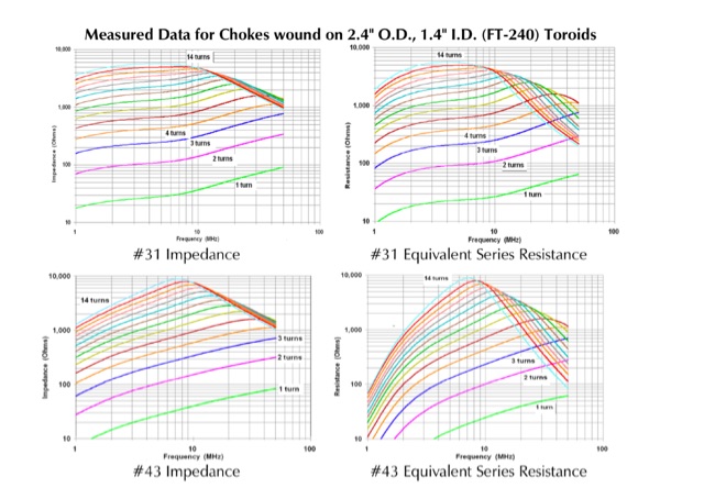 FT-240 toroids measurements. The data was measured using well-calibrated HP instrumentation. All plots have been adjusted to a frequency range of 1-100 MHz on the horizontal axis and a resistance/impedance range of 10-1,000 ohms on the vertical axis. This adjustment facilitates comparison among different materials and aids in determining their suitability for use on the HF ham bands.
 -
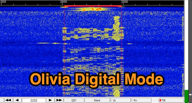 The Olivia digital mode, a **Multi-Frequency Shift Keying (MFSK)** radioteletype protocol, is specifically engineered for robust communication under difficult propagation conditions on shortwave radio bands from 3 MHz to 30 MHz. Developed by Pawel Jalocha in 2003, Olivia signals can be decoded even when the noise amplitude exceeds the digital signal by over ten times, making it highly effective for transmitting ASCII characters across noisy channels with significant fading and propagation phasing. Early on-the-air tests by Fred OH/DK4ZC and Les VK2DSG on the Europe-Australia 20-meter path demonstrated intercontinental contacts with as little as one-watt RF power under favorable conditions. Common Olivia modes are designated as X/Y, where X represents the number of tones and Y is the bandwidth in Hertz, with examples including 8/250, 16/500, and 32/1000. The resource clarifies that Olivia, unlike some other digital modes, produces a constant envelope, allowing RF power amplifiers to achieve greater conversion efficiencies and making it less prone to non-linearity. Operators are advised that **Automatic Level Control (ALC)** can be set higher than no meter movement for MFSK modulation, as long as it's not driven past its high limit, contrary to common misinformation about other digital modes. The Olivia community encourages voluntary channelization on suggested calling frequencies, such as 14.0725 MHz for 8/250, to facilitate initial contacts, especially for signals below the noise floor. The Olivia Digital DXers Club provides links to Groups.io, Facebook, and Discord for community engagement and offers details on QSO parties.
 -
 This project involved designing a 7-pole Chebychev broadcast band filter to address severe interference issues caused by a new horizontal loop antenna on the KN-Q7A transceiver. The interference overwhelmed the transceiver’s front end, so a custom filter with a 3.5 MHz cutoff was built using silver mica capacitors and type 6 T130 toroidal cores. Encased in a diecast box with SO239 sockets, the filter blocks strong signals from the broadcast band, achieving over 100 dB attenuation. Tested up to 100W, it reduces interference effectively while maintaining low insertion loss across HF bands.
 -
 The POCKET TUNER V1.1 is a highly compact HF T-Match antenna tuner designed for QRPp and QRP portable operations. With a credit card-sized form factor, it is tailored for low-power setups, supporting HF bands from 10m to 40m. The tuner features a unique design using rotary switches for precise capacitor adjustments, allowing tuning in small increments. Its inductance selection is optimized for various bands, ensuring efficient performance. Equipped with a resistive tuning indicator, it protects the transmitter by reducing SWR during adjustments. This versatile and portable tuner is ideal for field operations, enabling efficient antenna matching for low-power rigs.
 -
 An FT-817 ceased transmission on the VHF 2m band, despite the other HF, UHF, and 50 MHz bands operating correctly. Suspecting an excess of input signal during FT-8 mode transmission, they conducted measurements with an oscilloscope, revealing a burnt-out PIN diode, identified as D3003, type HSU277, on the PA unit board. Following the replacement of this surface-mounted diode, their FT-817 resumed operation on the 144 MHz band.
 -
 Operating amateur radio repeaters involves understanding frequency offsets, CTCSS tones, and the basic signal flow through a repeater system. This resource details the fundamental concepts of repeater operation, including the distinction between input and output frequencies, the role of **CTCSS (Continuous Tone-Coded Squelch System)** for access, and the typical frequency bands utilized for local communication. It clarifies terms such as "simplex" versus "duplex" operation and provides a diagram illustrating the signal path from a handheld transceiver to a repeater and back to another station, emphasizing the range extension repeaters offer. The article further explains practical aspects like identifying a repeater's offset (e.g., +600 kHz for 2-meter band) and the necessity of programming the correct tone. It compares the operational benefits of using repeaters for local communication over direct simplex contacts, highlighting how repeaters overcome line-of-sight limitations. The content is structured to assist new licensees in confidently making their first repeater contacts, providing a foundational understanding of how these critical infrastructure components facilitate wider area coverage for VHF/UHF amateur radio.
 -
 Demonstrates the construction of an active loop converter specifically designed for the Low Frequency (LF) bands, addressing common localized noise interference in LF reception. The design integrates a sharply tuned circuit and a tuned loop antenna, utilizing the loop as the sole tuned inductive element. By applying positive feedback, the converter significantly increases the loop's effective Q, achieving factors between 1000 and 2000, which sharpens tuning and reduces noise. The circuit employs an _NE602_ mixer stage, feeding its output to an HF receiver, with a crystal-locked local oscillator at 4 MHz. A 20-turn, 0.8-meter square loop antenna with 500 uH inductance is detailed, connected via 2 meters of figure 8 flex cable. The converter offers three selectable frequency bands: 195-490 kHz, 150-220 kHz (including the New Zealand amateur band), and 128-160 kHz (covering the European amateur band). Performance measurements indicate an effective 3dB bandwidth of approximately 100 to 200 hertz at 200 kHz. The article provides insights into component selection, including an _LF353_ op-amp and a trifilar wound transformer on a ferrite core. Sensitivity figures are presented, showing 7.5 uV of converted output per 1 uV/meter signal strength into a 50-ohm load, or 37.5 uV into an _FRG7_ receiver, highlighting its capability to extract weak signals from noise.
 -
 Ham radio communication in the VHF and UHF bands, which was previously dominated by analog Frequency Modulation (FM), is increasingly incorporating Digital Voice (DV) modes. DV transceivers digitize audio and offer benefits like as signal integrity, encoded caller ID, and bandwidth savings. Today D-STAR, DMR and Yaesu System Fusion (YSF) are popular DV formats, each with its own set of features but mainly incompatible with the others. Internet access with Voice Over Internet Protocol (VoIP) expands DV communication worldwide. Repeaters and personal hotspots expand DV capabilities, enabling seamless worldwide connections. However, implementing DV frequently necessitates learning new technologies and negotiating network complexity.
 -
 The RI1FJL DXpedition to Franz Josef Land, planned for August 2026, will deploy at least five high-power stations operating 24/7 across all **HF bands** for 15 days. The team of six operators, including R7AL and UA3QLC, will depart Murmansk on August 7, 2026, aboard a 20-meter sailing yacht, aiming for Heiss Island (IOTA: EU-019, QTH Loc.: LR80tn, CQ zone: 40, ITU zone: 75). Operating modes will encompass CW, SSB, and FT8, with specific FT8 frequencies like 1836.0 kHz and 14095.0 kHz designated for MSHV software. Equipment includes EE SUNSDR2 DX and Elecraft K3 transceivers, paired with Expert 1.3K-FA power amplifiers, and a variety of antennas such as Spiderbeams and phased GPs for 40m, 80m, and 160m. The expedition emphasizes working distant regions and low-power stations, acknowledging the challenging Arctic conditions with average temperatures around 1-3°C below zero. The logistical planning includes securing accommodation at the Geophysical Polar Observatory on Heiss Island and navigating potential ice conditions for zodiac landings. QSL information specifies ClubLog uploads at least daily, with OQRS available for direct and bureau QSLs. Donors contributing $10 or more receive fast LoTW confirmation and direct QSL cards, while Platinum Donors of $100+ will have their callsigns featured on the QSL card. A special plaque is offered for two QSOs with RI1FJL on different bands or modes.
 -
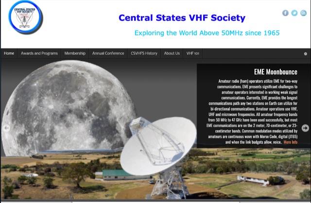 The Central States VHF Society, Inc. (CSVHFS) is a not-for-profit organization chartered in the state of Missouri. It was begun in the mid-1960s to foster amateur radio operation on the bands above 50 MHz.
 -
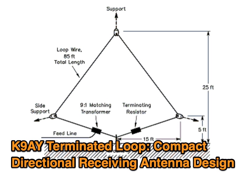 This resource presents the design and characteristics of the K9AY Terminated Loop, a compact directional receiving antenna system. The document details the antenna's physical and electrical configuration, consisting of a wire loop, a 9:1 impedance-matching transformer, and a terminating resistor. It describes how the antenna achieves directionality, favoring signals from the feed point end and rejecting signals from the terminating resistor end by several S units. The system is designed for low-band operation, specifically mentioning its application for improving reception on bands where space is a constraint. A four-direction system, utilizing two loops oriented at right angles with a relay-controlled switching system, is discussed. The resource includes a comparison of the K9AY loop's footprint to that of an equivalent EWE array, indicating the K9AY system requires approximately 1/7 the area while maintaining similar directional patterns. The design prioritizes signal collection sufficient for use with modest preamps, such as those integrated into HF transceivers. The article was originally published in QST in 1997.
 -
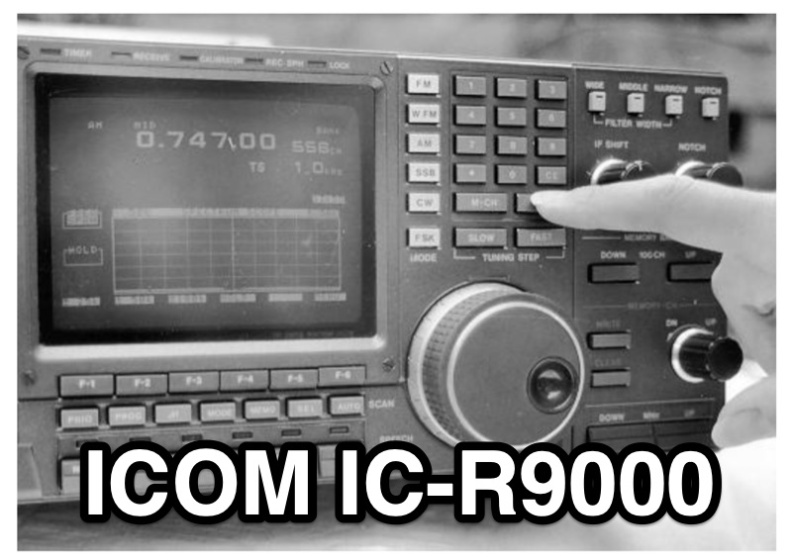 Assessing the ICOM IC-R9000 communications receiver, this review details its operational parameters and user experience for radio enthusiasts. Introduced in 1985, the IC-R9000 covers a broad frequency spectrum from 0.1 MHz to 1999.8 MHz, making it suitable for a wide array of listening activities from medium wave (MW) to VHF/UHF. Key performance metrics include a dynamic range of **102 dB** with the narrow SSB filter, crucial for discerning weak signals in crowded bands, and its substantial physical dimensions of 424 x 150 x 365 mm and 20 kg weight. The receiver's architecture supports various modes, though it notably lacks synchronous detection, a feature often desired for improved AM reception under fading conditions. It incorporates 1000 memory channels and robust scanning capabilities, facilitating efficient monitoring across its extensive frequency range. This analysis provides insights into the IC-R9000's capabilities and limitations, offering a historical perspective on a significant piece of amateur radio and shortwave listening hardware.