Search results
Query: 102
Links: 30 | Categories: 0
-
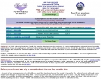
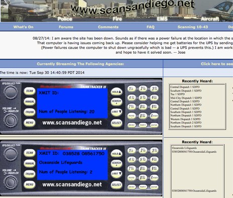 Three live police scanner streams are offered, broadcasting twenty-four hours a day from San Diego County. KE6CBF, the site's operator, provides real-time communications from agencies like the San Diego Police Department (SDPD), San Diego Fire-Rescue Department (SDFD), Sheriff, California Highway Patrol (CHP), and Air Traffic Control (ATC). Beyond the live audio, the platform includes a community forum for scanner enthusiasts. It also provides resources such as FAQs, _10-43_ information pages, and police codes to assist listeners in understanding the transmissions. The site aims for high-quality streaming audio with minimal downtime, supported by user donations. Powered by technologies like PERL, mySQL, ICECAST, APACHE, and LINUX, the site is designed for optimal viewing at **1024 x 768** resolution or higher.
 -
 The G5RV antenna, with an overall length of **31.10m (102ft)**, functions as a 3/2-wave on 20 meters when installed horizontally at 12m (39ft), exhibiting a resonant frequency of 14.150MHz and an approximate resistance of 80 ohms. Its 10.36m (34ft) stub line, designed as a 1/2-wave on 14.150MHz with a 0.97 velocity coefficient, acts as an impedance transformer across other bands, aiming for multiband operation without traps. On 20m and higher frequencies, the G5RV demonstrates improved gain compared to a standard dipole, attributed to the _collinear effect_ from multiple 1/2-waves along the wire. The original design sought a multiband solution for limited spaces, often requiring an Antenna Tuning Unit (ATU) for effective operation across bands like 80, 40, 30, and 20m, particularly with modern solid-state PAs. Variants, such as the F8CI modification, incorporate a 1/4 current balun at the stub line's base for symmetrical-to-asymmetrical transition, known as a _remote balun_. Proper flat-top or inverted-V installation is critical for maintaining symmetry and collinear gain, with inverted-V apex angles below 120° progressively diminishing higher-band performance.
 -
 G5RV 40m Beam Antenna. Adding a 28 ft. piece of vertical wire to one end of a 102 ft. center-fed dipole turns it into a 40m beam with a very wide beamwidth
 -
 Multi-band centre-fed antenna capable of very efficient operation on all HF bands, specifically designed with dimensions which allow it to be installed in gardens and other open spaces which accommodate a reasonably-straight run of 31.1m (102 ft) for the flat-top standard model.
 -
 Over 40 years of experience inform the reviews and commentary presented on Dave's Radio Receiver Page, covering a wide array of radio receivers and transceivers. The resource details specific models such as the **ICOM IC-R8600** SDR Communications Receiver, which is lauded as Icom's best wide-band receiver, even surpassing the IC-R9500 in performance. Other notable reviews include the ICOM IC-7300 HF Transceiver, highlighting its direct sampling SDR technology and spectrum scope capabilities, alongside numerous models from Japan Radio Co. (JRC), Kenwood, Yaesu, and various portable shortwave receivers. The content provides practical insights into the performance and characteristics of each radio, often drawing comparisons between models. For instance, the early issues with the AOR AR7030 receiver's Bourns mechanical encoders are thoroughly documented, including AOR's eventual switch to higher-quality Alps encoders. The page also features reviews of antennas like the MFJ-1026 Noise Canceling Signal Enhancer and various power supplies, offering a holistic view of radio monitoring setups. The author's "2 ear / 2 eye method" emphasizes real-world listening experiences over laboratory measurements, providing a unique perspective on equipment utility.
 -
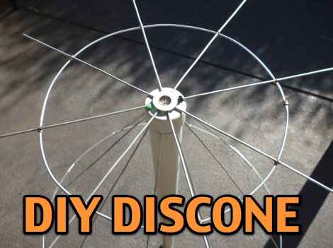 A DIY discone antenna project made to improve receiveing performance of an RTLSDR receiver.
 -
 Over 70 international contests are supported by YPlog, a Windows-based logging and radio control program designed for amateur radio operators. This software integrates with various digital mode applications like _WinPSK_, _HamScope_, and _MMTTY_, facilitating partially automated log entry for modes such as PSK31, CW, and RTTY. It provides comprehensive logging capabilities including QSL label printing, beam headings, and dup-checking, alongside award tracking for DXCC, ITU/CQ zones, IOTA, Grid Locators, and Counties. The program offers advanced contesting features, including multi-multi or multi-2 networked operations with automatic log data sharing, multiple Cabrillo submission formats, and configurable CW keyboard layouts. Device support extends to TR-compatible CW keying, SO2R control with Top-Ten devices like the DX-DOUBLER, and internal W9XT digital voice keyer integration. YPlog is notable for its support of the _OK1RR DXCC_ country resolution files, providing a robust historical DX compendium. Beyond logging, YPlog includes two freeware utilities: one for computing design parameters for coaxial traps and another for displaying and printing azimuth and Mercator maps from the operator's QTH. The software runs on Windows 95/98/ME/NT/2K, with a recommended screen resolution of 1024x768. Registration costs **$50.00 US** to unlock all features, including full contesting capabilities and rotator control.
 -
 The original G5RV antenna system consists of a center-fed horizontal 102' wire plus a 34' length of open-wire 525-Ohm feeder. Louis Varney, the antenna system's developer, intended two other features. Learn more at Cebik website
 -
 HF QSO/QSL/Award managment, ADIF Import/Export, full version free to everybody. Requires Access 97 or Access 2000 (with JPEG and TIFF filter installed), screen resolution 800x600/1024x768
 -
 The G5RV antenna, a popular multi-band wire antenna, typically employs a center-fed design with a specific length of 300-ohm or 450-ohm open-wire line acting as an impedance transformer, feeding a coaxial cable run to the shack. Its overall length for 80-10 meters is approximately 102 feet (31 meters) for the flat-top section, with a 34-foot (10.36 meter) matching section. The original design by Louis Varney, G5RV, aimed for efficient operation on 14 MHz (20 meters) as a 3-half-wave antenna, with the matching section providing a good match to 50-ohm coax on that band. While the G5RV offers multi-band capability, its performance varies across bands, often requiring an antenna tuner for optimal SWR on bands other than 20 meters. The matching section's length is critical for its impedance transformation properties, influencing the feedpoint impedance presented to the coaxial cable. Variations like the G5RV Junior and ZS6BKW utilize different flat-top and matching section lengths to optimize performance for specific band sets or to achieve a lower SWR without a tuner on certain bands, demonstrating the adaptability of the basic G5RV concept.
 -
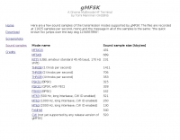 Sound samples of the transmission modes recorded at 11025 samples per second, mono and the message in all of the samples is the same: "the quick brown fox jumps over the lazy dog 1234567890".
 -
 The MCP-F6/F7 software facilitates memory channel and menu data creation for the Kenwood TH-F6A, TH-F7A, and TH-F7E transceivers. It operates on _Windows_ XP (SP3+), Vista (SP2+), Windows 7 (RTM+), Windows 8 (RTM+), Windows 8.1 (RTM+), Windows 10, and Windows 11. System requirements include a CPU faster than the OS recommendation, RAM exceeding the OS recommendation, and **2 MB** of free hard drive space. Display resolution must be XGA (1024 x 768) or higher. Connectivity to the transceiver requires an optional PG-4Y (RS-232) or KPG-22U (USB 2.0) programming cable. The KPG-22U cable necessitates a virtual COM port driver installation. The software supports COM1 through COM20 for RS-232 communication. Installation requires administrator privileges and involves executing "setup.exe" from the extracted MFX101.zip archive. Uninstallation is performed via the Control Panel's "Uninstall a program" function or by re-executing "setup.exe." Created data files are not removed during uninstallation and require manual deletion. The software version is **1.01**. DXZone Focus: Kenwood TH-F6 F7 | Memory Management | Windows | RS-232
 -
 The FTBVR5K software facilitates comprehensive memory management for the Yaesu VR-5000 scanning receiver, supporting operations such as modifying, moving, adding, deleting, masking, and unmasking individual memories. It allows for importing and exporting memory definitions via CSV files, sorting memories by frequency or name, and identifying duplicate frequencies within the receiver's configuration. The program also supports the creation and modification of bank definitions, management of PMS (Programmable Memory Scan) definitions, and adjustment of PMS scanning ranges. Additionally, users can print detailed reports of memories, banks, PMS definitions, rig settings, and S.CALL details, with visual cues like red highlighting for masked memories and yellow for the priority channel. FTBVR5K provides functionality to alter values within the VR-5000's Set and Config menus, and to change S.CALL station names and frequencies. The application operates on standard Windows PCs, including Windows XP, Vista, 7, 8, and 10, requiring an available COM port for transceiver connection, which can be a conventional serial port or a USB adapter. A minimum screen resolution of 800 x 600 is supported, with 1024 x 768 recommended for optimal usability.
 -
 High speed silicn diodes work well as RF switches. This article describes how to use diodes for selecting two or more filters ARRL QST article by W1FB
 -
 Choosing the right antenna for you, by Lewis G. McCoy W1ICP
 -
 The G5RV multiband HF antenna, designed by Louis Varney (G5RV) in 1946, is a popular compromise antenna offering good overall performance on most HF bands when paired with an external antenna tuner. The basic full-size G5RV measures 102 feet across the top for 80 through 10 meter operation and is fed at the center via a 34-foot low-loss feed-stub. This interaction between the radiating section and the feed-stub facilitates matching across 80-10 meters with a standard tuner, often eliminating the need for ladder line directly to the shack. The antenna's design center frequency is 14.150 MHz, configured as a 3/2-wave dipole on 20 meters, with its 102-foot length derived from long-wire antenna formulas. Construction details emphasize the matching section, which can be open wire, ladder line (window-type), or TV twin lead. Each type has a specific velocity factor (VF) affecting its physical length for an electrical half-wave on 14 MHz; for instance, open wire requires 33.7 feet (VF 0.97), ladder line 31.3 feet (VF 0.90), and TV twin lead 28.5 feet (VF 0.82). The article provides formulas for calculating these lengths and discusses the antenna's behavior on individual bands, from 3.5 MHz where it acts as a shortened dipole, to 28 MHz where it functions as two three-half-wave long-wire antennas fed in-phase. Practical construction notes include recommendations for vertical descent of the matching section, sealing the coax junction, providing strain relief, and winding a coaxial choke coil to mitigate common mode current. The resource also presents dimensions for double-size (204 ft) and half-size (51 ft) G5RV versions, along with their corresponding matching section lengths for various line types, making it a versatile reference for hams considering this classic wire antenna.
 -
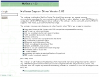 The multiuser/multitasking BayCom Packet Terminal Driver program is a general purpose communications package for communicating with a BayCom modem attached to your IBM-PC/clone in conjunction with the TFPCX Baycom driver software. The software will also work with a normal TNC if it supports KISS mode, such as the Kantronics range.
 -
 The ZS6BKW multiband antenna, an optimized variant of the classic G5RV, features a 102-foot (31.1 m) horizontal span and a 39.1-foot ladder line matching section. This design, derived by G0GSF (formerly ZS6BKW) in the early 1980s using computer programs and _Smith charts_, aims for improved SWR across multiple HF bands compared to its predecessor. Construction details specify Wireman 554 ladder line and #14 AWG THHN copper wire for the radiators, with precise instructions for determining the velocity factor (VF) of the ladder line using an antenna analyzer or dip meter, ensuring accurate physical length for the matching section. The radiator length is electrically 1.35 wavelengths for the 20-meter band, requiring careful trimming during tuning. Field measurements with an _AIM-4170C_ analyzer by KI4PMI and NC4FB demonstrated good SWR curves and bandwidth on 6, 10, 12, 17, 20, and 40 meters. The antenna was deemed unusable on 15 and 30 meters due to very high SWR, but an LDG AT-100PRO autotuner successfully brought 6 and 80 meters into tune. Contacts were made on 80, 40, 20, and 17 meters, including a **17-meter** contact to Spain. EZNEC models for 80-6 meters are provided, along with an AutoEZ model by AC6LA, which predicted good SWR for 80-10 meters. W5DXP's modifications for an all-band HF ZS6BKW are also referenced.
 -
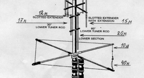 Picture taken from official manual with notes on tuning stubs for each band
 -
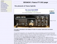 Relay substitution tutorial, power amplifier tuning and Technical Characteristics
 -
 A 102-inch vertical whip, commonly a CB antenna, forms the core of this low-profile 10-meter antenna design, optimized for the 28 MHz band. The construction details specify three 8-foot radials made from scrap wire, connected to a common point. This simple yet effective setup is designed for ease of construction and deployment, making it accessible for operators with limited space or materials. The design emphasizes using readily available components, including PVC pipe for the mast and a SO-239 connector for the feedline, ensuring a straightforward build process for a resonant quarter-wave vertical. Field results indicate that this antenna provides good performance for local and DX contacts on 10 meters, despite its compact footprint. The author, N8WRL, shares practical insights into its construction and tuning, highlighting its suitability for temporary or permanent installations where a full-sized antenna might be impractical. Comparisons to more complex designs suggest that this low-profile vertical offers a respectable signal-to-noise ratio and effective radiated power for its size, proving that simple designs can yield satisfying on-air results.
 -
 Airband Frequencies collection in french PDF files by SWL FE10262
 -
 Reviews of the popular portable HF transceiver by Elecraft
 -
 Low Country Amateur Radio Club Summerville, South Carolina 147.060+ / 147.030
 -
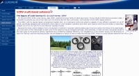
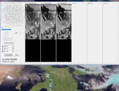 A portable decoder for METEOR M weather satellite LRPT signal, available for windows and Linux
 -
 Constructing a high-performance RF spectrum analyzer up to 1000 MHz requires careful attention to component selection, shielding, and circuit isolation. This resource details a project that improves upon the _Spectrum Analyzer for the Radio Amateur_ design by Wes Hayward (W7ZOI) and Terry White (K7TAU), incorporating ideas from Scotty Sprowls' project, particularly his 1013.3 MHz IF bandpass cavity filter. The analyzer utilizes a Mini-Circuits SRA-11 mixer with a sweeping local oscillator from 1013 to 2013 MHz, feeding into a 4-pole copper pipe cavity filter. The design employs a second SRA-11 mixer with a fixed 1024 MHz LO to produce a 10.7 MHz final IF. This signal then passes through narrowband resolution filters and is processed by Analog Devices AD603 and AD8307 ICs for IF amplification and logarithmic detection, driving an oscilloscope in X/Y mode. The project emphasizes modular construction, using salvaged components and double-sided FR4 material for PCBs, with critical notes on minimizing spurious images through effective shielding and proper voltage regulation for each module. Key components include a Z-Communications V585ME48 VCO for the first LO and a Z-Comm V583ME01 VCO controlled by a Motorola MC145151 PLL for the second LO. An optional Hittite HMC307 step attenuator and K&L 5L121-1000/T5000-O/O low-pass filter manage RF input. Tuning procedures for the 10.7 MHz IF resolution filter are also detailed, showing before-and-after spectrum views.
 -
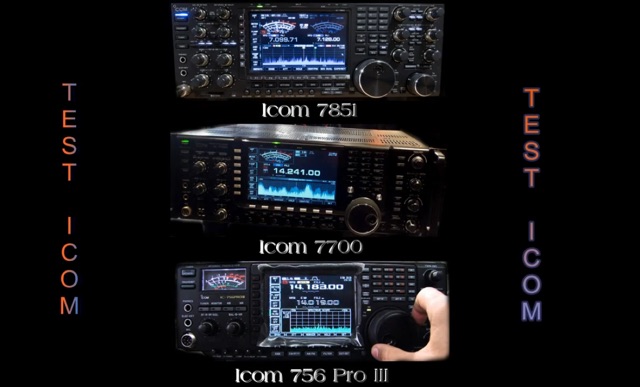 Reception test comparison between IC 756 pro III, IC 7700 and the last jewel by ICOM IC 7851
 -
 The 1/4 wavelength vertical antenna project, initially designed for 20 meters, has evolved into a versatile portable solution covering 10 through 60 meters. K0BXB details its construction, emphasizing a bottom-loaded design with a tapped loading coil and four 10-foot counterpoise wires. The author shares personal experiences and field results, including **18 QSOs** during a park activation on 17m and 30m with 10 watts, and a **2,435-mile** contact with a contest station in Bonaire on 20m using 5 watts. Comparisons are drawn to commercial offerings like the _Wolf River Coils TIA_ and _QRPGuys Triband Vertical_, highlighting the DIY antenna's small footprint, light weight, and ease of tuning for POTA activations. The resource includes insights into using test equipment such as the _NanoVNA_ for SWR optimization and discusses various radiator lengths, from 17-foot wire to a 102-inch whip, demonstrating adaptability for different portable setups. Construction tips cover coil winding, tap placement, and connecting feedlines and radials using common components.
 -
 The Big Gun's Guide" is a comprehensive exploration of low-band propagation, aimed at serious Amateur Radio operators. It delves into the complex physics of the ionosphere at lower frequencies, contrasting it with HF propagation. The book covers essential topics like ionospheric fundamentals, propagation mechanisms, magneto-ionic effects, and disturbances. It also addresses the challenges of low-band DXing and provides insights for overcoming them. Brown's work is detailed and technical, offering valuable knowledge for those seeking to master the intricacies of low-band communication
 -
 Assessing the ICOM IC-R9000 communications receiver, this review details its operational parameters and user experience for radio enthusiasts. Introduced in 1985, the IC-R9000 covers a broad frequency spectrum from 0.1 MHz to 1999.8 MHz, making it suitable for a wide array of listening activities from medium wave (MW) to VHF/UHF. Key performance metrics include a dynamic range of **102 dB** with the narrow SSB filter, crucial for discerning weak signals in crowded bands, and its substantial physical dimensions of 424 x 150 x 365 mm and 20 kg weight. The receiver's architecture supports various modes, though it notably lacks synchronous detection, a feature often desired for improved AM reception under fading conditions. It incorporates 1000 memory channels and robust scanning capabilities, facilitating efficient monitoring across its extensive frequency range. This analysis provides insights into the IC-R9000's capabilities and limitations, offering a historical perspective on a significant piece of amateur radio and shortwave listening hardware.