Search results
Query: 24 MHz
Links: 72 | Categories: 0
-
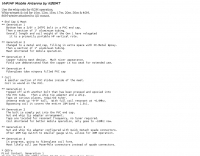
 A 9 dB gain 70cm collinear antenna construction is detailed, utilizing eight half-wavelength sections of _RG58/U_ coaxial cable. The design incorporates specific calculations for velocity factor (0.66 for RG58/U) to determine precise element lengths, such as 223mm for a half-wavelength at 444 MHz. A quarter-wave radiating element of #16 solid wire, 169mm long, is added to the top, and a 160mm aluminum tube acts as a quarter-wave counterpoise at the feed point. RF choke baluns, constructed from three _FT50-43_ toroids, are positioned a half-wavelength from the feed point to mitigate common mode current. Assembly involves soldering the coax sections in series, followed by SWR testing during construction and final mounting within a ¾-inch PVC pipe. The article suggests using four half-wave elements for a shorter antenna, noting a potential slight increase in SWR, which can be mitigated with quarter-wave ground radials. The design principles and formulas are scalable for other VHF/UHF bands like 6m, 2m, or 1¼m, providing a versatile homebrew solution for enhanced gain.
 -
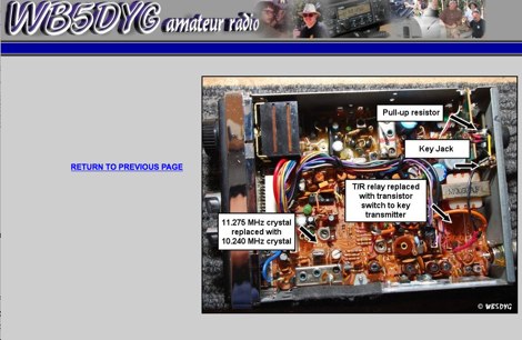
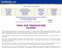 Circuit diagram and discription of 7 MHz Ham Radio SSB Transceiver. Transceiver using two MC1496, 4.43 MHz Ladder filter, LM386, LM324 and IRF840 in final.
 -
 A self-supporting vertical antenna design for stationary-mobile HF-VHF operation is presented, emphasizing ease of construction with common materials like a fiberglass fishing rod and PVC pipe. The design focuses on creating a set of no-tuner monoband radiators for bands such as **2m**, **6m**, 10m, and 12m, with an overall radiator support length of 3.3m. The construction process details the assembly of the antenna base using a magnetic mount, PL-259 connector, and PVC pipe sections, which then supports the telescopic fishing rod. Radiator extensions are cut to achieve quarter-wave resonance on specific bands, with detailed instructions for 6m (50-51 MHz), 10m (28.5 MHz), and 12m (24.9 MHz). For lower HF bands like 15m, 17m, and 20m, the design incorporates base-loading coils, with specific turn counts provided (e.g., 21 turns for 20m). The project also suggests using an _antenna analyzer_ for precise tuning of extensions and coils, moving beyond theoretical values to achieve optimal performance. The author, _IK1ZYW_, notes that for 80m and 160m, the antenna becomes less efficient as a vertical, suggesting alternative configurations like an inverted-V dipole or asymmetrical inverted-L.
 -
 A detailed drawing of a VHF UHF Log periodic antenna by VA2PHI
 -
 The multi-band trapped dipole is resonant on approx 3.7, 7, 14, 24 7 28.5 Mhz. The overall top length needs to be approximately 32.9 Meters
 -
 This antenna is easy to build and suitable for broadband work, satellite work and terrestrial work.
 -
 The NCDXF/IARU International Beacon Project schedule provides precise transmission start times for 18 beacons operating on 14.100 MHz, 18.110 MHz, 21.150 MHz, 24.930 MHz, and 28.200 MHz. Each beacon transmits every three minutes, cycling through its callsign at 22 WPM followed by four one-second dashes. The initial callsign and first dash are sent at 100 watts, with subsequent dashes at 10 watts, 1 watt, and 100 milliwatts, enabling **propagation analysis** across varying signal strengths. The schedule lists the minute and second within each hour for the first transmission of each beacon on its respective frequencies. This resource allows **DXers** and **contesters** to accurately predict beacon transmissions for real-time propagation assessment. For example, 4U1UN transmits first at 00:00 on 14.100 MHz, followed by VE8AT at 00:10, and W6WX at 00:20, continuing the sequence. The page also notes recent hardware upgrades, such as the installation of IBP 2.0 controllers with Icom 7200 radios at some sites, and provides status updates for beacons experiencing hardware failures or those not recently heard, aiding in troubleshooting and managing expectations for monitoring.
 -
 Demonstrates the construction and performance of an updated ZS6BKW multiband dipole, a variant of the _G5RV_ antenna, specifically designed for HF operation. The article details a real-world installation using 13.5m copper wire elements and 12.2m of 450 Ohm ladder line, configured as a sloping inverted-V with the apex at 10m and ends at 4m above ground. It covers the critical aspect of impedance matching, incorporating an 8-turn choke balun at the feedline transition to RG-58U coax to mitigate RF common mode current. Measurements confirm favorable SWR readings below **1.3:1** on 7.1 MHz, 14.11 MHz, 18.06 MHz, and 24.8 MHz, indicating effective resonance across 40m, 20m, 17m, and 12m bands. The installation also shows usable SWR dips on 3.55 MHz (5:1), 29.02 MHz (2:1), and 50.84 MHz (3:1), extending its utility to 80m, 10m, and 6m with an antenna tuning unit. Initial on-air results report clear reception of stations over **5000km** away, validating its DX potential.
 -
 The K5OE 2-meter vertical mobile antenna design, detailed in this resource, employs a 3/8-wavelength vertical section complemented by four shortened radials, forming an off-center-fed vertical dipole. This configuration creates a self-contained lower half, enhancing efficiency compared to traditional 1/4-wave monopoles relying on vehicle bodies for a ground plane. The article specifies construction using PVC components, 10-gauge insulated wire for elements, and provides precise dimensions in both inches and centimeters for the 25-3/16" (64 cm) vertical and 7-3/16" (20 cm) radials. Performance data indicates an honest 3 dBi of gain at 6 feet elevation (2 dBi free-space), with a pattern favoring the horizon, suitable for Low Earth Orbit (LEO) satellite communications. At 20 feet high, the same antenna exhibits almost 6 dBi of gain, with a nominal 50 Ohm feedpoint impedance at 146.850 MHz. Tuning instructions involve trimming element lengths, with the author achieving a 1.2:1 SWR by pruning the mast to 24-3/4" and radials to 7". The resource highlights the antenna's effectiveness for mobile LEO satellite uplinks, particularly at low elevations, and its suitability for fixed, mobile, or portable operations. The flexible wire elements allow for easy folding, making it a practical choice for backpacking. The original design by K5OE was previously hosted on aol.com.
 -
 PA3FWM's software defined radio (SDR) page documents his extensive hardware and software development efforts between 2004 and 2009. Initial experiments utilized a direct conversion receiver with 90-degree phase difference, feeding a PC soundcard at 48 kHz sample rate, covering 24 kHz of spectrum around a 7080.5 kHz local oscillator. This setup, similar to AC50G's QEX 2002 article, allowed for basic I/Q signal processing to distinguish signals above and below the LO frequency. Limitations included fixed crystal frequencies, 16-bit dynamic range, and narrow bandwidth. Subsequent hardware iterations aimed for enhanced performance, incorporating external 24-bit ADCs with 192 kHz sample rates, connected via 10 Mbit/s Ethernet. A **MC145170-based PLL** and programmable octave divider provided a 58 kHz to 30 MHz tuning range. The **Tayloe mixer** was employed, with differential outputs feeding a PCM1804 ADC. An ATmega32 microcontroller handled serial data conversion to Ethernet frames, though without CRC calculation due to processing constraints. Later designs integrated AD7760 2.5 Msamples/second ADCs and a Xilinx Spartan-3 FPGA, enabling direct reception of 0-1 MHz spectrum and eventually 2.5 MHz bandwidth across the shortwave spectrum. Software was refactored to use an initial 8192 non-windowed FFT for efficient high-bandwidth processing. The project culminated in a two-way QSO on 21 MHz using the developed hardware and software, demonstrating transmit capabilities with a D/A converter. The system exhibited a 2.5 MHz wide spectrum display and a zoomed 19 kHz display, capturing signals like ionospheric chirp sounders and RTTY contest activity. Challenges included noise leakage from digital circuitry and cooling for high-power dissipation components.
 -
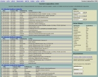 Catalogs over 9,300 radio transmissions heard within Finland, providing a detailed frequency database for Finnish radio enthusiasts. The resource lists frequencies for various services, including maritime VHF channel 16 at **156.800 MHz**, RHA68 channel 16 at 71.100 MHz, and _MIL AIR_ frequencies like 251.100 MHz. It also documents air traffic control frequencies, such as 123.775 MHz for Area Control and 127.000 MHz for Approach Control, alongside frequencies for Finnish Air Force operations at 140.550 MHz. The database includes entries for commercial shared channels at 170.450 MHz and 458.250 MHz, as well as specific local business frequencies like 443.125 MHz for Sale Merimasku. Shortwave broadcast entries are also present, noting stations like BBC at 6.035 MHz from Tashkent and AIR Akashvani Ext.Sce at 11.900 MHz from Bangalore. The site organizes its extensive listings by categories such as "Liikenne" (Traffic) with 2397 entries, "Radioamatoori" (Amateur Radio) with 781 entries, and "Yle" (General) with 2305 entries. The database was last updated on 26.2.2024, reflecting ongoing maintenance and additions to its comprehensive collection of Finnish radio spectrum data.
 -
 A multiband end-fed antenna that cover 3.5 to 30 Mhz using a 1:64 Balun based on a FT240-43 core
 -
 The article "Exploring the World of 10 Meter Beacons" by Ken Reitz, KS4ZR, provides an in-depth look at 10-meter beacon operations, focusing on their utility for propagation analysis. It details FCC Rules part 97.203 governing beacon stations, including license requirements, power limits (under 100 watts), and the specified band segment of 28.200-28.300 MHz for U.S. operations. The content highlights the diversity in beacon construction, from converted CB radios to home-brew QRP transmitters, and discusses the robust operating conditions these 24/7 stations endure. The resource presents several case studies of active 10-meter beacon operators like Ron Anderson KA0PSE/B, Domenic Bianco KC9GNK/B, and Bill Hays WJ5O/B, detailing their equipment, antenna setups, and typical signal report volumes. It also introduces the NCDXF/IARU International Beacon Project, which features 18 synchronized beacons worldwide transmitting on 28.200 MHz at varying power levels (100W, 10W, 1W, 100mW) to facilitate propagation testing. The article also covers the PropNet Project utilizing PSK31 on 28.131 MHz and the 250 Synchronized Propagation Beacon Project on 28.250 MHz. Practical advice for monitoring includes using the RST reporting method, understanding the impact of the solar cycle on 10-meter propagation, and tips for setting up a personal beacon, such as frequency selection and power output considerations. The IY4M Guglielmo Marconi Memorial Beacon Robot on 28.195 MHz is also mentioned for its automatic QSO mode. The article concludes with a list of other resources for 10-meter beacon information.
 -
 This resource details the computer-optimized design of the _ZS6BKW_ multiband dipole, an evolution of the classic _G5RV_ antenna. It begins by referencing the original 1958 RSGB Bulletin article by Louis Varney G5RV, explaining the operational principles of the G5RV's flat-top and open-wire feedline on 20m and 40m, noting its impedance transformation characteristics for valve amplifiers of that era. The article then transitions to the rationale for optimizing the design for contemporary solid-state transceivers requiring a 50 Ohm match. The core of the project involves using computer modeling to determine optimal lengths for the flat-top and matching section, aiming for a VSWR of less than 2:1 on multiple HF bands. It discusses the process of calculating feedpoint impedance based on antenna length and frequency, referencing professional literature from Professor R.W.P. King at Harvard University. The analysis also considers the characteristic impedance (Z(O)) of the open-wire line, identifying a broad peak of adequate values between 275 and 400 Ohms. Specific design parameters for the improved ZS6BKW are presented, including a shorter flat-top and a longer matching section compared to the original G5RV, with a velocity factor of 0.85 for the 300 Ohm tape. The article confirms acceptable matches on 7, 14, 18, 24, and 28 MHz bands when erected horizontally at 13m, and also discusses performance in an inverted-V configuration, noting frequency shifts. The author, Brian Austin ZS6BKW, emphasizes the antenna's suitability for modern 50 Ohm coaxial cable without a balun.
 -
 Demonstrates the iterative design and construction of a **tapped HF/VHF mobile vertical antenna** by K0EMT, detailing four generations of development. The antenna supports operation on 80m, 40m, 30m, 20m, 17m, 15m, 12m, 10m, 6m, and 2m bands. Initial designs, like Generation 1, featured a 3/8" x 24TPI bolt in a PVC end cap with a 1" aluminum tubing mast, resulting in a 9'9" overall length and resonance around 6.9 MHz with the full coil. Subsequent generations refined the mast and coil forms, transitioning from aluminum to copper tubing (Generation 3, found too weak) and eventually fiberglass for the coil form (Generation 4, in progress). Coil tapping points were adjusted to achieve resonance without an external tuner in Generation 2. The project outlines material costs, totaling approximately $25, and mentions a successful 28 MHz QSO with EA3XA using an ICOM IC-706 mk II at 100 Watts. For 80m operation, an external wire with the maximum coil setting is used, or a 56" extender below the coil for stationary use.
 -
 The Grid Yagi (or Grid Quad) is a high performance yagi antenna that can be built with readily obtainable inexpensive materials. Described here is a 6 element 2 meter version with a boom length of about 1 wavelength, shown
 -
 The Deutscher Amateur-Radio-Club (DARC) e.V. serves as the largest association for radio amateurs in Germany and Europe, structured into 24 districts and approximately 960 local chapters nationwide. Its core mission involves fostering amateur radio and establishing favorable conditions for the Amateur Radio Service. The DARC actively participates in international affairs as a member of the **International Amateur Radio Union (IARU)**, ensuring German interests are represented on a global scale. Recent activities include the announcement of the FUNK.TAG in Kassel for April 25, 2026, and the HAMCamp at **HAM RADIO** in Friedrichshafen from June 26-28, 2026, offering discounted participation for young operators up to 27 years old. The club also supports special events, such as a short-term award and special callsign DB15ØWG to commemorate the 150th anniversary of the Weimar–Gera railway line, active from April 1 to June 30. Regular updates, like the Deutschland-Rundspruch 11/2026, cover topics from the status of 70 MHz band permissions to satellite deployments like Ten-Koh 2, and contest results such as the WWA YL event. Propagation forecasts, including Kp indices and solar flux values, are provided by Hartmut Büttig, DL1VDL, offering insights into HF conditions and Gray-Line DX opportunities. The DARC also reports on district elections and space-related events like the Bochumer Weltraumtag, highlighting the diverse engagement of its members.
 -
 Operational testing of a 10.07-meter portable HF vertical antenna, constructed from telescoping aluminum tubing (36, 32, 22, 17 mm diameters), yielded SWR measurements below 1.5 across multiple bands. Initial trials on 14.150 MHz showed an SWR of 1.6, while 7.075 MHz was problematic. Subsequent adjustments, including a 13 cm extension to the radiating element, improved performance, enabling operation on 6, 15, and 40 meters without a balun, and adding 12 meters with a balun. The design prioritizes portability, allowing transport in a standard vehicle and single-person deployment. Four 10.07-meter radials are connected at the base to enhance ground plane effectiveness. The article details the mechanical assembly, including custom adapters for tube transitions and a PVC sanitary tube sleeve for base insulation, ensuring robust field deployment. Final SWR measurements, documented with an _MFJ-259_ antenna analyzer, confirm operational ranges: 6.800-7.500 MHz (SWR < 1.5), 20.800-22.500 MHz (SWR < 1.5), and 48.800-51.500 MHz (SWR < 1.5) without a balun. With a balun, the antenna achieved SWR < 1.5 on 13.750-15.000 MHz and 24.890-28.350 MHz, demonstrating its versatility for portable _DXpeditions_.
 -
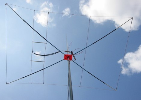
 G3TPW CobWebb Antenna for the 14, 18, 21, 24 and 28 MHz Bands
 -
 Demonstrates the design and construction of a compact, portable multi-band mini-delta loop antenna, specifically optimized for /P (portable) operations from remote locations like Scottish islands. The resource covers the theoretical underpinnings of half-wave loops, contrasting closed and open configurations, and then details the application of a folded dipole principle to achieve a 50-ohm match for direct coax feed. It presents empirical formulas for calculating element lengths, considering the velocity factor of common wire types, and provides a detailed example for a 20m (14.175 MHz) version. The article includes a comprehensive table of dimensions and allowances for a five-band (20m, 17m, 15m, 12m, 10m) mini-delta beam, along with construction hints for the central support and balun. It specifies a 1:1 trifilar balun wound on a ferrite rod and describes the antenna adjustment process using an _MFJ-259B Antenna Analyser_. Initial test results indicate an SWR of 1:1 at resonance and a bandwidth of approximately 240 kHz on 20m, even at a low height of five feet above ground. The distinctive utility lies in its focus on a practical, easily deployable beam antenna for portable DXing, offering a viable alternative to more complex or larger arrays.
 -
 DK7ZB provides detailed construction plans for Moxon antennas utilizing tapered aluminum tubing, specifically outlining dimensions for 50 MHz, 28 MHz, 24 MHz, and 21 MHz bands. The resource emphasizes maintaining specific taper lengths for optimal performance and describes a tuning method involving symmetrical element shifts. It also addresses stacking considerations, noting that two Moxons can be stacked 1m apart with a 90° rotation to avoid severe detuning, unlike co-planar mounting. Performance figures for the 50-MHz Moxon include a gain of **4.1 dBd** and a front-to-back ratio of _30 dB_. The construction utilizes copper fittings for element connections, with a recommendation to varnish edges against corrosion. The page features images of built antennas by _DK8UH_ and VK2QO, illustrating practical implementations for the 6-meter and 10-meter bands, respectively.
 -
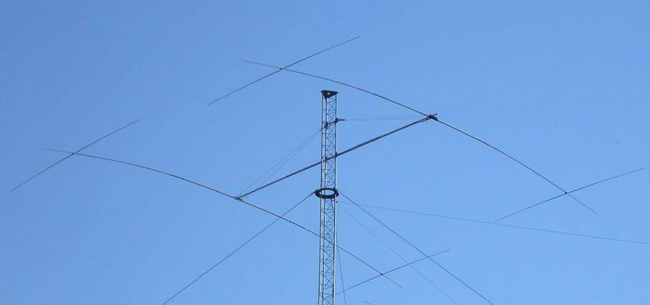
 Homebrew a cobwebb antenna for the HF bands. This page describe a cobwebb multiband antenna resonating on 14 18 21 24 and 28 MHz. The cobweb antenna model can be considered a fan dipole, or better, multiple dipoles fed in parallel.
 -
 Design for a 5 element 2 Metre beam with a forward gain of 8dBD and a front to back ratio of over 24dB.
 -
 Building an omnidirectionnal antenna for the 23 cm band, 1240 - 1270 Mhz
 -
 The NCDXF/IARU International Beacon Project operates a worldwide network of 18 high-frequency radio beacons, continuously transmitting on 14.100, 18.110, 21.150, 24.930, and 28.200 MHz. These beacons, initially launched in 1979 with a single station and expanded to the current 18-beacon system in 1995, provide reliable signals for both amateur and commercial users to assess current **ionospheric propagation** conditions. The system's design, construction, and operation are managed by volunteers, covering hardware and shipping costs. The resource details the evolution of the beacon network, including the transition from Kenwood TS-50s transmitters to Icom IC-7200 radios with a new controller design implemented in 2015. It explains how listening for these 100-watt signals, transmitted to vertical antennas, allows operators to determine band openings and optimal propagation paths globally. The content also references three QST articles providing historical context and technical specifics of the beacon project. Practical information includes methods for identifying transmitting beacons via a schedule or specialized software like FAROS and Skimmer, which integrates with the **Reverse Beacon Network** for automated monitoring.
 -
 The _Italian VHF Beacons_ resource provides a detailed listing of active and QRT amateur radio beacons operating across VHF, UHF, and SHF bands within Italy. Each entry specifies the beacon's callsign (e.g., IQ1SP/B), operating frequency (e.g., 144.411 MHz), QTH locator (e.g., JN44VC), effective radiated power (ERP) in watts, and antenna configuration (e.g., Big Wheel, 4x Dipole, Yagi). This data is crucial for radio amateurs involved in propagation studies, equipment testing, and long-distance (DX) communication on these higher frequency bands, offering fixed signal sources for monitoring. This compilation, last updated in October 2005, serves as a historical snapshot of Italian beacon activity. For instance, it lists several 144 MHz beacons with ERPs ranging from **0.1W** to **10W**, and higher frequency beacons such as I8EMG/B on 1296.880 MHz and I3EME/B on 24192.132 MHz. The inclusion of QRT (Quiet Radio Teletype) status for many entries indicates the dynamic nature of beacon operations over time. Users can utilize this information to identify potential signal sources for band openings or to calibrate their receiving equipment against known transmissions.
 -
 Article describing how to homebrew a yagi antenna for 50 MHz, includes plans for a four and five elements yagi beam and details how how match impedence with a gamma match
 -
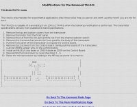 TM-241A RX/TX mods The TM-421 a is capable of transmitting from 136 to 174 MHz when the following modification is performed
 -
 The Northern Ohio DX Association (NODXA) operates a voice repeater on 147.36 MHz with a +600 kHz shift, utilizing the club callsign W8DXA. The organization provides an award program for contacting its members and offers DXCC and Honor Roll patches to recognize member achievements. NODXA publishes a monthly newsletter containing DX information and meeting minutes, with a recent brochure and membership application dated May 2024. The club actively promotes DXing, allocating a portion of its finances to support DXpeditions, and several members have also financed their own expeditions. The NODXA roster was last updated in June 2015, and a list of supported DXpeditions was revised in June 2024. Tedd Mirgliotta, KB8NW, serves as the club president and is the editor of the OPDX Bulletin, a widely distributed internet and packet cluster resource. Meetings are held on the first Monday of each month at Amici Italian Restaurant & Bar in North Royalton, Ohio, located at 13000 Royalton Road, near the intersection of Route 82 and W.130th Street. The club leadership includes Dennis Stuber, K8LBT, as Vice President; Glenn Williams, AF8C, as Secretary; and Mary Michaelis, N8DMM, as Treasurer.
 -
 Over 100 amateur radio beacon audio files are presented, offering a direct auditory experience of propagation conditions across a wide spectrum of frequencies, from 1.8 MHz to 47 GHz. These recordings, primarily captured by IW3FZQ and IK3NWX, document signals from beacons such as DK0WCY, IY4M, GB3RAL, and S55ZRS, providing a valuable resource for **propagation study** and **beacon monitoring**. Each entry in the list specifies the beacon's callsign, its operating frequency in kHz, and the recording operator. This compilation includes signals from beacons located in various grid squares like JN55VF, JO44VQ, and IO91IN, illustrating diverse geographical origins. The frequencies covered span the 160m, 80m, 40m, 30m, 20m, 17m, 15m, 12m, 10m, 6m, 4m, 2m, 70cm, 23cm, 6cm, 3cm, 1.2cm, and 6mm amateur bands. Users can listen to these recordings to identify characteristic beacon tones and observe signal strength variations. The resource also invites other radio amateurs to contribute their own beacon audio files, fostering a collaborative archive of propagation data. The last update to this collection was on March 24, 2009, indicating a historical snapshot of beacon activity. Accessing the files requires the Real Player software.
 -
-
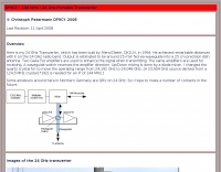
 Pictures and design plan of a 28 MHz - 70 MHz transverter 3Watts in - 8Watts out by 9A2SB
 -
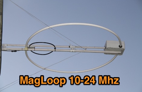 A few pictures of an homebrew magnetic loop RTX antenna project, working from 30 to 12 meters with excellent results
 -
 The W6NL Moxon Yagi is a high-efficiency two-element 40m Yagi that uses cross elements to provide both loading and Moxon coupling, addressing the challenge of deploying a directional antenna on the 40-meter band. This resource details the transformation of a _Cushcraft XM240_ Yagi into this Moxon configuration, replacing the original loading coil LCA sections with four new assemblies. The guide provides comprehensive instructions for building the boom and elements, including specific dimensions for new sections and tee loading elements, along with detailed drawings and a full parts list for the conversion. Performance data indicates the converted antenna achieves **10.73 dBi** gain at 7.050 MHz with 99.5% efficiency and a high front-to-back ratio. The VSWR bandwidth is over **300 kHz**, ensuring good performance across a significant portion of the 40m band. Construction involves reinforcing element sections, attaching tee loading elements with U-bolts, and implementing element guying using materials like _Phillystran_ to manage sag and maintain structural integrity.
 -
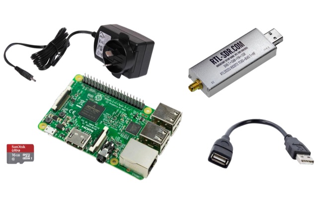 This project is a Software Defined Radio Receiver. It has a frequency range of 24MHz 1.2GHz. It can demodulate AM, FM, USB, LSB with selectable bandwidths of 600, 2400, 2800, 3200 and 6400Hz. Using a simple RTL-SDR Dongle and Raspberry Pi 3 computer using GNU RADIO
 -
 Documents the construction of a **VHF/UHF** antenna addition for the Buddipole HF antenna system, leveraging the existing Versa-Tee component. The project details the fabrication of a custom antenna mount from angle aluminum, including specific drilling and tapping for 3/16"-24 bolts, and the creation of radials from Simpson Strong Tie Insulation Supports. It specifies radial lengths for 70 centimeters (6 inches from the center stud) and 2 meters (19 1/4 inches), noting the use of wire nuts for safety. The resource outlines the construction of a mast from 1/2" ID PVC conduit, connected with 3/8"-24 connecting nuts and bolts, mirroring the Buddipole's modular design. It describes the integration of a mobile dual-band antenna with a 3/8"-24 mounting stud and the custom coax setup with BNC and **PL-259** connectors. Field testing with an FT-817ND and a separate dual-band SWR meter confirmed good SWR on both 2 meters and the 440-450 MHz section of 70 centimeters, with positive reception reports during Field Day activities. Further, the article describes the creation of a custom carrying solution, including a 22-inch tripod bag and a fabric roll-up, to emulate the portability of the original Buddipole system.
 -
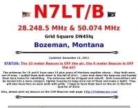 Operating 28.249 MHz and 50.074 MHz from Bozeman, Montana
 -
 PS8RF beacon tx in 7.035 Mhz with 3 W
 -
 Constructing a high-performance RF spectrum analyzer up to 1000 MHz requires careful attention to component selection, shielding, and circuit isolation. This resource details a project that improves upon the _Spectrum Analyzer for the Radio Amateur_ design by Wes Hayward (W7ZOI) and Terry White (K7TAU), incorporating ideas from Scotty Sprowls' project, particularly his 1013.3 MHz IF bandpass cavity filter. The analyzer utilizes a Mini-Circuits SRA-11 mixer with a sweeping local oscillator from 1013 to 2013 MHz, feeding into a 4-pole copper pipe cavity filter. The design employs a second SRA-11 mixer with a fixed 1024 MHz LO to produce a 10.7 MHz final IF. This signal then passes through narrowband resolution filters and is processed by Analog Devices AD603 and AD8307 ICs for IF amplification and logarithmic detection, driving an oscilloscope in X/Y mode. The project emphasizes modular construction, using salvaged components and double-sided FR4 material for PCBs, with critical notes on minimizing spurious images through effective shielding and proper voltage regulation for each module. Key components include a Z-Communications V585ME48 VCO for the first LO and a Z-Comm V583ME01 VCO controlled by a Motorola MC145151 PLL for the second LO. An optional Hittite HMC307 step attenuator and K&L 5L121-1000/T5000-O/O low-pass filter manage RF input. Tuning procedures for the 10.7 MHz IF resolution filter are also detailed, showing before-and-after spectrum views.
 -
 Presents a historical timeline of amateur radio satellites, beginning with the inaugural _OSCAR 1_ in 1961 and extending through ARISSat-1 in 2011. It outlines the evolution of these orbiting transponders, initially simple battery-operated beacons, into sophisticated platforms supporting educational initiatives, emergency communications, and technology demonstrations. The document highlights the significant contributions of various AMSAT organizations and other entities in developing and deploying these spacecraft. Each entry provides specific launch details, including the date, launch vehicle, and initial orbital parameters such as apogee, perigee, and inclination. For instance, AMSAT-OSCAR 7 (AO-7) launched in 1974 into a 1459.00 x 1440.00 Km orbit, while AMSAT-OSCAR 40 (AO-40) achieved a highly elliptical 58665.00 x 1157.00 Km orbit. The resource also notes the allocated amateur satellite service frequencies, including 29 MHz (10m), 145 MHz (2m), 435 MHz (70cm), 1270 MHz (24cm), and 2400 MHz (13cm). The compilation serves as a concise reference for understanding the progression of amateur satellite technology and operations over five decades, showcasing the collaborative efforts of the global amateur radio community in space communication endeavors. It details the physical characteristics and project affiliations for many of the **20** satellites listed, providing a foundational historical context.
 -
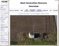 The world's oldest beacon OZ7IGY in JO55WM 28 MHz to 24 GHz.
 -
 The Boone Area Radio Klub (BARK) serves Boone County, Iowa, as its local amateur radio club, actively welcoming visitors to its meetings and weekly ARES nets. The club maintains a 2-meter repeater on 146.850/250 MHz with a 114.8 Hz tone and a 440 MHz repeater on 443.9+ MHz, both situated at the Boone County Hospital, with a simplex fallback on 146.550 MHz for the 2-meter net. Additionally, BARK supports the Iowa 160-meter ARES net at 1.972.5 MHz, which operates at 9:30 PM on Sundays, featuring a rotating schedule of net controls including KNØR, KBØMPL, NØISU, KEØQEU, and KBØLPI. BARK conducts bimonthly license testing sessions on the second Saturday of even-numbered months, with specific dates like October 19, 2024, at the Hamboree, requiring a $15 fee and prior FCC Registration Number (FRN) acquisition. The club's activities are well-documented through numerous photo galleries from past Field Days (1998, 1999, 2008, 2010, 2013, 2017, 2018, 2019), JOTA events (2013), and special event stations (2010 B&SVRR&M). Members like KBØMPL (Margot Conard) have contributed educational PowerPoint presentations on topics such as "Fun with Handie Talkies," "HF Propagation," and "Digital Mode - FLDIGI - OLIVIA 8/500 - JT65 HF - BAND PLANS." The club's officers, as of May 2018, include WØFS (Clay Conard) as President, NØISU (Mitch Carroll) as Vice-President, and KBØLPI (Eric Sloan) as Treasurer/Secretary, guiding the club's operations and community engagement.
 -
 Details the Highline Amateur Radio Club (HARC), an organization dedicated to public service through Amateur Radio and community engagement for radio enthusiasts. The club conducts a monthly general meeting on the 4th Saturday at 10 AM at Burien Fire Station 28. HARC also hosts a weekly net on Tuesdays at 7:30 PM, operating on **146.660 MHz** with a -600 kHz offset and a 103.5 Hz **CTCSS tone**. Additionally, members gather for a weekly breakfast on Fridays at 9:30 AM at Tuscany at Des Moines Creek. The resource provides current weather conditions for Burien, WA, displaying temperature, wind chill, and a three-day forecast from the National Weather Service Seattle/Tacoma Office. It also links to the latest ARRL Newsletter, noting a system breach in May 2024 affecting archived links. The club's activities include regular meetings, on-air nets, and social gatherings, supporting local amateur radio operations and community involvement.
 -
 The ZS1J/B beacon operates on 28.2025 MHz with 5 Watts output to a half-wave, end-fed vertical antenna, initially installed in 1977 as ZS5VHF near Durban. The 10-meter transmitter is a modified 23-channel CB radio, and the identification keyer uses a diode matrix unit with TTL ICs from the same era. After relocation to Plettenberg Bay in 1993, the beacon has been in continuous service, with additional QRP transmitters later installed for other bands. In 1994, a single-transistor, 80-meter, 0.5-watt QRP transmitter with a half-wave dipole was added on 3586 kHz, followed by a 160-meter, 0.5-watt unit on 1817 kHz. A 30-meter, 0.5-watt transmitter was installed in 1996, operating on 10.124 MHz. In 2002, a 40-meter QRRP beacon on 7029 kHz, with an output of 100 microwatts, achieved DX reports up to 1100 km from ZS6UT in Pretoria. Best DX reports for the 80m and 160m beacons came from 9J2BO.
 -
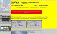 Two beacons in 3 and 1.2 cm band, 10368.755 MHz and 24048.870 MHz
 -
 AC7GZ/B is a converted Sharp CB-2460 Citizens Band transceiver operatin on 28.2118 MHz.
 -
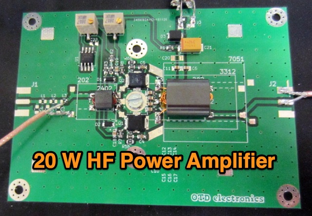 A HF power amplifier with a push-pull of AFT09MS015N. The (small-signal) gain of the amplifier is around 26 dB in the lower HF band and goes down to about 24 dB on the higher end and still around 21 dB at 50 MHz. Its input matching is relatively good at the lower HF and degrades above 10 MHz.
 -
 The Burlington Amateur Radio Club (BARC) provides a community hub for amateur radio operators in Burlington, Ontario, Canada, offering regular meetings, educational programs, and a dedicated hackspace for electronics and radio experimentation. The club operates several repeaters, including a 2m repeater (VE3RSB) on 147.210 MHz with a +600 kHz offset and 131.8 Hz tone, which supports AllStar node 542490. Additionally, BARC maintains a UHF repeater on 444.825 MHz with a +5 MHz offset and 131.8 Hz tone, and a 1.25m (220 MHz) repeater, facilitating local communication and digital mode access. BARC hosts multiple nets, including a Fusion Net on Mondays at 8:00 p.m. via VE3RSB-Room 61272, a Regular Wednesday Night Net on the VE3RSB system at 7:30 PM, and a 220 Net on Thursdays at 7:00 p.m. The club also runs a CW/SSB HF Net every Thursday at 7:00 p.m. local time on 40m, utilizing 7.125 MHz for LSB and 7.124.3 MHz for CW check-ins. These activities promote on-air participation, technical skill development, and social interaction among members, supporting both VHF/UHF local operations and HF DXing.
 -
-
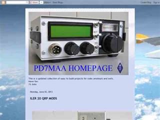
 I used a FT 240-43 for much more power, not needed but beter safe than sorry. 150 Watt continious, 300 Watt PEP SSB, 90 Watt Digimodes 10 Mhz, 18 Mhz, 24 Mhz Very easy to build design and a good antenna for people who don't have much space for big towers or long wires This design is from Hans - PE1RNU