Search results
Query: 500 meter band
Links: 18 | Categories: 0
-
 A 10-meter J-Pole antenna, detailed in QST February 1950, offers a straightforward solution for hams operating with restricted space. This design, originally presented by W1BLR, is a **half-wave radiator** fed by a quarter-wave matching stub, providing a low-angle radiation pattern beneficial for DX. The article describes building the antenna from readily available materials like copper pipe, emphasizing its simplicity and effectiveness for **single-band operation**. The J-Pole's inherent design provides a good impedance match to 50-ohm coaxial cable without the need for an external tuner, a significant advantage for portable or minimalist stations. Its nondirectional pattern ensures coverage in all directions, making it a versatile choice for general operating on the 28 MHz band. The construction plans are clear, allowing even those with basic workshop skills to assemble a functional antenna.
 -
 This PDF document, authored by KT4QW in October 2004, details the construction and modeling of a dual-band, horizontally polarized hanging rectangular loop antenna for **10 and 17 meters**. The design, adapted from *The ARRL Handbook*, utilizes _NEC4WIN95_ software for scaling and optimization, targeting a 50 ohm feedpoint impedance. The resource includes a bill of materials, step-by-step construction instructions, and a discussion of the antenna's radiation characteristics. It presents NEC-generated elevation and azimuth patterns, comparing the loop's performance to a half-wave horizontal dipole at the same height and frequency. The 17-meter element is centered at 18.140 MHz for low SWR across the phone band, while the 10-meter element is centered at 28.500 MHz. Construction involves 14-gauge stranded copper wire and Schedule 40 PVC spreaders, with the total wire length calculated by the formula: Length in feet = 1005/MHz. The feedpoint impedance can be adjusted by modifying the rectangular aspect ratio. The document specifies hoisting the antenna to at least a half-wave above ground for testing. It notes that a balun was tested and found to have no measurable effect on SWR or radiation characteristics. A 2-meter scale model is presented to illustrate the physical design, and a "rotator" string is incorporated for directional adjustment up to 90 degrees.
 -
-
 Presents a construction project for a linear-loaded 40-meter rotatable dipole, detailing the design evolution from mid-element coils to 300-ohm twinlead loading. It covers material selection, including repurposed fishing poles and EMT conduit, and outlines the assembly process for the antenna elements and mounting plate. The resource provides specific measurements for element lengths and linear loading sections, along with SWR plots demonstrating the antenna's resonance at 7.035 MHz with a 1.1:1 SWR, and bandwidth up to 7.120 MHz below 2:1 SWR. The article documents the antenna's performance during various RTTY and CW contests, including the SARTG RTTY and SCC RTTY contests in August 2006, and the ARRL DX CW and CQWW WPX RTTY contests in February 2007. It reports successful operation at 500-1000W, noting improved performance after replacing a faulty coax cable. Specific DX contacts from British Columbia, including stations in Europe and South Africa, are listed, illustrating the antenna's capability despite its shortened length and relatively low height of 55 feet. The content highlights practical considerations such as weatherproofing the connections and supporting the fiberglass elements to prevent sagging. It also includes a brief comparison to an inverted-V at similar height and a ground-mounted vertical, noting the rotatable dipole's quieter reception. The author shares insights into the iterative design process and tuning adjustments made to achieve optimal resonance.
 -
 A 500-watt mobile antenna project details the conversion of an old 10m hamstick into a highly efficient, multiband "bugstick" for HF operation. The core modification involves replacing the original coil with 25 turns of 6 turns-per-inch, 1.5-inch diameter coil stock, fabricated from #14 wire. This design, intended for a 3-magnet mount on a vehicle cab, achieves resonance on multiple bands by shorting out specific turns on the coil, similar to a **bugcatcher** antenna. Measurements taken with an MFJ-259 analyzer on a GMC pickup show 0 turns shorted for 20 meters (14.2 MHz), 10 turns for 17 meters, 16 turns for 15 meters, 19 turns for 12 meters, and 23 turns for 10 meters. The construction emphasizes using UV-resistant tie-wraps and #14 solid wire with crimp lugs for robust RF connections, bypassing the fiberglass rod for current flow. A bonus section details a 40-meter version, utilizing 48 turns of 8 TPI, 2-inch diameter coil stock.
 -
 Demonstrates the operational status and reception reports for the SK6RUD/SA6RR QRPP beacons, which transmit on 478.9 kHz, 1995 kHz, 10.131 MHz, and 40.673 MHz. These beacons utilize extremely low power, with the 630-meter beacon operating at approximately 0.1 watt ERP into an L-antenna, showcasing the potential for long-distance contacts under favorable propagation conditions. The site details the specific frequencies and antenna types employed, such as a vertical at 500 kHz and a 1/4 vertical for higher bands. The resource compiles over 10,530 reception reports from amateur radio operators worldwide, logging details such as date, time, band, RST signal report, locator, distance, and receiver setup. Notable long-distance reports include a 500 kHz reception by AA1A-Dave from 5832 km in 2008 and a 10.133 MHz reception by ZL2FT-Jason from 17680 km in 2010, illustrating the global reach of these low-power transmissions. Each log entry provides specific equipment used by the reporting station, including transceivers like the Yaesu FT817, ICOM IC-7300, and various antenna configurations such as coaxial mag loops, inverted Ls, and end-fed wires. The primary objective of the SK6RUD beacons is to challenge conventional notions of power requirements for effective two-way communication, proving that contacts over significant distances are achievable with minimal output. The site also includes a submission form for new reception reports, fostering community engagement and continuous data collection on propagation phenomena across different bands. The detailed logs offer practical insights into real-world propagation characteristics and the efficacy of QRPP operations.
 -
 During a club's "Filetto Day" event, a comparative field test was conducted between a **Buddipole** antenna and a homemade 20/40-meter wire dipole. The author, IW5EDI, performed this personal evaluation from a mountain top at 1500 meters above sea level, utilizing a Yaesu FT-857D transceiver to switch between antennas. The observations on the 20-meter band indicated that the wire dipole consistently delivered significantly stronger signals compared to the Buddipole. Additionally, the Buddipole exhibited higher levels of **QRM** during the listening tests. The commercial Buddipole, known for its multiband capability and compact size with a self-supporting tripod, was contrasted with the simpler, larger wire dipole, which required a fiberglass fish pole for support. This direct comparison highlights practical differences in performance and deployment between a popular portable commercial antenna and a basic wire antenna in a real-world operating environment.
 -
 This web article details the construction of a 4-meter band coaxial dipole antenna, designed for operation between **70.000 MHz and 70.500 MHz**. The resource provides a bill of materials and step-by-step assembly instructions for a half-wave dipole constructed from _RG-58_ coaxial cable. The design specifies a direct 50 ohm feedpoint impedance, eliminating the need for an external matching network. Construction photographs illustrate the stripping and soldering processes for the coaxial cable elements, ensuring proper electrical connection and physical integrity. The article includes specific dimensions for the radiating elements, derived from calculations for the 70 MHz band. The project outlines the physical dimensions required for resonance at 70 MHz, with the outer braid forming one half and the inner conductor forming the other. The feedline connection is directly to the coaxial dipole's center, maintaining a 50 ohm characteristic impedance. While the article does not present SWR plots or VNA sweeps, it focuses on the mechanical construction and dimensional accuracy for achieving a functional 4-meter dipole. The design is intended for fixed station use, with no specific mention of polarization or height above ground, but implies a standard horizontal orientation for dipole operation. DXZone Focus: Web Article | 4m Coaxial Dipole | Construction Guide | 50 ohm Feed
 -
 Makers of the The Polar Explorer transmitter, which operates on 9 HF bands from 160 through 10 meters and is capable of 500 watt peak output power on SSB, CW, AM, FM and RTTY. It is intended to be used in conjunction with a transceiver.
 -
 On March 27, 2017, the FCC adopted final rules for the USA 630-meter band, detailed in Report and Order FCC 17-33, which required PLC coordination with the Utilities Telecom Council before amateur operations could commence. This resource documents the WD2XSH experimental group's activities, including authorized stations, band plans, and frequency assignments within the 465-515 KHz range, with many stations operating between 495-499 KHz and 501-510 KHz. The site also highlights the WRC-12 decision on February 14, 2012, which granted a new **7-kilohertz-wide** secondary allocation between _472-479 kHz_ for the Amateur Radio Service worldwide. The group's efforts included operating with a maximum ERP of **20 Watts** across 45 stations in the continental USA, Alaska, and Hawaii, using emission modes such as CW, PSK-31, FSK-31, and MSK-31. The site provides links to download FCC 17-33 in PDF and DOCx formats, and offers a station location map, a list of stations by callsign and frequency, and an archive of news updates. Reception reports for any 600-meter station are encouraged to help the amateur radio community understand propagation and repeatability on this challenging band.
 -
 The Boone Area Radio Klub (BARK) serves Boone County, Iowa, as its local amateur radio club, actively welcoming visitors to its meetings and weekly ARES nets. The club maintains a 2-meter repeater on 146.850/250 MHz with a 114.8 Hz tone and a 440 MHz repeater on 443.9+ MHz, both situated at the Boone County Hospital, with a simplex fallback on 146.550 MHz for the 2-meter net. Additionally, BARK supports the Iowa 160-meter ARES net at 1.972.5 MHz, which operates at 9:30 PM on Sundays, featuring a rotating schedule of net controls including KNØR, KBØMPL, NØISU, KEØQEU, and KBØLPI. BARK conducts bimonthly license testing sessions on the second Saturday of even-numbered months, with specific dates like October 19, 2024, at the Hamboree, requiring a $15 fee and prior FCC Registration Number (FRN) acquisition. The club's activities are well-documented through numerous photo galleries from past Field Days (1998, 1999, 2008, 2010, 2013, 2017, 2018, 2019), JOTA events (2013), and special event stations (2010 B&SVRR&M). Members like KBØMPL (Margot Conard) have contributed educational PowerPoint presentations on topics such as "Fun with Handie Talkies," "HF Propagation," and "Digital Mode - FLDIGI - OLIVIA 8/500 - JT65 HF - BAND PLANS." The club's officers, as of May 2018, include WØFS (Clay Conard) as President, NØISU (Mitch Carroll) as Vice-President, and KBØLPI (Eric Sloan) as Treasurer/Secretary, guiding the club's operations and community engagement.
 -
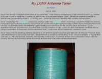
 This antenna is reported as being lower noise than conventional yagis and had a very low SWR for 500 KHz.
 -
 Building an End-Fed Half-Wave (EFHW) antenna from a kit, as detailed by Frank Bontenbal, PA2DKW, with process photos by Bob Inderbitzen, NQ1R, offers a practical approach for hams. This specific kit, a collaboration between ARRL and HF Kits, targets 10, 15, 20, and 40 meters, making it a versatile option for HF operations. Unlike a center-fed dipole, the EFHW is a half-wavelength antenna fed at one end, which simplifies deployment, particularly for portable use. The construction guide meticulously outlines the assembly of the 49:1 impedance matching network, crucial for transforming the antenna's high impedance (around 2,500 Ohms) to a transceiver-friendly 50 Ohms. Steps include preparing the enclosure by drilling holes for the coaxial connector and antenna connections, followed by the precise winding of enameled copper wire onto a toroid to create the transformer. The guide emphasizes careful insulation removal and soldering for reliable connections. Final assembly involves integrating a 100 pF capacitor for higher band compensation, soldering the transformer's primary and secondary sides, and conducting SWR tests with a 2K7 resistor or a half-wavelength wire. The document also provides examples of wire lengths for different bands, such as 16 feet for 10 meters or 66 feet for 40 meters, demonstrating the transformer's adaptability for various half-wavelength configurations.
 -
 Home made 40 meter transceiver project. The receiver is a Progressive Receiver with a few modifications. The Transmitter is a modified MFJ Cub circuit. Includes schematic and circuit diagrams for Receive Input Filter, 3-Pole 500 Hz Cohn Filter and 7 MHz Double Tuned Bandpass Filter
 -
 The article details the design and construction of a four-band Moxon beam by a radio amateur. The beam, mounted atop a rooftop tower, aimed for gain over a dipole on 20 meters, cost under $500, and included additional bands. The design features fiberglass spreaders, four bands (20/15/10/6 meters), and a single feedpoint. The construction involved computer modeling, NEC source code, and specific dimensions. The article outlines the assembly, materials, and tuning process, including in-situ adjustments for optimal performance. Despite initial challenges, the beam improved signal strength and facilitated contacts on multiple bands, marking it as the best HF antenna the author has owned.
 -
 KISS703 is a 703 Hz narrowband digital mode for amateur radio, designed for simple, low-power operation without computers. A 500 Hz pilot tone ensures frequency alignment, replaced by unique tones for 37 symbols (letters, numbers, space). Built from common discrete components, it draws about 40 mA at 12 V, ideal for SOTA/IOTA use. The receiver uses amplification, wave shaping, and a pulse-counting frequency meter for manual decoding via a calibrated meter. Transmitter and receiver calibration involves marking meter positions for each tone, enabling fully self-contained messaging with minimal hardware in portable or fixed operations.
 -
 The Olivia digital mode, a **Multi-Frequency Shift Keying (MFSK)** radioteletype protocol, is specifically engineered for robust communication under difficult propagation conditions on shortwave radio bands from 3 MHz to 30 MHz. Developed by Pawel Jalocha in 2003, Olivia signals can be decoded even when the noise amplitude exceeds the digital signal by over ten times, making it highly effective for transmitting ASCII characters across noisy channels with significant fading and propagation phasing. Early on-the-air tests by Fred OH/DK4ZC and Les VK2DSG on the Europe-Australia 20-meter path demonstrated intercontinental contacts with as little as one-watt RF power under favorable conditions. Common Olivia modes are designated as X/Y, where X represents the number of tones and Y is the bandwidth in Hertz, with examples including 8/250, 16/500, and 32/1000. The resource clarifies that Olivia, unlike some other digital modes, produces a constant envelope, allowing RF power amplifiers to achieve greater conversion efficiencies and making it less prone to non-linearity. Operators are advised that **Automatic Level Control (ALC)** can be set higher than no meter movement for MFSK modulation, as long as it's not driven past its high limit, contrary to common misinformation about other digital modes. The Olivia community encourages voluntary channelization on suggested calling frequencies, such as 14.0725 MHz for 8/250, to facilitate initial contacts, especially for signals below the noise floor. The Olivia Digital DXers Club provides links to Groups.io, Facebook, and Discord for community engagement and offers details on QSO parties.
 -
 Demonstrates the construction of an active loop converter specifically designed for the Low Frequency (LF) bands, addressing common localized noise interference in LF reception. The design integrates a sharply tuned circuit and a tuned loop antenna, utilizing the loop as the sole tuned inductive element. By applying positive feedback, the converter significantly increases the loop's effective Q, achieving factors between 1000 and 2000, which sharpens tuning and reduces noise. The circuit employs an _NE602_ mixer stage, feeding its output to an HF receiver, with a crystal-locked local oscillator at 4 MHz. A 20-turn, 0.8-meter square loop antenna with 500 uH inductance is detailed, connected via 2 meters of figure 8 flex cable. The converter offers three selectable frequency bands: 195-490 kHz, 150-220 kHz (including the New Zealand amateur band), and 128-160 kHz (covering the European amateur band). Performance measurements indicate an effective 3dB bandwidth of approximately 100 to 200 hertz at 200 kHz. The article provides insights into component selection, including an _LF353_ op-amp and a trifilar wound transformer on a ferrite core. Sensitivity figures are presented, showing 7.5 uV of converted output per 1 uV/meter signal strength into a 50-ohm load, or 37.5 uV into an _FRG7_ receiver, highlighting its capability to extract weak signals from noise.