Search results
Query: 50mhz
Links: 93 | Categories: 1
-
 The G5RV antenna, with an overall length of **31.10m (102ft)**, functions as a 3/2-wave on 20 meters when installed horizontally at 12m (39ft), exhibiting a resonant frequency of 14.150MHz and an approximate resistance of 80 ohms. Its 10.36m (34ft) stub line, designed as a 1/2-wave on 14.150MHz with a 0.97 velocity coefficient, acts as an impedance transformer across other bands, aiming for multiband operation without traps. On 20m and higher frequencies, the G5RV demonstrates improved gain compared to a standard dipole, attributed to the _collinear effect_ from multiple 1/2-waves along the wire. The original design sought a multiband solution for limited spaces, often requiring an Antenna Tuning Unit (ATU) for effective operation across bands like 80, 40, 30, and 20m, particularly with modern solid-state PAs. Variants, such as the F8CI modification, incorporate a 1/4 current balun at the stub line's base for symmetrical-to-asymmetrical transition, known as a _remote balun_. Proper flat-top or inverted-V installation is critical for maintaining symmetry and collinear gain, with inverted-V apex angles below 120° progressively diminishing higher-band performance.
 -
 Need a general purpose antenna on the magic band? The J-Pole is an easy-to-build and inexpensive device that provides an omni-directional vertically polarised antenna without the need for a ground plane. In technical terms, it is an end fed vertical 1/2 wave which is fed via a 1/4 wave matching stub.
 -
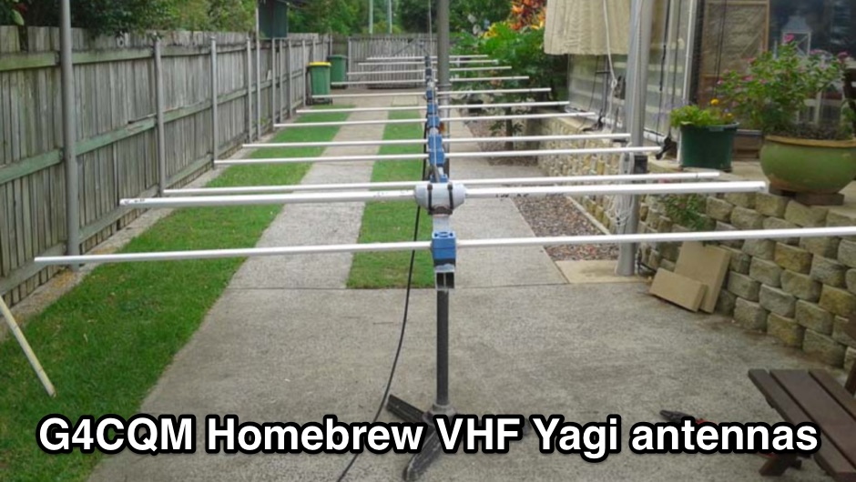 Homebrew VHF Yagi 50MHz 144MHz 432MHz 1296MHz 2320MHz 6M 2M 70CM 23CM 13CM Yagis
 -
-
-
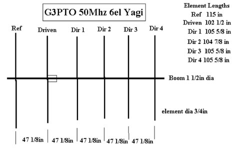 G3PTO antenna drawing plan for a 50MHz 6 Element Yagi beam
 -
-
 Build your own antenna for the 23cm band ( 1250Mhz - 1280Mc ) using some aluminium and this simple design.
 -
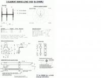 A 3 elements long yagi antenna for 6 meters band by ON6MU
 -
 Constructing a compact, directional antenna for the 6-meter band presents unique challenges, especially for operators with limited space or those seeking portable solutions. This project details the build of a 50 MHz Moxon rectangle, specifically engineered for balcony or temporary mast deployment, using readily available materials from a typical hardware store. The design emphasizes ease of construction and portability, allowing for quick setup and breakdown. The antenna's dimensions are precisely calculated using _Moxgen_ software for 50.200 MHz, ensuring optimal performance. Key construction techniques include using aluminum U-channel for elements, fiberglass driveway markers for insulation, and cable ties for secure assembly. The guide provides detailed instructions for fabricating the driven element, reflector, and boom, including a clever method for creating foldable element tips for transport. Performance observations indicate a respectable front-to-back ratio, capable of reducing an S7 signal to S0 when pointed away, and a modest gain over a simple wire antenna. The design incorporates a ferrite bead choke balun at the feedpoint to mitigate common-mode current and reduce shack noise, a critical consideration for urban or apartment-based operations.
 -
 This transverter was built in 1994, a discription in three parts (german language) for DOWNLOAD as PDF-files. Circuit, printed-boards and layouts in the files
 -
-
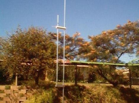
 50MHz-Yagis with a new match, all lengths from 0.6-12m
 -
 Comprehensive list of beacons in the 50MHz band maintained since 2013 by G3USF.
 -
 A 6 meters band amplifier width schematics
 -
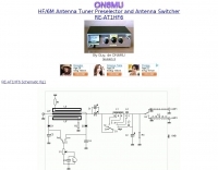 HF/6M antenna tuner preselector and antenna switcher project by ON6MU
 -
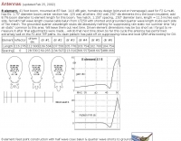 8 and 4 elemets yagi beam antenna by N6CA
 -
-
-
 JJ0DRC's HF multi-band delta loop antenna project, initially conceived during the waning peak of Cycle 23, addresses the common challenge of achieving effective DX operation from a small residential lot in Japan. Dissatisfied with a ground plane antenna's performance in SSB pile-ups, the author sought a beam-like solution without a tower, drawing inspiration from a JJ1VKL article in CQ Ham Radio Sep. 2000. The antenna, constructed in October 2000, employs two 7.2-meter fishing rods (37% carbon fiber, reinforced with cyano-acrylate glue and aluminum tape) and 1mm enameled wire, fed by an Icom AH-4 external antenna tuner. While the exact beam pattern remains unmeasured, JJ0DRC observed a significantly higher callback rate compared to dipole antennas, particularly on higher bands. The system's circumference length of 15-20m is crucial for maintaining a good beam pattern across HF bands, though performance on lower bands like 80m, 40m, and 30m becomes less directional as the length deviates from a full wavelength. Ongoing maintenance addressed degradation issues, including aluminum tape cracking and wire breakage at connection points due to strong winds (often exceeding 10-15m/s in winter). The author reinforced rod connections with IRECTOR PIPE SYSTEM components and INSU-ROCK ties, and improved wire attachment methods using Cremona rope and epoxy bond to enhance durability.
 -
 By 9H1EL, supports RSGB 21-28, BERU, IOTA contests, FOC marathon and IARU 50MHz trophy, Control of FT1000MP, all Kenwood and ICOM Radios which have CAT system.
 -
 Edited by Oz6OM to find out who's on 50MHz expeditions anywhere around the world. Most recent news on the web.
 -
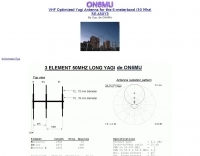 VHF Optimized Yagi Antenna for the 6-meter band (50 Mhz) by ON6MU
 -
 Supplier of amateur radio equipment for 50MHz and above in New Jersey
 -
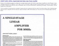 G3WZT design for a single stage bi-polar 100-150W Linear Power Amplifier for the 6M band.
 -
-
 Dutch Antenna and Tower Manufacturers from Slimline Square Triangular Round Towers. Antennas production include Yagi Monoband/Dipole/HF Quad /50MHz and 70MHz Yagi-Quad, VHF-UHF yagi-Quad and Comby antennas VHF/UHF/SHF
 -
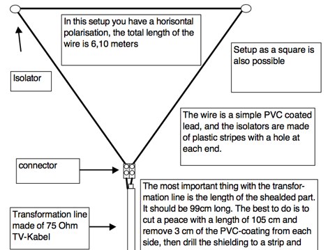
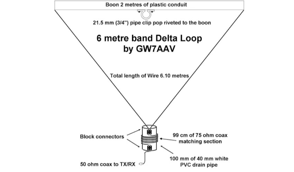 A simple delta loop antenna antenna for the six metre amateur radio band
 -
 Over two decades of historical DX spots and news are archived on this Japanese resource, providing a retrospective look at amateur radio propagation and activity across various bands. The content is organized chronologically, with separate sections for _50MHz_, _HF DX_, _144MHz_, _EME_, and Satellite clusters, detailing spot data from as early as 1996 through 2014. This extensive archive serves as a valuable historical record for analyzing long-term propagation trends and significant DXpeditions from a Japanese perspective, offering insights into band openings and rare entity activations. The resource also includes links to other DX news sites like _425 DX News_ and _Ohio/Penn DX Bulletin_, along with QSL manager lookups and callbook services, enhancing its utility as a comprehensive DX information hub. While the primary cluster data is historical, the compilation of external links points to active resources for current DX operations. This makes it a useful reference for contesters and DXers researching past conditions or seeking information on specific DX entities and their QSL routes.
 -
 Construction Details for 50MHz-Yagis in DK7ZB-Design
 -
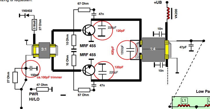 Converting a ZETAGI B303 power amplifier for 50 MHz usage
 -
 G3WZT design for a bi-polar 600W Linear Power Amplifier for the 6M band.
 -
 This document details the design and construction of a Vinecom 6N4 dual-band Yagi antenna for the 50MHz (6-meter) and 70MHz (4-meter) amateur radio bands. The antenna features 9 total elements (4 elements for 50MHz, 5 elements for 70MHz) on a 4.236-meter aluminum boom. Computer simulations using MMANA software predict 7.21 dBd gain on both bands with front-to-back ratios of 16.01dB (6m) and 15.37dB (4m). The design uses 12.7mm diameter elements mounted on a 32mm square boom, weighing 5.7kg total. Practical measurements with an MFJ-269 analyzer confirmed good SWR performance across both bands after element length adjustments.
 -
 6m (50Mhz) Long wire antenna There is another form of long wire antenna which provides uni-directional coverage and is easy to build. Description by Arnie Coro CO2KK
 -
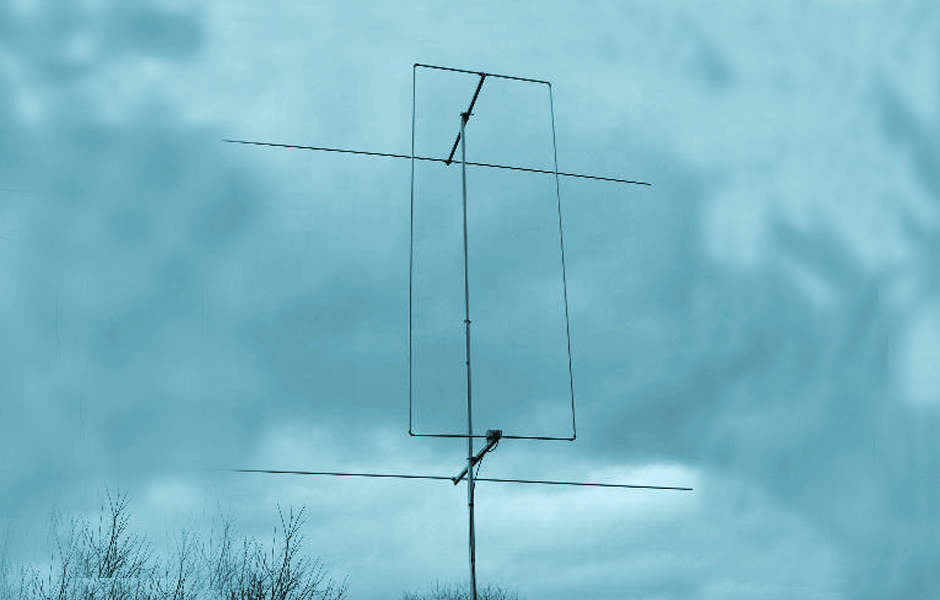 The Quadlong antenna for the six meter band. This antenna feature a total gain of 6,4 dBd, F/B 21 dB and is also available in 70MHz version. Includes detailed pictures and plot diagrams.
 -
 A SSB CW transceiver for six meters band with schematic and block diagram
 -
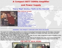 A Compact 8877 50MHz amplifier and Power supply
 -
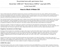 The webpage provides guidance on working 6 Meter DX, focusing on effective operating habits, preparation, and knowledge of the band. It emphasizes the importance of monitoring, clear frequencies, and using CW for weak signals. It also mentions the significance of knowing countries and individual stations on the air to increase chances of working DX. The page recommends utilizing resources like newsletters and websites to stay updated on 6-meter activity and offers suggestions for improving operating skills.
 -
 UKSMG news, message board, and articles dedicated to encouraging amateur radio on 50MHz around the world.
 -
-
 One of just a few webpages for the magic band, see it from the german point of view.
 -
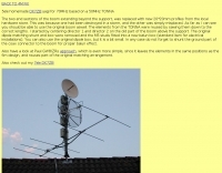 A 5 elements homemade DK7ZB yagi antenna for 4 meters band based on a 50MHz TONNA
 -
-
 Dedicated to 50MHz and 144MHz. Online 2m and 6m logs. Real Audio sound clips of Tropo, Aurora, Sporadic E, Meteor Scatter, TEP and F2 Propagation.
 -
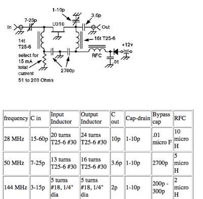 Extremely reliable FET preamplifier can handle several watts directly into either the input or the output without failure
 -
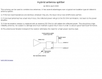 This scheme can be used to combine two antennas
 -
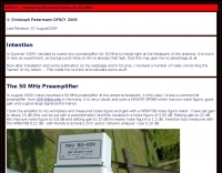 Tests on a preamplifier for 50 MHz installed right at the feedpoint of the antenna.
 -
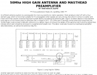 An high gain long yagi antenna, seven elements, for six meters band
 -
 Linear Amp UK specializes in the design and production of high-quality linear amplifiers, offering models for HF, VHF, and UHF amateur and commercial applications. The company emphasizes nearly 30 years of experience in crafting each unit, ensuring robust performance and longevity. Their product line includes amplifiers engineered for a 100% duty cycle, promoting continuous and reliable operation across various modes. The amplifiers feature solid, dependable designs, ensuring quiet and effortless performance during transmission. Each unit is hand-built to stringent standards, reflecting a commitment to durability and operational stability. All products are CE approved, confirming compliance with European safety and environmental directives, and come with a standard two-year warranty, providing assurance to operators. Key specifications often include coverage for 1.8-30MHz (WARC bands), 50MHz, 70MHz, and 144MHz, utilizing tubes such as 811, 572, 811A, 572B, GS35, GS35B, 8877, 3CX1500, and _3CX1500A7_ in their designs.
 -
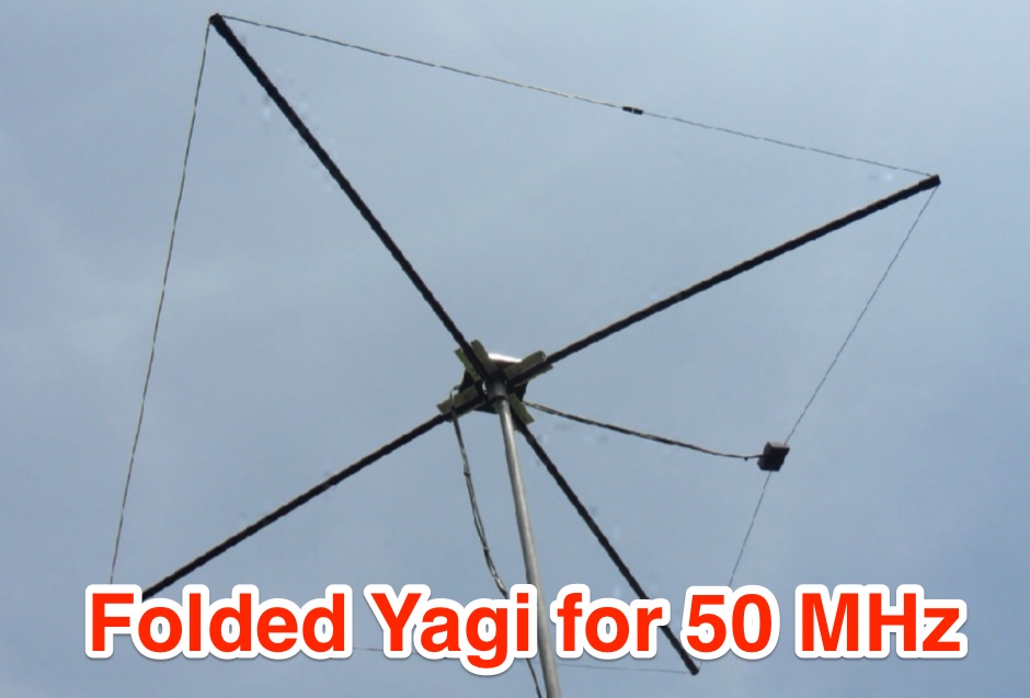 50MHz Collapsible 2 Element Mini Beam antenna, an overview the development of the 6MBA.